White Paper SSTI - VGB PowerTech
←
→
Page content transcription
If your browser does not render page correctly, please read the page content below

White Paper SSTI
Consideration of possible
impacts of the operation of
HVDC systems in the grid
on the shaft trains of
turbine-generator sets
in power plants
1st edition October 2020

         Prepared by power plant operators in
    VGB PowerTech and by the German transmission
       system operators, with the involvement of
             universities and manufacturers

                                         As of 1 August 2021
Contents

1       Introduction, objective .......................................................................................... 5
1.1     Scope ............................................................................................................... 5

2       Overview of grid restructuring/grid modification due to HVDC systems .......................... 6

3       Necessary exchange of information (relevant HVDC systems, relevant
        transmission system operator, relevant power plant connections) ................................... 7
3.1     Objective .......................................................................................................... 7
3.2     Information exchange for the grid connection process ................................................. 7
3.2.1         Information exchange in the context of necessary studies ....................................... 7
3.2.2         Information exchange in the context of the operational notification
              procedure .................................................................................................... 8
3.3     Information exchange during the entire operational lifetime .......................................... 8

4       Analyses necessary for the study of SSTI phenomena in connection with
        HVDC systems .................................................................................................... 9
4.1     National and European regulations......................................................................... 9
4.2     Analyses ............................................................................................................ 9
4.2.1         UIF screening ............................................................................................. 10
4.2.2         Detailed analyses ........................................................................................ 11
4.2.3         Demands on the models ............................................................................... 13
4.3     Summary ......................................................................................................... 15
4.4     Brief description of models .................................................................................. 16
4.4.1         Shaft train models........................................................................................ 16
4.4.2         Equivalent circuit diagrams of generators for the calculation of SSTI ....................... 18

5       Requirements for HVDC controls and HVDC protection systems................................... 20
5.1     Introduction ...................................................................................................... 20
5.2     Definition of the basis for the classification of HVDC systems ...................................... 21
5.2.1         Technical design ......................................................................................... 21
5.2.2         Control systems used in terms of their application and the control
              modes utilized ............................................................................................ 22
5.2.3         Specifications of the Europeans rules and regulations ......................................... 22
5.2.4         Standards applied to the operation of turbomachinery and generators ................... 23
5.2.5         Control and protection tasks in relation to the avoidance of torsional
              vibrations................................................................................................... 23
5.3     I&C design concepts for control............................................................................ 25
5.3.1         Concepts utilized for control .......................................................................... 25
5.3.2         Monitoring of control (e.g. self-monitoring for hardware faults) .............................. 25
5.3.3         Assumed faults and conditions and constraints for the design of
              a robust control ........................................................................................... 25

                                                                                                                             3
5.4     Measures intended to verify the robustness of the control ........................................... 25
5.4.1         Necessary input criteria ................................................................................ 25
5.4.2         General requirements for software testing (scenarios and assumed faults) ................ 26
5.4.3         Consideration of the interaction between different HVDC systems ......................... 26
5.4.4         General requirements for hardware tests .......................................................... 26
5.4.5         Feedback effect on power plant control ........................................................... 26
5.5     Classification and recommendations for damping sub-synchronous
        resonances....................................................................................................... 27
5.5.1         Classification of HVDC systems ...................................................................... 27
5.5.2         Definition of recommendations for assuring the robustness of
              the overall system ........................................................................................ 28

6       Literature .......................................................................................................... 29

7       List of abbreviations ........................................................................................... 31

8       List of figures..................................................................................................... 33

9       Annex ............................................................................................................. 34

10      Authors ............................................................................................................ 41

As of 1 August 2021: Update of the list „power plants, page 38, and
maps „HVDC connection nodes“, pages 39 and 40.

4
1     Introduction, objective
As the feed-in of renewable energy increases, the number of power electronic control elements in
Europe, and especially in Germany, also increases, and power generation by thermal power
plants decreases. Electricity transport by high-voltage direct current (HVDC) transmission is
becoming increasingly important with the growing use of both offshore and onshore wind turbines.
The grid topology also changes accordingly. In the following the aforesaid technical facilities are
subsumed under the heading “HVDC systems”, unless a deliberate distinction is required.
Existing generation systems, e.g. thermal power plants and their control systems, interact with the
controls of HVDC systems. Thermal power plants feature rotating (inertial) masses with the
appurtenant control systems. HVDC systems can implement control processes quickly. The
interaction of torsional vibrations of the shaft train of a power plant with other operating equipment
connected via the transmission network, such as HVDC systems, is termed sub-synchronous torsional
interaction (SSTI). If the design and parametrization of the engaged control systems do not take the
characteristics of the other components into account, impermissible loads on the shaft trains of
power plants can occur, among other things. Consequently, HVDC systems must be designed so
safely that no additional negative loads on a power plant shaft train can result due to torsional
vibration.
To enable integrating HVDC transmission technology safely and uniformly into the grid, in August
2018 VDE|FNN published the application rule “Technical Connection Rule for the connection of
HVDC systems and generation plants connected via HVDC systems”, in implementation of the
current European Network Code High Voltage Direct Current (NC HVDC).
This White Paper was jointly prepared by the German transmission system operators and power
plant operators with the involvement of universities and manufacturers. It provides an overview of
current grid modifications in the German transmission system. In addition, procedures and practices
for the integration of HVDC systems through information exchange and cooperation between
transmission system operators (TSOs), HVDC system operators and power plant operators are
presented. Analyses necessary to verify the design of HVDC system controllers are described and
explained. In conclusion, a brief overview of the demands on HVDC controls and protection
systems is provided.
This White Paper describes the fundamental relationships and provides joint recommendations for
steps to avoid impermissible SSTI stresses. It creates a basis on which the parties involved (HVDC
system operators, TSOs and power plant operators) should conclude project-specific agreements to
make future energy supply, including the changes in store for it, robust and safe, and to enable
proper feedback of experience from the operation of HVDC systems. Commercial expenditures
possibly arising from the application of the White Paper are not dealt with in the paper and, if
necessary, are to be agreed in the project between the involved parties.

1.1          Scope
Electrical disturbances caused, for example, by switching action, short circuits or disruptions in the
electrical system can induce torsional vibrations in the shaft trains of turbine-generator sets in power
plants.
The associated mechanical strain on the shaft depends both on the level, type and duration of the
excitation and on its decay behaviour, i.e., on the properties of the coupled electromechanical
vibration system.

                                                                                                       5
In the case of natural torsional frequencies of the turbine-generator set in the sub-synchronous
frequency range, interaction of the HVDC system with the power plant turbine-generator set via the
surrounding grid is possible under certain conditions:
In transmission systems with series compensation, the phenomenon of sub-synchronous
resonance (SSR) can occur if the armature voltage components induced by sub-synchronous
torsional vibration lie near a natural frequency of the series-compensated transmission
system.
Active network elements or control devices (e.g. voltage regulator and power system
stabilizer, turbine governor, HVDC control, etc.) can give rise to the phenomenon of SSTI,
in which case the active network elements influence the damping behaviour of the torsional
vibrations.
In the following the SSTI phenomenon is considered in connection with HVDC systems and the
analyses necessary to avoid negative SSTI phenomena are shown. However, it is pointed out that:
the SSTI phenomenon must not be considered as being exclusively connected with HVDC
systems, but generally can be caused by active network elements. Examples are shown,
inter alia, in [1].
active network elements can influence the damping behaviour of torsional vibrations both
positively and negatively, whereas solely negative interactions must be avoided.
2 Overview of grid restructuring/grid modification due to HVDC systems
The general overview (map and list) as of October 2020 of the installed and planned HVDC
systems and flexible AC transmission systems (FACTS), contained in Annex 1, gives an impression
of the expected local distribution of said systems and permits an initial assessment which power
plants might be affected by an interaction.
The precise marking of the effective radius of each HVDC system within which interaction can occur
between the power plants lying within the radius and the HVDC system was not possible during the
elaboration of this paper. A statement about this necessitates concrete analyses in project-specific
studies.
The 380 kV and 220 kV voltage levels are considered. Should anything be of relevance to the
power plants on the underlying voltage level 110 kV, it is included in the analyses.
For technical explanations the reader is referred to chapter 4, “Analyses necessary for the study of
SSTI phenomena in connection with HVDC systems”.
Notes:
Unlike the other HVDC systems considered, the grid connection of onshore wind farms is not subject
to VDE-AR-N 4131, but to VDE-AR-N 4130 for the connection of generating plants.
The FACTS are independently constructed and operated by the transmission system operators
based on valid VDE specifications and standards. Necessary studies are carried out, if need be, in
consultation between the relevant transmission system operator and the relevant power plants.
6
3 Necessary exchange of information (relevant HVDC systems, relevant transmission
system operator, relevant power plant connections)
3.1 Objective
This section of the report is concerned with the necessary exchange of information between HVDC
systems, power plants and, where applicable, other grid connections for the purpose of ensuring
safe and reliable grid operation in regard to SSTI.
3.2 Information exchange for the grid connection process
With VDE application rule VDE-AR-N 4131, requirements for HVDC systems contained in the
“Commission Regulation (EU) 2016/1447 of 26 August 2016 establishing a network code on
requirements for grid connection of high voltage direct current systems and direct current-connected
power park modules” (NC HVDC) were implemented nationally.
The NC HVDC lays down rules for, among other things, the provision of proof of the observance of
minimum general technical requirements and for the necessary exchange of information between
connectee and connection provider as well as the purposeful exchange of information on relevant
parties.
3.2.1 Information exchange in the context of necessary studies
The necessary exchange of information for grid studies pertaining to interactions is described in
detail in VDE-AR-N 4131 in Section 10.1.19.
The necessary exchange of information for grid studies on the damping of sub-synchronous
vibrations is described in detail in VDE-AR-N 4131 in Section 10.1.21.
In the framework of connection studies the relevant grid operator makes the following information
available to the power plants relevant to the HVDC connection being newly established (“Type 1
generating plants” according to VDE-AR-N 4131), and ensures the cooperation of the relevant
power plant operators:
Information to the relevant power plant about the UIF screening results with which the
detailed SSTI study will be conducted. This information should be provided to the affected
power plants at the earliest possible time so that the required activities of the power plant
operator can be included in the planning.
Active involvement of the relevant power plants (according to UIF screening) in regard to
duty points and power plant data for the detailed SSTI study.
Time for handover of the relevant duty points and power plant data by the power plant
operator for SSTI studies. It must be noted that procurement of the relevant data can take up
to 18 months.
Active involvement of the relevant power plants (according to UIF screening) in talks on the
essential results of the SSTI study.
Information exchange in regard to the grid studies (according to VDE-AR-N 4131 the
HVDC system must meet the requirements throughout the entire operating range):
o Operating range and scope of utilization cases
o Duty points of relevant power plants and HVDC systems
o The selection of relevant grid and power plant situations is largely the responsibility
of the expert who makes the study.
7
Time of and invitation to the presentation and handover of the results of the SSTI study. It
must be noted that measures of the power plant operator possibly will be derived,
implementation of which requires a certain amount of time prior to commissioning of the
HVDC system.
Interleaving with chapter Grid restructuring/grid modification due to HVDC systems (see chapter 2):
The relevant information about the locations of HVDC systems is available to the public through the
Grid Development Plan Power and the Offshore Grid Development Plan Power, as amended:
http://www.netzentwicklungsplan.de/en
This information was supplemented and suitably edited in this White Paper.
Interleaving with chapter Grid analyses (see chapter 4):
The information exchange necessary for the described grid analyses is already covered by the
specifications of VDE-AR-N 4131 Section 10.1.21.
3.2.2 Information exchange in the context of the operational notification procedure
The necessary exchange of information upon commissioning of HVDC systems is described in detail
in VDE-AR-N 4131 in Section 4.2.1.
The following times of the operational notification procedure are to be communicated about
3 months in advance:
Time of energization operational notification (EON) – energization of plant service
equipment
Time of interim operational notification (ION) – beginning of active use
The following times of the operational notification procedure are to be communicated in advance:
Probable time of final operational notification (FON) – beginning of intended operation
Duration of limited operational notification (LON) – deviations from intended operation
3.3 Information exchange during the entire operational lifetime
The necessary exchange of information upon repetition of parts of the demonstration of conformity
of HVDC systems is described in detail in VDE-AR-N 4131 in Section 11.4.
8
4 Analyses necessary for the study of SSTI phenomena in connection
with HVDC systems
The control system of an HVDC system is effective inter alia in the frequency range of the sub-
synchronous torsional vibrations and therefore can influence the damping of vibrations.
According to VDE-AR-N 4131 it is the task of grid operators and technical systems manufacturers to
ensure that the control system of the HVDC system does not exert any negative influence on the
damping of the sub-synchronous torsional vibrations. The power plant manufacturers and power
plant operators supply the necessary input data and contribute their experience to the investigations.
The close collaboration of all parties involved is designed to avoid negative impacts of the HVDC
system on the relevant power plants.
The explanations in this chapter 4 refer exclusively to the sub-synchronous frequency range.
Note:
Studies have shown that electrical disturbances in general – for example, caused by short circuits –
can induce torsional vibrations also in the super-synchronous frequency range and, in consequence
thereof, blade vibrations. Excitation by HVDC systems in this frequency range, on the basis of
current knowledge, is not known to occur. Should excitation by HVDC systems be demonstrated, for
example by simulations or measurements, the document will be expanded to reflect this.
4.1 National and European regulations
The type and scope of the analyses carried out in connection with SSTI are defined in:
Commission Regulation (EU) 2016/1447 of 26 August 2016 establishing a network code
on requirements for grid connection of high voltage direct current systems and direct current-
connected power park modules (NC HVDC) [2]
The Network Code in turn is the basis of the national regulations and application rule:
VDE-AR-N 4131, Technical Connection Rule for the connection of HVDC systems and
generation plants connected via HVDC systems [3]
The requirements laid down in these sets of rules are binding upon entry into force.
4.2 Analyses
Grid analyses for the avoidance of SSTI phenomena always are carried out in two steps:
1. Screening, i.e., identification of relevant power plant units that require detailed analysis
2. Detailed analysis of the relevant power plant units
9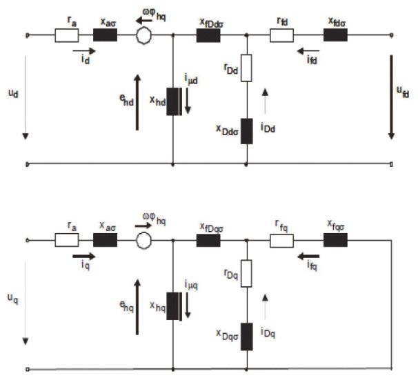
4.2.1 UIF screening
Of great importance for the assessment of the risk of SSTI is the relative size (rated capacity) of the
HVDC system at the point of connection as compared with the rated capacity of the power plant
unit under investigation:.
ெಹೇವ ௌಸೠ ଶ
ܷ ܨܫൌ ቀͳ െ ቁ
ெಸಶಿ ௌಸ
MVAHVDC : rated apparent power of HVDC system
MVAGEN : rated apparent power of the generator/power plant unit under study
SCGOUT : short circuit capability at the HVDC connection point without the generator under study
SCGIN: short circuit capability at the HVDC connection point with the generator under study
Major influence is exerted by the “electrical distance” between the HVDC system and the power
plant unit. These factors are assessed by taking the ratio of the short circuit capabilities at the grid
connection point of the HVDC system without and with the power plant unit concerned. From this
the so-called unit interaction factor (UIF) is determined.
With the aid of the UIF, the risk of the occurrence of SSTI can be assessed for power plant units as
a function of the grid state (topology, feed-in and load scenarios).
According to [4], for line-commutated HVDC transmission systems a UIF smaller than 0,1 is
considered non-critical. A power plant unit to which this applies therefore does not have to be
subjected to detailed analysis. The UIF analysis is performed taking into account various grid states
(make matrix of grid states).
For self-commutated HVDC systems there currently is no defined reference value. However, no
specific (control) properties of the HVDC system enter into the formula for calculation of the UIF,
shown above, so that initially the same reference value can be used for self-commutated HVDC
systems. Under a worst-case scenario a safety factor of 10 is added, i.e., a UIF smaller than 0,01
currently is assessed as non-critical and necessitates no further analysis in detail. As soon as new
findings are available in regard to these questions, the document will be modified accordingly.
Screening with UIF is state of the art and the basis for identification of the power plant units
requiring detailed analysis (see inter alia [1, 4]).
The screening should factor in the development of the grid short circuit capability in the next few
years, and the analysis should be performed in terms of a worst case estimate.
Should the grid short circuit capability at the HVDC connection point become weaker after an SSTI
study has been made, and this has not yet been recognized in the existing study, screening is to be
performed again and, where appropriate, necessary measures taken.
104.2.2 Detailed analyses
Various methods can be used for detailed analysis of the identified power plant units. The most
important are:
Small signal perturbation analysis in the time and/or frequency range
Large signal perturbation analysis in the time range (instantaneous value range) for defined
disturbance scenarios and excitations
Small signal perturbation analysis (frequency screening)
In the investigation of small signal perturbation, vibration is induced in the system starting from a
defined duty point. In the literature this method frequently is referred to as “small signal perturbation
analysis (SSPA)” or ΔMe/Δω analysis. Small signal perturbation can be analysed in both the
frequency range and the time range. Excitation is achieved by injecting monofrequent signals in the
speed governor (reference value application) of the power plant unit being analysed. Subsequently,
in the air gap moment the damping component that originates in the electric grid is evaluated. The
damping component of the electric moment is that part that is in phase with the speed deviation
(see Figure 1). For this the electric grid is modelled both with and without HVDC system (at the
same duty points and load flows). By comparing the results it is possible to assess the influence of
the HVDC system on the electric damping in the frequency range that is of interest. For ΔMe/Δω
analysis no detailed shaft train model is needed. The investigation traditionally is carried out using
a single-mass oscillator, while the inherent mechanical damping of the machine is neglected. Note:
The elimination of the sub-synchronous fractions from the polyfrequent signal in the low sub-
synchronous frequency range is suitable only as screening method.
For analyses in the frequency range, a linear model of the HVDC system validated by the technical
system manufacturer must be used in the relevant sub-synchronous frequency range. For small signal
excitation in the sub-synchronous frequency range, sufficiently high accuracy of the linear HVDC
model must be ensured. The influence of the HVDC system on the sub-synchronous vibrations also
can be analysed independently with the transfer function of the HVDC system. The evaluated real
component corresponds to the damping effect of the HVDC system on a vibration in the three-phase
system. This permits making a general statement as to which frequency range is critical or in which
frequency range there is still need for action.
Small signal perturbation analysis can be performed as pre-project study or in the engineering stage
of an HVDC system. It does not entirely substitute for analysis in the time range (large signal
behaviour). Small signal perturbation analysis also can be used as a frequency screening method.
11Transfer function of mechanical system (single-mass oscillator)
Transfer function of electrical system incl. HVDC
Speed deviation
Angular deviation
Change in mechanical torque
Change in electric moment
Fig. 1: Principle of ΔMe/Δω analysis. Vibration is induced in the turbine-generator set by injecting
a monofrequent extraneous signal in the speed governor. The component of the electric
moment in phase with the speed deviation is then evaluated [inter alia 4].
Analysis of large signal behaviour in the time range
For analysis of large signal behaviour, a detailed simulation model of the complete system (HVDC
system, power plant unit, relevant electric grid environment) is used and is analysed for defined
faults and excitations in the time range (instantaneous value range). For this analysis a mechanical
shaft train model is needed which reflects the dominant natural modes of the shaft train (see chapter
4.4.1).
The analysis in the time range makes allowance for defined system configurations (feed-in and load
scenarios, grid topology, short circuit capability, duty points of HVDC system, etc.). It has to be
shown that the parallel operation of generator and HVDC system, even under most unfavourable
conditions and constraints (minimal short circuit capability, radial connection of power plant and
HVDC system, most unfavourable duty points and operating states, etc.) is stable and non-critical in
regard to SSTI. As disturbance or excitation, among other things short circuits in the AC grid,
switching action in the AC grid, or changes in duty point of the HVDC system are assumed. By
performing the analysis both with and without HVDC system (at the same duty points and load
flows), it is possible to assess the influence of the HVDC system on the damping of the torsional
moments.
Assessment of the damping of the torsional moments calculated in the time range is made difficult
by the superposition of different modes. It therefore makes good sense to transform the torsional
moments between the individual masses of the shaft train into the modal range and to analyse the
modal torsional moments or rather the modal damping.
If a negative influence of the HVDC system on the damping of the natural torsional frequencies is
found, measures must be taken; for example, provision can be made for a damping control. The
aim is to design the HVDC system control in such a way that a positive contribution to damping
over the entire sub-synchronous frequency range is achieved from the outset.
Furthermore, provision can be made in principle for a control functionality that disconnects the
HVDC system or gradually reduces active power transmission when (poorly or negatively damped)
sub-synchronous vibrations are detected.
12This measure must be examined on a case by case basis:
It would be counterproductive if the HVDC system previously made a positive contribution to
damping and the inadequately damped sub-synchronous vibration were to have some other
cause. In this case, the damping would get worse.
There is a risk that the grid cannot manage the curtailment of one or more HVDC systems.
This is to be compared with the shutdown of a power plant unit.
Protective devices must operate selectively, safely and reliably and disconnect the protected asset
as quickly as possible if impermissible loads occur.
Since the asset being protected is the turbine-generator set, the power plant operator should
evaluate the use of appropriate protective devices for it. The results of the performed analyses
(power plant operator’s analyses and SSTI analyses) are included in this evaluation.
4.2.3 Demands on the models
4.2.3.1 Electric grid
For the analyses described in 4.2.2, a sufficiently large detailed section of the AC grid should be
considered. This section is determined by the screening study, which is performed on the original
model (referred to below as detailed grid model). This detailed grid model must be completed with
a suitable, reduced dynamic boundary grid model for representing electromagnetic transients
(EMT). The additionally considered boundary grid model simulates the interconnected system,
which is not modelled in detail, in such a way that the grid short circuit capabilities are properly
described in the detailed section. Furthermore, it must be ensured that the requirements of VDE-AR-N
4131 Section 10.1.19 can be observed with a view to the interaction between HVDC systems.
All relevant grid elements are modelled in the detailed grid model according to the frequency range
being considered, making allowance e.g. for possible saturation, resonance, etc.
4.2.3.2 Power plant models
Generators: Generators are modelled with their complete equivalent circuit diagram
according to Park (see chapter 4.4.2).
Shaft train models: The shaft train models must be able to simulate all relevant sub-
synchronous natural frequencies and pertinent natural modes with sufficiently great accuracy
(see chapter 4.4.1). Exact determination of the damping is possible only with great effort.
The conservatively estimated modal mechanical attenuation therefore is to be specified by
the power plant operator. The robustness of HVDC system behaviour is to be ensured for
the natural frequencies of the shaft train according to chapter 4.4.1. This way, differences
between theoretical model and the actual values of the natural frequencies and the
damping are taken into account.
Validation of the shaft train model through suitable measurements on the shaft train
concerned is recommended before carrying out the SSTI study.
13 Control models of power plants connected in the grid section being considered:
o If possible, for those power plants under study that are close to the HVDC
connection point, the exact turbine-generator set control models (voltage regulation
und turbine governing system) should be used. These depend on the manufacturer,
are confidential, and in practice also are not available for all power plants.
o An SSTI study can be carried out after verification with suitable recent IEEE models
of the power plants under study, e.g. ST6B models and the corresponding PSS
model (PSS – power system stabilizer). The applicability of the IEEE models to SSTI
studies should be confirmed by the manufacturer of the controller. If necessary, more
exact input filters for voltage measurement, speed measurement and active power
measurement are to be included in the control models. This must be clarified with
the manufacturer.
o Not all limiters in the controllers, e.g. overexcitation limiter, underexcitation limiter or
stator current limiter, play a role in SSTI studies. In very detailed studies the
intervention of a limiter in the voltage regulator during SSTI inducement also is
examined.
o In the case of turbine governors, the basic speed governor behaviour, including the
time constants of the turbines and turbine valves, is to be modelled. Load rejection
identification in the turbine governing system normally plays no role in SSTI studies.
Here again the manufacturer should supply the models and confirm the applicability
to SSTI studies.
o The control models must be capable of simulation in the instantaneous value range
(e.g. suitable simulation of actual value processing; note: Most models are
developed for classical stability in the RMS mode).
4.2.3.3 HVDC system models
A detailed EMT model including all relevant control functions is to be used. This includes, inter alia:
Higher-level control loops:
o active power control
o reactive power control and AC voltage regulation
o …
Subordinate control loops and near-converter control:
o AC current control
o possibly energy control or balancing control
o modulator
o …
Measurement acquisition and processing:
o phase-locked loops (PLL)
o filters
o …
Different control modes (e.g. for grid parallel operation and grid restoration) possibly have to be
considered.
14The control functions implemented in the HVDC system are strongly dependent on the specified
requirements and the specific way in which the manufacturer realizes them, so that no further
statements can be made here about the modelling of the HVDC system.
For the relevant control functions it is recommended that the appropriate control code implemented
in the control hardware also be included in the offline simulation studies (via dll interface). Note: For
this purpose ENTSO-E has developed a standard control interface for HVDC systems which, in
addition to faithful mapping of the control code used in the system, permits analysing relevant
signals within the HVDC control system down to the sub-module level, if necessary [18].
This makes it possible to ensure high reliability of the predictions of real-life system behaviour by the
simulation model.
Model verification should be carried out within the scope of the FPT/DPT (functional performance
test, dynamic performance test), and the SSTI analysis should be repeated for selected scenarios. In
the FPT/DPT the actual control panels are integrated in a real-time simulation environment by means
of HIL (hardware-in-the-loop).
4.2.3.4 Duty points, load cases and fault scenarios
Different duty points and scenarios have to be considered, among them:
Heavy loads/light loads in the grid
Topology changes at the point of connection, safety disconnection of electric circuits,
decoupling of coupled busbars, minimal short circuit capability, possible variation of the
short circuit levels
Overexcited/underexcited generator operation
Change in direction of HVDC power transmission
Fault cases in the grid (failure situations of grid systems such as electric circuits, possibly up
to the extreme case: HVDC remains connected to the power plant, but without grid
connection)
Power plant outages in the vicinity of the HVDC connection
HVDC controller modes in fault cases
Consider grid restoration studies separately if necessary
4.3 Summary
Under certain conditions and constraints, HVDC systems can interact with the turbine-generator sets
of power plant units in the surrounding grid, in which case the control equipment of the HVDC
system influences the damping of torsional vibrations. This phenomenon is termed “sub-synchronous
torsional interaction” (SSTI). However, the SSTI phenomenon also can be caused by other active
(controlling) elements (e.g. faulty power system stabilizer in the voltage regulator [1], faulty turbine
governor, or by converters for large motor drives in the power plant auxiliary service supply system).
This chapter 4 deals with grid analyses necessary for the purpose of avoiding negative SSTI
phenomena that can be initiated by HVDC systems. In a first step, power plant units are identified
which require detailed analysis. According to the state of the art, this screening is done today by
means of UIF analysis. In a second step, for identified power plants a detailed EMT analysis is
15performed utilizing the reduced1 torsional vibration model and a detailed HVDC model. In the SSTI
study proof is furnished that the HVDC system does not impair the damping of torsional vibrations in
the cases investigated.
4.4 Brief description of models
4.4.1 Shaft train models
A detailed calculation model of a shaft train under analysis usually consists of a great many
individual segments (as many as 300) featuring material-specific and temperature-dependent
stiffnesses, moments of inertia, and different modal damping parameters. These detailed models
permit an in-depth study of the sub-synchronous torsional vibrations in the shaft train, including even
an analysis of service life. In order to investigate sub-synchronous phenomena in the time range,
including electric grid and HVDC system, it is necessary to reduce the detailed shaft train model to
a few torsional masses. The reduced shaft train model usually is derived from the detailed shaft train
model.
The aim of preparing a reduced shaft train model is to keep the moments of inertia of the lumped-
together shaft train segments constant and to optimize the reduced models by adjusting the torsional
spring stiffnesses to the results of the detailed shaft train models, focussing on the easily excited
natural torsional modes in the area of the generator rotor body. Figure 2 shows the result of such
reduction [5].
Fig. 2: Comparison of a natural mode (detailed model, reduced model)
The curve of the calculated natural torsional modes shows which natural frequencies and associated
natural modes theoretically are at all capable of being excited by the electrical system (via the
generator).
Should it turn out upon reduction that the relevant natural modes and natural frequencies of the
detailed shaft train model cannot be modelled with sufficient accuracy, the torsional masses will
have to be further subdivided.
1
Shaft train model adapted to the highest relevant natural torsional frequency/natural torsional mode
16A shaft train model reduced to a few torsional masses usually is not suited for calculating fatigue
with acceptable accuracy. Should it turn out in a time range simulation, including relevant grid
segment and HVDC system, that the damping of single or all sub-synchronous eigenvalues is
reduced by the influence of the HVDC controls, the controls of the HVDC system will be adjusted to
rule out any negative influence on damping.
The exact effects on the shaft train can be considered by the power plant operator in a separate
calculation based on a detailed shaft train model.
The data of the reduced shaft train model shown below is required as minimum and is to be made
available by the power plant operator (different number of turbine masses possible depending on
power plant). The period of time necessary for procuring the data must be taken into account in
accordance with section 3.2.1:
Mass No. Description Inertia Part of starting torque
[kg m2] [%]*
M1 High-pressure turbine (HP)
M2 Intermediate-pressure turbine
(IP)
M3 Low pressure A turbine (LPA)
M4 Low pressure B turbine (LPB)
M5 Generator (GEN) -100
M6 Exciter (ERR) 0
Coupling Description Spring rate
from-to [Nm/rad]
M1-M2 HP-IP
M2-M3 IP-LPA
M3-M4 LPA-LPB
M4-M5 LPB-GEN
M5-M6 GEN-ERR
17Natural Calculated Modal damping
torsional frequency [expressed as logarithmic decrement]*
frequency No. [Hz]
1
2
3
4
5
…
* The modal damping values made available for all relevant natural torsional frequencies of a
shaft train are to be validated, if necessary, based on suitable measurements
Verification of the reduced shaft train model versus the detailed shaft train model:
Sub-synchronous eigenvalues and eigenvectors should be mapped with the greatest possible
accuracy compared with the detailed model. The maximum deviation of the natural frequencies in
individual instances must be no more than ± 0,5 Hz for the first 3 natural modes and no more than
±1 Hz for the higher modes. A comparison between reduced and detailed model is made
available.
The aforesaid deviations of the natural frequencies resulting from the reduction of the shaft train
model are to be taken into account in designing the control. In addition, it must be borne in mind
that deviations of the natural frequencies are unavoidable due to inaccuracies in the creation of the
detailed shaft train model. If the manufacturer is unable to state values for this additional deviation,
it is to be set at ± 0,5 Hz.
4.4.2 Equivalent circuit diagrams of generators for the calculation of SSTI
The best-known model for analytical description of the synchronous generator is the Park model [6]
or rather the extended model according to Park (field circuit and damper circuit in the d-axis, two
damper circuits in the q-axis), which describes the operating characteristics of the synchronous
generator in relation to the grid for steady-state and electromagnetic transient processes with
sufficient accuracy.
The parameters of the equivalent circuit diagrams according to Park are calculated in advance
analytically from the geometric dimensions and material data of the generator and verified with
sudden short-circuit tests. This modelling focuses on events with simple and double system
frequency, which account for most transient processes.
However, the model also is valid for frequencies which deviate from 50 Hz and 100 Hz and is
thus suitable for SSTI studies [7].
18Canay shows in [8] that the assumption of equal magnetic coupling between the stator winding
and the damping and field windings leads to a partly inaccurate calculation of the rotor currents in
regard to the distribution of the AC components between damper winding and field winding in the
case of transient processes. Canay enlarged the original model by inserting additional “Canay
inductances” between the stator circuit and rotor circuit (see Figure 3).
Allowance for the Canay reactance is state of the art. If the appropriate equivalent circuit diagram
can be made available by the manufacturer of the generator, it should be used. If the Canay
reactance is not available, the extended Park model can be used for SSTI studies. The Canay
reactance generally has a negligible effect on the terminal behaviour of the generator.
Fig. 3: Equivalent circuit diagrams of a synchronous generator with two damper circuits, extended
according to Canay: a) d‐axis, b) q‐axis (Source: NETOMAC‐Theoriebuch)
195 Requirements for HVDC controls and HVDC protection systems
5.1 Introduction
Torsional vibrations in turbine-generator sets of power plants can be initiated or induced by different
scenarios and are known from the literature [4, 9, 10]:
Possible influences of the power plant on torsional vibrations of the turbine-generator set:
Out-of-phase synchronization of power plant generators
Load rejection to auxiliary station supply
Interaction with drive converters in the power plant auxiliary system
Rectifier with static excitation
Fault in the voltage regulator or power system stabilizer
Fault in asynchronous machine in the plant auxiliary system
Possible influences of the transmission system on torsional vibrations of turbine-generator sets:
Faults or short circuits in the system
Switching action in the system (planned or unplanned)
Interaction with series compensation of long lines
Asymmetrical phases in the system
Interaction with HVDC systems
Effects of lightning strikes in the system
Increased rates of change of frequency (RoCoF)
Basically, resonance excitation in turbine-generator sets can be calculated and also measured using
models [7, 11].
The following considerations deal exclusively with possible interactions between HVDC systems and
turbine-generator sets in power plants.
HVDC systems use converters to couple three-phase and direct current systems. Taking into account
their technical design, the converters can be operated in both directions as rectifier or inverter. As
the three-phase current is generated by means of power electronic components (e.g. thyristors or
IGBTs), converters can be regulated more flexibly and more quickly compared with synchronous
generators.
The control systems used in the converters have the purpose of ensuring the load flow between
three-phase system and direct current system in accordance with the requirements of the transmission
systems. If the controls are not properly designed or incorrectly parameterized, or if there are faults
in the controls, the actuator or the power electronics, due to the negative damping that results from
this the converter can produce interactions with the three-phase system and the turbine-generator set
which lie outside the system frequency range (47 Hz to 52 Hz). In generation systems with
synchronous generators within the range of influence of such a faulty converter, these interactions
can lead to increased fatigue or damage on components of the turbine-generator set [4, 7, 9, 10].
20The following considerations should provide insights into the different technical versions of the
HVDC systems and the converters used, as well as enable a risk assessment by HVDC operators,
transmission system operators and power plant operators in regard to the described interactions.
5.2 Definition of the basis for the classification of HVDC systems
Various HVDC converter principles are known from the literature [12].
Currently, the following HVDC systems are in use or planned in Germany for the following
purposes:
HVDC systems for connections between different asynchronous transmission systems
(interconnector)
HVDC systems for connecting offshore wind farms to the three-phase network
(offshore wind farm)
HVDC systems connected to a direct current transmission line or to a direct current network
within a transmission system (overlay link)
Multi-terminal combinations of different connections to an HVDC system
(interconnector & offshore wind farm; interconnector & overlay link)
In chapter 2 (see also 7 Annex) a survey of existing and planned HVDC systems is provided.
5.2.1 Technical design
The following converter technologies can be distinguished:
Converters with LCC (line-commutated converter) technology
The converters with LCC technology usually consist of 12-pulse thyristor-controlled bridge circuits
which are connected in specific sequences (phase angle control) in order to perform either the
rectifier or inverter function. These converters are line-commutated and hence depend on an existent
voltage of the three-phase system. This technology using thyristors was introduced around 45 years
ago and therefore has proven reliable for decades.
Converters with VSC (voltage source converter) technology
The converters with VSC technology make use of turn-off power semiconductors such as IGBTs.
These self-commutating converters feature load-independent direct current and, with suitable control,
can modulate AC voltage. They thus have black-start capability and offer, among other things,
higher switching frequencies, considerably reducing the need for passive filters compared with the
LCC technology. The VSC technology was introduced in 1997 (in use in Germany since 2010) so
that long-term operating experience is not available. Current VSC converters for large HVDC
systems have a modular design with MMC (modular multilevel converter) technology [13] (in use in
Germany since 2015).
215.2.2 Control systems used in terms of their application and the control modes utilized
Depending on the utilized technology, the possibilities for control differ; consequently, the potential
technical solutions for avoiding unwanted interactions due to frequencies outside the system
frequency range differ as well.
According to VDE-AR-N 4131, when conducting the SSTI study the complete controls including all
envisaged control modes of the HVDC system always must be taken into account.
The influence of individual control modes on the reaction of the HVDC system in the relevant sub-
synchronous frequency range is to be demonstrated. All control modes that (can) influence plant
behaviour in regard to sub-synchronous interaction have to be included in the detailed study.
The following characteristics can be assigned to the individual technologies [12, 14]:
Converter station in LCC technology:
Acquisition of the reference signal by means of phase-locked loops (PLL)
Direct current in the intermediate circuit
Current-driven control
For active power reversal the output voltage on the direct current side is used (direction of
current flow remains the same)
Firing angle control, commutation through selective energization of the thyristors, and
control through symmetric timing of the thyristors (EPC – equidistant pulse control)
Converter station in VSC technology:
Acquisition of the reference signal by means of phase-locked loops (PLL)
DC voltage in the intermediate circuit
Voltage-oriented current control
Active power control and reactive power control possible
Rapid power flow reversal possible through reversal of current flow
Generation of AC voltage through controlled switching on and off of the valves
Switching frequencies of up to 2 kHz possible
Black-start capability possible
5.2.3 Specifications of the Europeans rules and regulations
The applicable requirements were already stated in chapter 4.1.
225.2.4 Standards applied to the operation of turbomachinery and generators
High demands are made on the operation of turbomachinery and generators in power plants and
industrial installations. In this connection, the following documents were and are drawn up by
VDMA (German Mechanical Engineering Industry Association) taking into account the Machinery
Directive, harmonized standards IEC 62061, ISO 13849, and standards of the process industry
IEC 61508 and IEC 61511:
VDMA 4315 Turbomachinery and generators – Application of the principles of functional safety –
Part 1: 4315-1 Methods for determination of the necessary risk reduction
Part 2: 4315-2 Existing plants
Part 5: 4315-5 Risk assessment steam turbines
Part 8: 4315-8 Risk assessment hydrogen cooled generators
Part 9: 4315-9 Risk assessment air cooled generators
Summarising, SIL (safety integrity level) studies always are carried out to evaluate the risk, and
suitably qualified technology is used for the protective devices.
5.2.5 Control and protection tasks in relation to the avoidance of torsional vibrations
The HVDC converters on the transmission system side have the purpose of regulating the electric
power and frequency in accordance with the constraints and requirements of the transmission
system. The controls of LCC and VSC converter stations are continuously in operation.
Control of converters that use LCC technology
With LCC technology, interactions can lead to stronger torsional interaction in the event that faultily
generated power oscillations in the sub-synchronous frequency range affect the natural torsional
frequencies of a turbine-generator set within the area influenced by an HVDC system, and no
damping control is implemented [4, 9, 10, 14, 15, 16].
A change in magnet wheel angle leads to corresponding voltage changes via the grid infeed. The
controls of the line-commutated (LCC) converter seek to compensate the change.
The following parameters can amplify or influence sub-synchronous interaction:
operating mode or control mode, in particular current regulation
rated point of the HVDC system
higher firing angle
firing angle control
voltage stiffness at the grid connection point of the converter
Protection from torsional vibrations if LCC technology is used
For LCC converter stations, in the event of a problem with torsional vibrations an additional
damping controller is designed. This damping controller has the purpose to generate a positive
damping behaviour of the converter [13, 15].
23Furthermore, the HVDC system can be provided with a device that is able to detect a beginning
torsional vibration based on the measured direct current. If a beginning torsional vibration, or one
that does not attenuate quickly enough, is detected, if necessary the power can be reduced or the
HVDC converter station can be switched off.
Control of converters that use VSC technology
The control of converters that utilize VSC technology is more complex than the control of LCC
technology [15, 17]. Suitable control concepts and measures also are available in VSC technology
and, if need be, are implemented to manufacturer specification so that the HVDC system is able to
contribute to the electrical damping of torsional vibrations and meet the requirements of Section
10.1.21 VDE AR N 4131.
The following parameters can amplify or influence sub-synchronous interaction:
Operating mode dependent on selected control concept (individual approach required
depending on manufacturer and system configuration).
Concept and design of the control, plus the parameterization, have major influence on the
stability and properties of the damping.
The objective is therefore concepts in which the damping is inherently included in the normal
control. This control behaviour can be achieved through the design of the control and the project-
specific parameterization.
The control is then designed so that the real part of the transfer function in the relevant frequency
range is always positive. In this case the converter makes a contribution to the damping of torsional
vibration.
In normal and thus pre-specified operation, this characteristic always will result in improvement of
the original damping. The property that the real part of the transfer function in the relevant frequency
range and in all operating modes of the converter (rectifier, inverter) is greater than zero is achieved
in a project-specific way.
In the VSC technology the HVDC system can be provided, for example, with a device that is able
to detect a beginning torsional vibration. However, for detection the VSC technology does not
make use of the direct current, but instead the busbar voltage at the connection point of the
converter.
Torsional vibration monitoring systems independent of the controls
A fundamental requirement for the safe and reliable operation of HVDC systems without negative
repercussions on power plants is the correct design of the hardware and software of the control
systems and their fault-free operation.
A monitoring system completely independent of the HVDC control, where torsional vibrations are
concerned, generally is not envisaged at the current time.
245.3 I&C design concepts for control
5.3.1 Concepts utilized for control
The control system of HVDC systems is designed redundantly with 2 channels. Interruption-free,
smooth switchover in the event of faulty regulation in one channel is possible. The cycle time is
approximately 50 μs. Signal evaluation for channel switching is performed according to the
specifications of the HVDC system operator.
The control system design is manufacturer-specific and software-based.
5.3.2 Monitoring of control (e.g. self-monitoring for hardware faults)
Self-monitoring of the control takes place on a continuous basis. Among other things, it covers the
case of an interruption of the electric supply of a control channel. According to the specifications
the HVDC system can continue operating without restrictions even if single IGBT modules (VSC) fail.
Currently there are no provisions for specific monitoring of turbine-generator sets for natural
frequencies and resonance frequencies within the area of interaction.
5.3.3 Assumed faults and conditions and constraints for the design of a robust control
The faults assumed for the design of the control are to be agreed with the respective HVDC system
contractor. The usual network failures always are considered. The study investigating sub-
synchronous interaction is carried out for different rated points of the output diagram of the power
plant generators in the area of interaction. In addition, the mechanical damping of the turbine-
generator set in the simulation is conservatively set at D=0 or to very low values (no damping
effect). The minimum short circuit capacity specified by the network operator has a major influence
on the setting of the controller.
5.4 Measures intended to verify the robustness of the control
5.4.1 Necessary input criteria
The power plant’s input data are needed to permit making a proper study and analysis of sub-
synchronous resonances on turbine-generator sets. Along with the electrical data of the connection
(generator output diagram, generator step-up transformer…) the models, data and settings of the
voltage regulator and, if available, of the power system stabilizer (PSS) are required. In selecting
the duty points, the real conditions and constraints of power plant operation are to be taken into
account, e.g. auxiliary station supply losses, own consumption of reactive power.
The mechanical parameters and a simplified shaft train model of the turbine-generator set also are
needed for the SSTI study.
25You can also read