EPA Section 608 Preparatory Manual - 9th Edition
←
→
Page content transcription
If your browser does not render page correctly, please read the page content below
EPA Section 608
Preparatory Manual
      9th Edition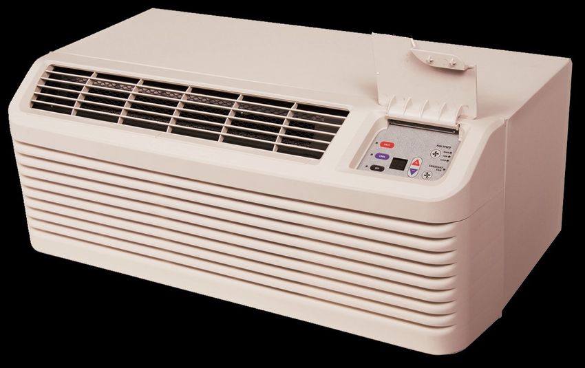
EPA Section 608 Preparatory Manual

This manual was developed by The ESCO INSTITUTE
Mount Prospect, IL 60056

                                              ESCO Institute
                                               P.O. Box 521
                                          Mount Prospect, IL 60056

                        Phone: (800) 726-9696                 Fax: (800) 546-3726
                Website: www.escogroup.org           E-Mail: customerservice@escogroup.org

COPYRIGHT © 2018 ESCO INSTITUTE
All rights reserved

Printed in the United States of America
ISBN 1-930044-60-7

No part of this manual may be reproduced, stored in a retrieval system, or transmitted by any means,
electronic, mechanical, photocopying, recording, or otherwise, without written permission of the authors. No
patent liability is assumed with respect to the use of the information contained herein. While every precaution
has been taken in the preparation of this book, the authors and publisher assume no responsibility for errors
or omissions. Neither is any liability assumed for damages resulting from the use of the information contained
herein.

           Disclaimer: Passing the EPA Section 608 Certification Exam is required for handling
           and purchasing regulated Refrigerants.

           The 608 certification is not an indicator of an individual’s competency as an installer
           or service technician and does not replace formal training one should receive prior to
           taking this examination.

   2                                                                              ©ESCO Institute 2018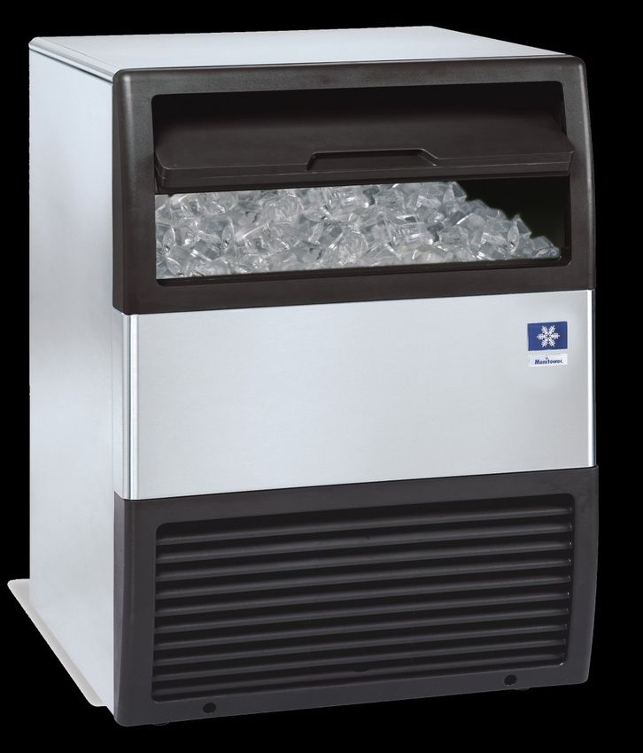
EPA Section 608 Preparatory Manual

Introduction
Overview of the Examination         4

                                                                 Table of Contents
Core
Stratospheric Ozone Depletion        8
Ozone Depletion Potential            8
What is global warming?              8
Clean Air Act                        9
Montreal Protocol                   10
The Three 'R's                      10
Recovery Devices                    11
Sales Restriction                   11
Substitute Refrigerants & Oils      11
Recovery Techniques                 12
Leak Detection                      13
Dehydration                         13
Recovery Cylinders                  14
Safety                              15
Shipping & Transporting             15
Refrigerant Characteristics Table   16

Type I Certification
Equipment Requirements              17
Leak Repair Requirements            17
Recovery Techniques                 17
Safety & Shipping                   18

Type II Certification
Leak Detection                      19
Leak Repair Requirements            19
Recovery Techniques                 20
Recovery Requirements               20
Refrigeration Notes                 21
Safety                              22

Type III Certification
Leak Detection                      23
Leak Repair Requirements            23
Recovery Techniques                 24
Recharging Techniques               24
Recovery Requirements               25
Refrigeration Notes                 25
Safety                              25

Saturation Chart                    Back Cover

   ©ESCO Institute 2018                                                     3
EPA Section 608 Preparatory Manual

               This manual is intended to prepare technicians for the Environmental Protection Agency’s (EPA)
Introduction
               Section 608 Certification examination and contains the information required to successfully
               complete the exam. This book serves as a guide for reviewing material related to the amendment
               of Section 608 of the Clean Air Act and is not a formal refrigeration training course. Technicians
               preparing for this examination should be familiar with the basic vapor-compression refrigeration
               cycle, as well as common service principles, practices and procedures.

               This manual has been developed with the most current information available at the time of
               publication. Should EPA regulations change after a technician becomes certified, it is the
               responsibility of the technician to comply with these changes. The EPA also reserves the right
               to modify the test questions and/or require new certification or recertification based on
               advancements in technology. The ESCO Institute will update this manual as necessary to
               reflect current EPA regulations and testing requirements.

               Federal Regulations
               Section 608 of the Clean Air Act requires that all persons who maintain, service, repair, or
               dispose of appliances that contain regulated refrigerants, be certified in proper refrigerant
               handling techniques as required by the EPA’s National Recycling and Emission Reduction
               Program. Regulated refrigerants currently includes: CFC, HCFC, HFC, and HFO refrigerants.

                      You cannot work under another person’s certification.

               Before You Begin
               In addition to this preparatory manual, practice questions are available to help prepare you for
               the EPA Section 608 examination. You can access these practice questions free of charge on
               the ESCO website at www.escogroup.org.

               If your examination was administered through an ESCO approved testing location, you will be
               able to login to the ESCO website to access your examination results, order replacement
               certification cards, update your information (i.e., address), opt out of the public certification
               registry, order additional training materials, etc. You may also contact our customer service
               team, Monday-Friday, 8:00 AM 5:00 PM Central Time at 1-800-726-9696 if you have any
               questions related to your certification. Please note: if you participate in an examination that
               was administered in paper format (i.e., Scantron answer sheet), please allow 5-7 business
               days for your examination to be received at our grading center for processing.

               Overview of the Examination
               Distributors can only sell regulated refrigerants to a Section 608 certified technician or company
               which employs a Section 608 certified technician.
               There are four (4) categories of technician certification:
               Type I. Persons who maintain, service, repair, or dispose of small appliances must be certified
               as Type I technicians. A small appliance is defined as a pre-assembled unit, hermetically
               sealed and factory charged with 5 lbs. or less of refrigerant. Examples include equipment such
               as water coolers, window units, refrigerators, freezers, de-humidifiers, ice machines, and
               package terminal air conditioning. Split systems are not included in Type I.

               Type II. Persons who maintain, service, repair, or dispose of medium, high and very high
               pressure appliances containing more than 5 lbs. of refrigerant or if the installation of such
               equipment requires refrigerant charging, must be certified as Type II technicians.

     4                                                                              ©ESCO Institute 2018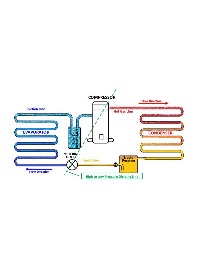
EPA Section 608 Preparatory Manual

High-pressure refrigerants have a pressure between 155 psig & 340 psig at a liquid phase

                                                                                                      Introduction
temperature of 104°F and medium pressure refrigerants have a pressure between 30 psig &
155 psig at a liquid phase temperature of 104°F. Type II certification does not include small
appliances or motor vehicle air conditioning (MVAC) systems.

Type III. Persons who maintain, service, repair, or dispose of low-pressure appliances
(centrifugals and chillers) must be certified as Type III technicians. Low-pressure refrigerants
have pressures of 30 psig or lower at a liquid phase temperature of 104°F.

Universal To be certified as Universal, a technician must pass all four sections; Core, Type I,
Type II, and Type III.

Test Format
The test contains four sections: the Core, and sections I, II, and III. Each section contains
twenty five (25) multiple-choice questions. A technician MUST achieve a minimum passing
score of 70 percent in each group/section in which they are to be certified. For example, a
technician seeking Universal certification must achieve a minimum score of 70 percent, or 18
out of 25 correct, on each section of the test. If a technician fails one or more of the sections,
they may retake the failed section(s) without retaking the section(s) in which they earned a
passing score. In the meantime, the technician will be certified in the Type for which they
received a passing score. There is one exception; a technician MUST achieve a passing score
on the Core plus any one Type to receive any certification.

The Core contains 25 general knowledge questions relating to stratospheric ozone depletion,
rules and regulations of the Clean Air Act, the Montreal Protocol, refrigerant recovery,
recycling and reclaiming, recovery devices, substitute refrigerants and oils, recovery
techniques, dehydration, recovery cylinders, safety, and shipping. Section I contains 25 sector
specific questions pertaining to small appliances. Section II contains 25 sector specific
questions pertaining to medium and high-pressure appliances and Section III contains 25
sector specific questions pertaining to low-pressure appliances.

Federal regulation requires that this exam be conducted as a closed book exam by an authorized
test administrator (Proctor). The only outside materials allowed during the test are a temperature/
pressure chart and a calculator. Phones are NOT allowed to be used during the examination and
MUST be turned off and put away (not on the desktop) during the examination.

•   Picture Identification (Proctors will ask for this to verify your identity–this is required.)
•   Social security number (Used for identification purposes only.)
•   Home/mailing address
•   Date of Birth
•   Phone Number
•   Email address

All examination participants will be included in an online registry/lookup by name, city and
state as well as certification achieved. (No personal information will be included in the public
registry.) Technicians will be able to opt out of this registry by logging into the ESCO website
at www.escogroup.org or by contacting customer service at 800-726-9696.

Technicians should carefully study the Core and section(s) related to the Type(s) of
certification in which they are seeking to achieve a passing score. Free EPA practice exams
can be found online at: www.escogroup.org.

    ©ESCO Institute 2018                                                                                     5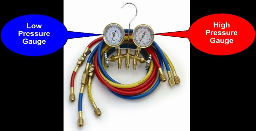
EPA Section 608 Preparatory Manual
Introduction

                                     Figure 1. Basic Vapor/Compression Refrigeration Cycle

               Vapor / Compression Refrigeration Cycle
               The compressor is the heart of the vapor-compression refrigeration cycle. Low-pressure, low-
               temperature superheated refrigerant vapor entering the compressor is compressed, changing
               it to a high-pressure, high-temperature, superheated vapor. It then moves to the condenser
               where the heat is removed, de-superheating and condensing it into a liquid. Before it leaves
               the condenser, the liquid refrigerant is subcooled to a point below the liquid saturation
               temperature. It then flows to the metering device as a high-pressure, subcooled liquid. As the
               refrigerant flows through the metering device, the liquid is reduced to a low-pressure causing a
               small percentage of the liquid to flash to a vapor (flash-gas) lowering the remaining refrigerant
               to its saturation temperature. The low-pressure, low-temperature refrigerant flows into the
               evaporator as a low-temperate liquid. As the refrigerant absorbs heat, it evaporates into a low-
               temperature vapor. During this process the refrigerant vapor is superheated above its
               saturation temperature and then enters the suction line. From the suction line, refrigerant
               enters the compressor as a low-pressure, low-temperature superheated vapor to repeat the
               cycle. The compressor and the metering device are the dividing points between the low-
               pressure and high-pressure sides of the system.

               Accessories shown in the basic diagram are the liquid receiver and a suction accumulator.
               Use of these components depends on system design and/or the type of metering device used.
               A system that uses a thermostatic expansion valve (TEV) is usually equipped with a receiver
               located in the liquid line directly following the condenser. A system that uses a thermostatic
               expansion valve (TEV), capillary tube, or fixed bore metering device may be equipped with an
               accumulator located in the suction line, which prevents liquid from entering the compressor.

               A system may have service valves, access valves or process stubs to gain access for service.
               Never front-seat (turn the valve stem clockwise as far as it will go) a service valve when the system
               is in operation. The valve must be back-seated (turn the valve stem counter-clockwise as far as
               possible) to close the service or gauge port before removing the service manifold hoses.

     6                                                                                ©ESCO Institute 2018
EPA Section 608 Preparatory Manual

                                                                                                 Introduction
       Figure 2. Manifold and Hose Set          Figure 3. Digital Manifold and Temperature Kit

Gauge Manifold Set
One of the most important tools for an HVACR technician is the gauge manifold set. The left
side, compound gauge (blue) and the right side, high-pressure gauge (red), are attached to
the manifold to measure system pressures. Hoses are used to connect the manifold to the
refrigeration system’s access ports or service valves to gain access to system pressures.
The compound gauge measures low-pressure (psig) and vacuum (inches Hg). The high
pressure gauge measures high side (discharge) pressure. Depending on the refrigerant, the
high-pressure gauge may be rated at 500 or 800 psig. The manifold is also equipped with a
center port, (usually a yellow hose), that can be connected to a recovery device, evacuation
vacuum pump, or charging device.

An electronic manifold may have combined temperature probes to measure refrigerant line
temperatures for calculating system superheat and subcooling.

EPA recommends that hoses be equipped with low loss fittings or valves that manually close
or which close automatically to minimize refrigerant loss when hoses are disconnected. The
hoses used for service and with recovery equipment must be equipped with low-loss fittings.

A minor release of refrigerant, when connecting or disconnecting hoses for service or
recovery is considered to be a de-minimis release.

         Caution: The gauge manifold and hoses must be pressure rated to handle the
         refrigerant being used.

   ©ESCO Institute 2018                                                                                 7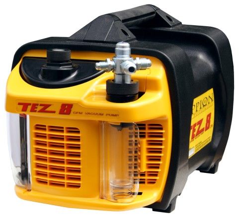
EPA Section 608 Preparatory Manual

         Stratospheric Ozone Depletion
         The introduction of Chlorofluorocarbons (CFCs) and Hydrochlorofluorocarbons (HCFCs) have
         dramatically changed our lifestyles. ASHRAE’s safety classifications do not consider a
         refrigerant’s environmental effects. Little did we know that the use and release of these
         compounds into the atmosphere would have far reaching, long-term effects on our environment.
         The greatest effect is in the stratosphere, which is far removed from the Earth's surface.

         The stratosphere, located between 7 and 30 miles above sea level, is comprised of ozone
         and other gases. The ozone layer is the Earth's security blanket. An ozone molecule, (O3),
         which consists of 3 oxygen atoms, protects us from harmful ultraviolet radiation from the Sun,
         and helps maintain stable Earth temperatures.
         Stratospheric ozone depletion is a global issue that can lead to problems such as crop loss,
         skin cancer, increased eye diseases such as cataracts and reduced plankton and other
         microscopic marine life.
         CFCs (chlorine, fluorine & carbon) and HCFCs, (hydrogen, chlorine, fluorine & carbon), which
         contain chlorine, have been found in air samples taken from the stratosphere. When CFCs and
         HCFCs, are released into the atmosphere their chlorine content causes depletion of the
         ozone layer. When a chlorine atom encounters an ozone molecule, it takes one Oxygen atom
         from the ozone forming a compound called chlorine monoxide (CIO), leaving an oxygen O 2
         molecule behind. The chlorine monoxide will collide with another ozone molecule, releasing its
         Oxygen atom, forming two O2 molecules, leaving the chlorine free to attack another ozone
         molecule. A single chlorine atom can destroy up to 100,000 ozone molecules.
         There has been some controversy over the subject of ozone depletion. Some believed that the
         chlorine found in the stratosphere comes from natural sources such as volcanic eruptions.
         However, air samples taken over erupting volcanoes show that volcanoes add only small
         quantities of chlorine to the atmosphere compared to the amount of chlorine added to the
         atmosphere from chlorine-containing refrigerants. In addition, the rise in the amount of chlorine
         measured in the stratosphere over the past four decades matches the rise in the amount of
         Fluorine, which has different natural sources than chlorine over the same period. Also, the rise
         in the amount of chlorine measured by NASA and other agencies in the stratosphere over the
         past twenty years matches the rise in CFC and HCFC emissions over the same period. The
         evidence is clear, chlorine containing refrigerants have changed the natural balance, thus
         depleting the ozone layer.
         Unlike other chlorine compounds and naturally-occurring chlorine, the chlorine in CFCs and
         HCFCs will neither dissolve in water nor break down into compounds that dissolve in water so
         they do not rain out of the atmosphere.
         HFCs are made up of Hydrogen, Fluorine and Carbon. They do not contain chlorine that
         effects the ozone layer, but most HFCs have a high Global Warming Potential (GWP).
         Ozone Depletion Potential
         Ozone Depletion Potential (ODP) is a measurement of a substance such as CFC’s and HCFC's
         ability to destroy ozone, and ranges from 0 to 1. CFCs have the highest ODP. HFCs
         (Hydrofluorocarbons/R-134a, R-32, & 400 series blends) and HFOs (hydrofluoroolefins/ R-1234yf,
         1234ze & 1233zd) do not contain chlorine and have an Ozone Depletion Potential of zero.
         Greenhouse Gases
         Greenhouse gases (GHGs) warm the Earth in two ways; by absorbing energy, slowing the rate
         at which it escapes to space and by acting like a blanket insulating the Earth. Examples of
         greenhouse gases and their effects on the atmosphere are as follows:
         Carbon dioxide (CO 2): CO2 is a natural gas, created through respiration and absorbed
         through photosynthesis, a relatively balanced cycle. The addition of man-made CO2 creates
         an overabundance and results in excess GHGs that enter the atmosphere as a result of
         burning fossil fuels (coal, natural gas, and oil), solid waste, wood/products, and is the result

8                                                                             ©Esco Institute 2018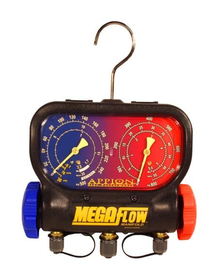
EPA Section 608 Preparatory Manual

of certain chemical reactions such as cement manufacturing. Carbon Dioxide is used as a
very high-pressure refrigerant (R-744) with zero (0) ODP and a Global Warming Potential
(GWP) of one (1). R-744 is used primarily in commercial and industrial process systems
and does not require Section 608 certification for purchasing or servicing. Natural
refrigerants such as R744 (carbon dioxide) that do not pose a threat to health or the
environment according to EPA may be released back into the environment.

Flammable refrigerants: Equipment with flammable refrigerants requires a red color marking on
all process tubes, service connections, and pipes through which a flammable refrigerant passes.
The color marking must extend one inch in both directions from service locations. When propane
(R-290) is used as refrigerant, it must meet the purity standards set for HVACR equipment.
Propane purchased for grilling contains impurities which will damage refrigeration equipment.
Propane and Isobutane are examples of “A3” flammable refrigerants that do not require recovery.
Propane, Butane and other Hydrocarbon refrigerants are also known as HC refrigerants.

Fluorinated gases: Hydrofluorocarbons, perfluorocarbons, sulfur hexafluoride, and nitrogen
trifluoride are synthetic, powerful greenhouse gases that are emitted from a variety of industrial
processes. Fluorinated gases such as CFCs, HCFCs and HFCs are referred to as high Global
Warming Potential gases ("High GWP gases").

R-134a: (Tetrafluoroethane) is an HFC with an ozone depletion potential (ODP) of zero (0)
and global warming potential (GWP) 1,430 times greater than carbon dioxide. R-134a is a
medium-range pressure refrigerant used in auto, domestic refrigeration and commercial
industries.

R-410A: (Hydrofluorocarbon) is a high-pressure, HFC refrigerant with an ODP of zero (0) and
global warming potential (GWP) 2,090 times greater than carbon dioxide. R-410A is a near
azeotrope refrigerant that does not fractionate during phase change in HVACR equipment.
One disadvantage of R-410A is the operating pressure is approximately 50% higher than R-22
and cannot be considered as a replacement for retrofitting existing systems.

R-1234yf: (Tetrafluoropropene) R-1234yf is a medium pressure, HFO refrigerant with an
(ODP) of 0 and global warming potential (GWP) only 4 times greater than carbon dioxide.

ASHRAE has grouped refrigerants by Class A
(safest) or B, depending on their toxicity level to
humans. Flammability is indicated by a 1 (no
flammability), 2 (low flammability), or 3 (high
flammability).

Clean Air Act
The United States Environmental Protection
Agency (EPA) regulates Section 608 of the
Federal Clean Air Act which establishes the
rules for regulating all Class I (Ozone
Depleting Substances such as CFCs), Class II
(HCFCs), and substitute refrigerants. Failure to
comply could cost you and your company.

Companies and or service technicians who violate Clean Air Act provisions may lose their
certification, be required to appear in Federal Court and be fined up to $44,539 per day, per
violation. The EPA may require technicians to demonstrate the ability to properly perform
refrigerant recovery/recycling procedures. Failing to demonstrate these skills can result in
revocation of certification. State and local jurisdictions may impose regulations that are equal
to or greater than those under the EPA’s Section 608. Technicians not following stricter state
and local government’s requirements may lead to other penalties.

   ©Esco Institute 2018                                                                              9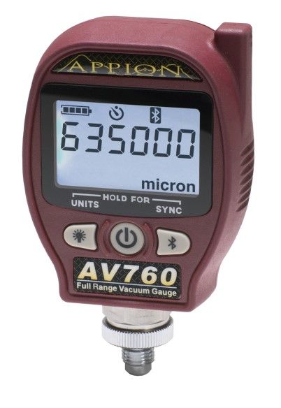
EPA Section 608 Preparatory Manual

         It is a violation of Section 608 to:
         • Falsify or fail to keep required records.
         • Fail to reach required evacuation level prior to opening or disposing of appliances.
         • Knowingly release (vent) ozone depleting and substitute refrigerants (such as CFCs, HCFCs
              or HFCs) while maintaining, installing, repairing or disposing of appliances or industrial
              process refrigeration with the exception of de-minimus releases.
         • Service, maintain, or dispose of appliances designed to contain refrigerants without being
              appropriately certified.
         • Fail to recover regulated refrigerants before opening or disposing of an appliance.
         • Fail to have an EPA approved recovery device, equipped with low loss fittings that
              automatically close or have manually operated shut-off valves on the hoses.
         • Add nitrogen to a fully charged system, for the purpose of leak detection, and thereby
              cause a release of the mixture.
         • Dispose of a disposable cylinder without first recovering (to 0 psig) any refrigerant
              remaining in the cylinder. (Refrigerant must be recovered from the cylinder, the cylinder
              must be rendered useless, and then the metal cylinder can be recycled.)
         • Release refrigerant during vandalism or theft of any HVACR equipment.

         It is the responsibility of the final person in the disposal chain to ensure that refrigerant has
         been removed from appliances before scrapping.
         Technicians disposing of mid-sized appliances with 5-50 pounds of refrigerant must keep the
         following records:
                 • The location, date of recovery, and type of refrigerant recovered for each disposed
                     appliance.
                 • The quantity of refrigerant, by type, recovered from disposed appliances in each
                     calendar month.
                 • The quantity of refrigerant, and type, transferred for reclamation or destruction, the
                     person / company to whom it was transferred, and the date of the transfer.

         Montreal Protocol
         Following several years of negotiations, an international agreement (treaty) regulating the
         production and use of CFCs, HCFCs, halons, methyl chloroform and carbon tetrachloride
         entered into force in mid-1989. Known as The Montreal Protocol, this landmark agreement
         initially required a production and consumption freeze. The Montreal Protocol called for a
         stepwise reduction and eventual production phase-out of various ozone depleting substances
         (ODS) in developed countries. In the United States, CFCs were the first substance group that
         was phased-out of production. Some HCFC refrigerants are scheduled for phase-out as early as
         2020, and by 2030 all HCFCs will be phased-out. When virgin supplies of restricted refrigerants
         are depleted, future supplies will come from only recovered, recycled, or reclaimed
         refrigerants.

         The Three Rs (Recover - Recycle - Reclaim)
         The processes of recovery, recycling, and reclaiming sound similar, but they are quite different.
         Recover: Remove refrigerant, in any condition, from a system and store it in an external
         container to be put back into the same system, recycled, or reclaimed.
         Recycle: Clean refrigerant by separating the oil from the refrigerant and removing moisture
         and other contaminants from the refrigerant by passing it through one or more filter driers.
         Recycled refrigerants may be placed back into the same system they came from or another
         system that is owned by the same owner.
         Reclaim: Process refrigerant to a level equal to new (virgin) product specifications as
         determined by chemical analysis. Reclaimed refrigerants must meet AHRI 700 Standards
         before they can be reused or sold to another user.

10                                                                             ©Esco Institute 2018
EPA Section 608 Preparatory Manual
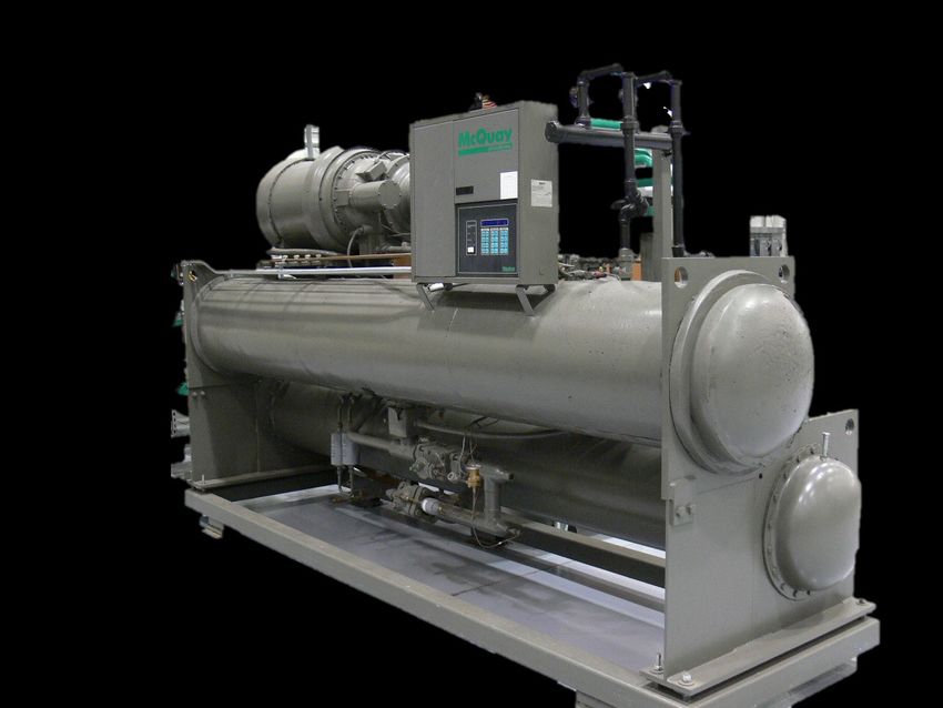
Recovery Devices
Refrigerant recovery and/or recycling equipment manufactured after November 15, 1993 must be
certified and labeled by an EPA approved equipment testing organization to meet EPA
standards.
There are two basic types of recovery devices:
1) “System-dependent” which captures refrigerant with the assistance of components in the
appliance from which refrigerant is being recovered. (Figure 4)
2) "Self-contained” which has its own means to draw the refrigerant out of the appliance.
(Figure 5)
Figure 4. Recovery Bag 12 oz. only Figure 5. Recovery Unit
Courtesy of Appion Inc.
Sales Restriction
The sale of CFC and HCFC refrigerants has been restricted to certified technicians since
November 14, 1994. The sale of HFC and HFO refrigerants are restricted to certified technicians
as of January 1, 2018. Only technicians certified under Section 609 of the Clean Air Act (Motor
Vehicle Air Conditioning) are allowed to purchase refrigerants in containers smaller than 20 lbs.
CFCs or HCFCs can be used for servicing a system that uses the refrigerant after the
phaseout. CFCs or HCFCs cannot be used in new equipment.
Substitute Refrigerants and Oils
Our industry is in a constant state of change. New refrigerants, blends of older refrigerants
and different oils have appeared in the field. The potential to effect the internal components
or oxidize the copper tubing must be evaluated. The EPA must review and approve new
refrigerants before they are introduced for use in HVACR equipment. The Significant New
Alternatives Policy program (SNAP) identifies and evaluates substitute refrigerants. EPA's
decision on the acceptability of new substitutes proposed by manufacturers, formulators, or
users is based primarily on the potential human health and environmental risks posed by the
substitutes as compared to other substitutes available for a particular end-use. EPA's
classifications of decisions on alternative substitutes may be listed as:
• Acceptable
• Acceptable subject to use conditions
• Acceptable subject to narrowed use limits
• Unacceptable alternatives
R-134a is an HFC and was considered ozone friendly. R-134a was the leading candidate for
CFC R-12 retrofit, but it is not a ‘drop-in’ substitute. In actuality, there is no such thing as a “drop-
in” refrigerant, but some refrigerants can be used in most compatible systems by following
appropriate retrofit procedures. HFC refrigerants will not mix with most refrigerant oils. The oils
used with HFC and HFO HVACR systems are esters. Esters cannot be mixed with other oils.
When retrofitting HCFC systems, polyolester (POE) type oil is commonly used as it can tolerate a
small percentage of other types of oil. It is also important to remember that, when leak testing an
HFC system, use pressurized nitrogen with only a trace amount of refrigerant vapor. In order to
avoid contamination use the same refrigerant as the system charge. This is not considered to be
a refrigerant that must be recovered.
©Esco Institute 2018 11EPA Section 608 Preparatory Manual
There are several refrigerant blends commonly in use. Some blends are called ternary, which means
they are a three-part blend. HCFC-22 and HCFC ternary blends are used with a synthetic alkylbenzene
lubricant. Make certain you are using the correct oil for the particular refrigerant. Most refrigerant oils are
hygroscopic. Hygroscopic oil has a high affinity for water. An oil sample should be taken and analyzed if
a system has had burned compressor winding failure or a major leak, allowing moisture to enter the
system.
Refrigerant blends are made up of two or more single component refrigerants. Depending on how
strongly the refrigerant molecules are attracted to each other, they may be classified as azeotropic or
zeotropic. An azeotropic mixture acts like a single component refrigerant over its entire temperature/
pressure range. An azeotrope does not have a temperature glide, whereas, a zeotropic blend behaves
like a mixture of the individual components with predictable properties based on combinations of the
original refrigerant’s properties. Temperature glide refers to the range of boiling or condensing
temperature points that a refrigerant blend might experience at a specific pressure. Refrigerant
fractionation can occur from a continuous leak due to the difference in pressures from the combined
refrigerants.
The R-400 series of refrigerants are zeotropic blends that can leak from a system at uneven rates due to
different vapor pressures which can effect the percentage of each refrigerant remaining in the system.
The proper charging method for R-400 series blended refrigerants is to weigh the refrigerant into the high
side of the system as a liquid. When adding refrigerant to an undercharged system, liquid refrigerant is
throttled into the low side with the system operating.
Zeotropic blends use Bubble and Dew points to indicate condensing and evaporation temperatures on a
pressure temperature saturation chart. Bubble point is used when charging by condenser subcooling and
Dew point is used for charging by suction or evaporator superheat. The relationship of pressures and
temperatures are based on the refrigerant’s temperature glide. Temperature glide can range a few tenths
of a degree to 12 degrees or more.
Even though the pressure temperature relationship, and the operating characteristics may be almost the
same, the refrigerants cannot be interchanged. Due to flammability of some of the HC’s and HFO’s
equipment must be designed to handle the refrigerant. Therefore, EPA regulates the maximum amount
of refrigerant that can be used in the new systems by their type and use.
Recovery Techniques
EPA regulations require a service aperture or process stub on all hermetically-sealed appliances that use
a regulated refrigerant in order to make it easier to recover refrigerant.
When servicing a system, if you discover that the refrigerant is contaminated, two or more refrigerants
have been mixed in a system, you must recover the mixture into a separate tank to be turned in for
reclamation. It is important NOT to mix different refrigerants in the same recovery tank because the
mixture may be impossible to reclaim. Recover only one type of refrigerant into a recovery tank. The
number of recovery tanks required by a person or company depends on the variety of equipment worked
on and their types of refrigerants.
If a strong odor is detected during the recovery process, a compressor burn-out has likely occurred.
When recovering refrigerant from a system that experienced a compressor burn-out, watch for signs of oil
contamination. The contamination may be in the oil as sludge, moisture and acid. After recovering
refrigerant, if nitrogen is used, with or without a flushing solution to flush debris out of the system, the
nitrogen may be legally vented. A suction line filter drier should be installed to trap any debris that may
damage the new compressor.
The size of the equipment, amount of moisture, length of the hose between the unit being recovered from
and the recovery machine, and the ambient temperature can all effect the efficiency of the recovery
process. Long hoses will cause excessive pressure drop, increased recovery time, and have a potential
for increased emissions or venting from the recovery machine. Excessive venting of the recovery
machine or cylinder is illegal. Since all refrigerants have a pressure temperature relationship, the lower
the ambient temperature surrounding the equipment being serviced, the slower the recovery rate.
12 ©Esco Institute 2018EPA Section 608 Preparatory Manual
After completing the transfer of liquid refrigerant between a recovery unit and a refrigeration
system, you should guard against trapping liquid refrigerant between the service valves.
Recovered refrigerant may not meet AHRI standard for virgin refrigerant therefore it can only be
reused in the same system or another system of the same owner. It cannot change ownership.
Leak Detection
In order to determine the general area of a leak, use an electronic or ultrasonic leak detector
after pressurizing the system with nitrogen and a trace amount of refrigerant. Once the general
area of the leak is located, the use of soap bubbles will aid in pinpointing the leak. Finding and
repairing leaks in a system will conserve refrigerant for future use.
When leak testing any flammable hydrocarbon or HFO refrigerant, install a fresh filter-drier and
complete a standing-pressure leak check at the maximum system pressure before evacuating to
500 microns or lower.
Two verification tests are required when an appliance containing 50 pounds of refrigerant or
more has triggered the leak rate threshold and subsequently has been repaired. One must be
performed before the appliance is recharged and one after the appliance returns to normal
operating conditions.
Section 608 of the Clean Air Act uses three categories to define applicable leak rates for
systems other than small appliances.
Industrial Process Refrigeration (IPR), refrigeration equipment used in agriculture, crop
production, oil and gas extraction, ice rinks, manufacture of frozen food, dairy products, food and
beverages, ice, petrochemicals, chemicals, machinery, medical equipment, plastics, paper, and
electronics.
Commercial Refrigeration, refrigerated warehousing and storage facilities, supermarkets,
grocery stores, warehouse clubs, supercenters, convenience stores, and refrigerated transport.
Comfort Cooling, air conditioning equipment, and others not listed.
Note: When an appliance is designed for multiple uses, the category will be considered
industrial process refrigeration equipment if 50 percent or more of its operating capacity
is used for industrial process refrigeration.
Dehydration
The reason for dehydrating a refrigeration system is to remove water and water vapor and it is
important to follow proper dehydration procedures. If moisture is allowed to remain in an operating
refrigeration system, hydrochloric and hydrofluoric acids may form. Evacuation of a system is the
suggested method of dehydration. It is not possible to over evacuate a system. Most
manufacturers require an evacuation to 500 microns or lower which can be measured with a
micron gauge (Figure 6).
Never evacuate a system to the ambient air without first following proper recovery
procedures and attaining the mandated recovery level. (See Table 1, page 16).
The factors that affect the speed and efficiency of evacuation are; size of equipment
being evacuated, ambient temperature, amount of moisture in the system, the size of
the vacuum pump and suction line. In addition, vacuum lines should be equal to or
larger than the pump intake connection. The piping connection to the pump should be
as short a length as possible and as large in diameter as possible. The system vacuum
gauge should be connected as far away from the vacuum pump as possible.
Measuring a system’s vacuum should be done with the system isolated and the
vacuum pump turned off.
Figure 6. Vacuum Gauge
Courtesy of Appion Inc.
©Esco Institute 2018 13EPA Section 608 Preparatory Manual
Figure 7. Vacuum Manifold Figure 8. Vacuum Pump
Courtesy of Appion Inc. Courtesy of Appion Inc.
A system that will not hold a vacuum probably has a leak. During evacuation you may wish to heat
the refrigeration system to decrease dehydration time. Tapping a compressor with a rubber mallet
will aid in releasing trapped refrigerant from the oil.
Never operate the compressor while the system is in a deep vacuum; internal electrical arcing
could occur, burning the motor windings.
Dehydration is complete when the vacuum gauge shows that you have reached and held the
required vacuum.
Recovery Cylinders
Recovery cylinders differ in many ways from disposable cylinders. Disposable cylinders are used
only with virgin refrigerant and may NEVER be used for recovery. If the refrigerant in a recovery
cylinder is suspected to be contaminated, a pressure reading of the cylinder should be taken and
compared to a pressure temperature chart.
Recovery cylinders are specifically designed to be refilled. Recovery cylinders have 2 ports, one
liquid and one vapor. Care must be taken not to overfill or heat these cylinders, as it could
cause an explosion. The EPA requires that a refillable refrigerant cylinder MUST NOT BE
FILLED ABOVE 80% of its capacity by weight, and that the safe filling level can be controlled
by mechanical float devices, electronic shut off devices (thermistors), or weight. Refillable
cylinders must be hydrostatically tested and date stamped every 5 years.
Refillable cylinders must be Department of
Transportation (DOT) approved. Approved refrigerant Liquid
recovery cylinders can easily be identified by their Vapor
colors; yellow tops and grey bodies. All refrigerant
recovery cylinders should be inspected for rust. If a
refillable cylinder shows signs of rust or appears to
have been heated or damaged in any way, it should be Yellow Top
reduced to 0 psig by recovering to another cylinder and
discarded. Reclaimers will not accept visibly burned
recovery tanks.
Safety
The EPA is concerned not only with the prevention of Grey
refrigerant venting, but with the technician’s overall safety. Body
When handling and filling refrigerant cylinders or
operating recovery or recycling equipment, you should
wear safety glasses, protective gloves, and follow all
equipment manufacturer’s safety precautions. Make sure
your recovery machine is grounded when in use, Figure 9. Recovery Tank
especially when recovering a flammable refrigerant.
14 ©Esco Institute 2018EPA Section 608 Preparatory Manual When pressurizing a system with nitrogen, you should always charge through a pressure regulator and a relief valve in the downstream line from the pressure regulator. Relief valves MUST NOT be installed in series. If corrosion build-up is found within the body of a relief valve, the valve MUST be replaced. When leak checking a system, NEVER pressurize the system with oxygen or compressed air. When mixed with refrigerants, oxygen or compressed air can cause an explosion. To determine the safe pressure for leak testing, check the equipment data plate for the maximum low-side test pressure value. When using recovery cylinders and equipment with Schrader valves, it is critical to inspect the Schrader valve core for leaks, bends, and breakage. Replace damaged valve cores to prevent leakage, and always cap Schrader ports to prevent accidental depression of the valve core. NEVER heat a refrigerant cylinder with an open flame. Do not cut or braze refrigerant lines on a charged unit. In the event of a “large” release of refrigerant in a confined area, Self-Contained Breathing Apparatus (SCBA) is required. If a large leak of refrigerant occurs in an enclosed area, and SCBA is not available, IMMEDIATELY VACATE AND VENTILATE the area. In large quantities, all refrigerants can cause suffocation because they can displace oxygen. Inhaling refrigerant vapors or mist may cause heart irregularities, unconsciousness, and oxygen deprivation leading to death (asphyxia). NEVER expose refrigerants to open flames or glowing hot metal surfaces. At high temperatures, refrigerants decompose and form acids. Hydrochloric acid is formed if the refrigerant contains chlorine and hydrofluoric acid is formed if the refrigerant contains fluorine. If oxygen is also present, it is possible to form carbon monoxide, carbon dioxide and phosgene gas. If a hydrocarbon refrigerant is released into a space, an explosion can occur if the refrigerant concentration is above the Lower Flammability Limit and below the Upper Flammability Limit with an ignition source. Always review the Safety Data Sheets (SDS) when working with any solvents, chemicals, or refrigerants. Silicone elastomers, for use in seals and gaskets, are not compatible with HFO refrigerants. Only use an alcohol spray to remove or clean ice from a sight glass when required. Shipping & Transporting Before shipping any used refrigerant cylinders, check that the cylinder meets DOT standards. Complete the shipping paperwork including the number of cylinders of each refrigerant, and properly label the cylinder with the type and amount of refrigerant before it is returned for reclaiming. Cylinders should be transported in an upright position. Each cylinder must be marked with a DOT classification tag indicating it is either a non-flammable or flammable gas. Some states may require special shipping procedures to be followed based on their classification of used refrigerants. Check with the DOT in your state. ©Esco Institute 2018 15
Ozone       Global
                                                                                                                                                              EPA
                                                                                Depletion   Warming                                                                     ASHRAE

16
                       Ref. No.   Type            Name/Composition                                                       Common Use                         Pressure
                                                                                Potential   Potential                                                                    Class
                                                                                                                                                             Range
                                                                                 (ODP)       (GWP)

                        R-11      CFC           Trichlorofluoromethane          1 (Base)      4000           Air-conditioning Chillers (Phased Out)           Low         A1

                        R-12      CFC          Dichlorodifluoromethane             1         10900      Automotive, Domestic, Commercial (Phased Out)       Medium        A1

                        R-22      HCFC        Monochlorodifluoromethane           .055        1810                      Air-conditioning                      High        A1

                        R-123     HCFC          Dichlorotrifluoroethane          0.012         76                     Commercial Chillers                     Low         B1

                                  CFC +      Monohloropentafluoroethane/
                        R-502                                                     .283        4657               Low-temperature Commercial                   High        A1
                                  HCFC        Monohlorodifluoromethane

                       R-134a     HFC             Tetrafluoroethane                0          1430             Automotive, Domestic, Commercial             Medium        A1

                                          Pentafluoroethane, Trifluoroethane,                            Medium and low-temperature commercial and
                       R-404A     HFC                                              0          3920                                                            High        A1
                                                  Tetrafluoroethane                                                       industrial
                                                                                                                                                                                                                                                                                            EPA Section 608 Preparatory Manual

                                          Difluoromethane, Pentafluoroethane,
                       R-407C     HFC                                              0          1770                Air-conditioning R-22 retrofit              High        A1
                                                   Tetrafluoroethane

                       R-410A     HFC     Difluoromethane, Pentafluoroethane       0          2090                      Air-conditioning                      High        A1

                                          Pentafluoroethane, Trifluoroethane,                            Retrofit for medium & low temp., R-22,R-407C,
                       R-422B     HFC                                              0          3143                                                            High        A1
                                                      Isobutane                                                     R-502 & other HCFC blends
                                                                                                                                                                                                                           Core, Types I, II & III.

                                                                                                          Domestic Refrigerators & Freezers, Vending
                        R-441      HC     Ethane, Propane, Butane, Isobutane       0           0           machines, & Self contained Commercial              High        A3
                                                                                                                   Refrigerators & Freezers

                        R-170      HC                   Ethane                     0           6                         Manufacturing                      Very High     A3

                        R-290      HC                  Propane                     0           3         Commercial & Industrial Process Refrigeration        High        A3

                                                                                                           Domestic Small Appliances, Commercial &
                       R-600a      HC                 Isobutane                    0           3                                                            Medium        A3
                                                                                                               Industrial Process Refrigeration

                        R-744                      Carbon Dioxide                  0        1 (Base)     Commercial & Industrial Process Refrigeration      Very High     A1

                                                                                                        Air-conditioning, Commercial & Industrial Process
                        R-717                         Ammonia                      0           0                                                              High        B2
                                                                                                                           Refrigeration

                       R-1234yf   HFO         Hydrogen, Fluorine, Carbon           0           4                          Automotive                        Medium       A2L
                                                                                                                                                                                 The following table lists refrigerants with characteristics that may be covered in each of the sections;

                       R-1234ze   HFO         Hydrogen, Fluorine, Carbon           0           6             New Chillers, heat pumps, and vending          Medium       A2L

©Esco Institute 2018
                       R-1233zd   HFO         Hydrogen, Fluorine, Carbon           0           1                 New Chillers & Foam blowing                  Low        A2L
EPA Section 608 Preparatory Manual
Persons handling refrigerant during maintenance, service, or repair of Small Appliances
must be certified as either a Type I Technician or as a Universal Technician, with the
exception of motor vehicle air conditioning (MVAC). The EPA definition of a small
appliance includes; products manufactured, charged, and hermetically sealed in a factory
containing five pounds or less of refrigerant. Split-systems may not be serviced by Type I
technicians. The sale of regulated refrigerants such as CFCs, HCFCs, HFCs and HFOs is
restricted to certified technicians.
Note: MVAC certification is covered under Section 609 of the Clean Air Act.
Equipment Requirements
Passive (system dependent) or active (self-contained) recovery equipment must be certified
by an EPA-approved testing laboratory, (example, U.L. or E.T.L). When using recovery
equipment manufactured after November 15, 1993, it must be able to recover 90% of the
refrigerant when the compressor in the appliance is functioning, or 80% of the
refrigerant when the appliance’s compressor is not functioning. Evacuating the appliance
to four inches of mercury vacuum is low enough to satisfy the rules.
All recovery equipment must be equipped with low-loss fittings that can be manually closed, or
close automatically, when hoses are disconnected, to minimize the refrigerant loss.
Note: Isobutane (R-600a), an HC, is approved as a substitute refrigerant for new
household refrigerators, freezers, and combination refrigeration/freezers. R-600a cannot
be used for retrofitting a small appliance.
Leak Repair Requirements
The EPA does not require leak repair for small appliances, but leaks should be repaired
whenever possible to conserve refrigerant. Make sure the valve cores are tight and the caps
are on the Schrader ports to prevent accidental depression and leaking from the valve cores.
Recovery Techniques
Before beginning a refrigerant recovery procedure, it is necessary to know the type of refrigerant
that is in the system. After recovery, if contaminants are present in the oil, the system will have
to be flushed with a cleaning solvent designed for the type of refrigerant in the system. To speed
up the process, recover from both the low and high side of the system.
If a reclamation facility receives a tank of mixed refrigerant, they may refuse to process the
refrigerant and destroy it at the owner's expense. Do not mix refrigerants in a recovery tank.
Self-contained (active) recovery equipment has its own means of pumping and removing
refrigerant from an appliance and is capable of reaching the required recovery levels whether
or not the appliance compressor is operable. Self-contained recovery equipment pumps the
refrigerant into a recovery tank. Before operating a self-contained recovery machine, make
sure that the tank inlet valve is open, and that the recovery tank does not contain excessive
non–condensables (air). Obtaining accurate pressure and temperature measurements of
refrigerant inside a recovery cylinder is necessary to detect excessive non-condensables and
the type of refrigerant. The only way to identify the refrigerant is to measure the refrigerant
pressure accurately at a stable, known temperature. Air in a refrigeration system will cause
higher discharge pressures in the system and recovery equipment. Follow the operating
instructions supplied by the recovery equipment manufacturer regarding purging of non-
condensables. All refrigerant recovery equipment should be checked for oil level and
refrigerant leaks on a daily basis, and replace filters as required. When using a recovery
machine on very low horsepower systems such as domestic refrigerators and freezers that
contain a few ounces of refrigerant, it is important to recover the refrigerant from the low and
high sides to prevent oil migration.
©Esco Institute 2018 17EPA Section 608 Preparatory Manual
A system-dependent (passive) recovery process for small appliances captures refrigerant into
Type I
a non-pressurized container. This may be a special plastic “bag” container large enough to
contain a few ounces of refrigerant. A standard vacuum pump can only be used as a recovery
device in combination with a non-pressurized container. The vacuum pump is only used to
reduce the pressure of a recovery cylinder or container into a vacuum before the recovery
process.
With system-dependent recovery equipment, some special procedures may be necessary
depending on the condition of the appliance. System dependent devices may only be used on
appliances containing 15 lbs. of refrigerant or less. When using a system-dependent recovery
process on an appliance with an operating compressor, run the compressor and recover from
the high side of the system. Usually, one access fitting on the high side will be sufficient to
reach the required recovery rate as the appliance compressor should be capable of pumping
the refrigerant to the high side.
If the appliance has a non-operating compressor, access to both the low and high side of the
system may be necessary. In order to achieve the required recovery efficiency, it will be
necessary to take measures such as heating and tapping the compressor several times to help
release trapped refrigerant from the compressor oil, turning on the defrost heater to warm the
evaporator. Because appliances with non-operating compressors cannot always achieve
desired evacuation level utilizing system-dependent recovery equipment, the EPA requires
technicians to have at least one self-contained recovery device available at the shop to
recover refrigerant from systems with non-operating compressors. The exception to this rule is
persons working on their own small appliances. The rule is stated as: “Persons who maintain,
service, repair, or dispose of only appliances that they own and that contain pumpout units are
exempt from the requirement to use certified, self-contained recovery and/or recycling
equipment.”
Small appliances are equipped with a straight piece of tubing, called a process tube, onto
which a piercing type access fitting can be installed. When installing an access fitting onto a
sealed system, the fitting should be leak tested before proceeding with recovery. It is generally
recommended that solderless piercing type valves only be used on copper or aluminum tubing
material. These fittings tend to leak over time and should not be left on an appliance as a
permanent service fixture. If, after installing an access fitting, you find that the system pressure
is 0 psig, do not begin the recovery process. If a strong odor is detected during the recovery
process, a compressor burn-out has likely occurred. When recovering refrigerant from a
system that experienced a compressor burn-out, watch for signs of contamination in the oil.
After recovering refrigerant, if nitrogen is used to flush debris out of the system, the nitrogen
may be legally vented.
Small appliances used in campers or other recreational vehicles may use refrigerants such as
Ammonia, Hydrogen, or water, and therefore should not be recovered using current recovery
equipment.
When filling a charging cylinder with a regulated refrigerant, the refrigerant vapor that is vented
off the top of the cylinder must be recovered.
Safety & Shipping
Safety and shipping requirements are covered in the Core section of this manual.
Note: None of the hydrocarbon refrigerants are approved for retrofit into existing
household refrigerators. The appliance must designed for a hydrocarbon refrigerant
and labeled as to the type of refrigerant. This label must be placed on the outside of
the appliance in view of the service location.
18 ©Esco Institute 2018EPA Section 608 Preparatory Manual Technicians maintaining, servicing, repairing or disposing of high-pressure to very high- pressure appliances, except small appliances and motor vehicle air conditioning systems (MVAC), must be certified as a Type II Technician or a Universal Technician. Leak Detection After the installation of any type of system, the unit should first be pressurized with nitrogen (an inert gas) and leak checked. To determine the general area of a leak use an electronic or ultrasonic leak detector. Once the general area of the leak is located the use of soap bubbles will pinpoint the leak. In order to use an electronic leak detector on a system that is pressurized with nitrogen, a trace of refrigerant must be added to the system. A refrigeration unit using an open compressor that has not been used in several months is likely to leak from the rotating shaft seal. During a visual inspection of any type of system, traces of oil are an indication of a refrigerant leak. Excessive superheat caused by a low refrigerant charge is also an indication of a leak in a high-pressure system. Leak Repair Requirements EPA regulations require all comfort cooling (air conditioning) appliances containing 50 lbs. or more of a regulated refrigerant to have annual leak inspections to determine if the appliance is leaking. The appliance must be repaired within 30 days when the annual leak rate exceeds 10% of the total charge. A leak-test must be performed after each repair attempt, and a follow-up verification leak-test must be conducted within 10 days of the repair. The time frame for mandatory leak repair can only be extended by a certified service technician. If the leaking appliance is not going to be repaired, it must be retired or mothballed. When an appliance is mothballed, the leaking component of the system must be isolated and the refrigerant recovered to prevent further leaking. Type II appliances that will not be repaired must be retrofitted or retired in 12 months. If the appliance is using an exempt refrigerant then the owner has 18 months to retire the leaking system. All commercial and industrial process refrigeration (IPR) containing more than 50 lbs. of refrigerant MUST be repaired when the annual leak rate is exceeds 20% for commercial appliances and 30% for IPR. When one appliance is used for both industrial process refrigeration and other applications, it will be considered industrial process refrigeration equipment when 50% or more of its operating capacity is used for industrial process refrigeration. Commercial refrigeration appliances and IPR with a full charge of 500 pounds or more of a regulated refrigerant will require a leak inspection to be conducted every three months unless a refrigerant leak monitoring system is installed or it has not exceeded the leak rate for four quarters. The total system refrigerant charge can be calculated by adding the charge for each component and the piping. Using the calculated charge, the leak rate percentage can be determined for the quantity of refrigerant added to a system that is new, retrofitted, or adjusted for seasonal variance. When an appliance containing 50 lbs. of a regulated refrigerant or more leaks 125% or more, the owner must submit a report to EPA describing efforts to identify leaks and repair. All records for leak inspections, initial verification, verification tests and records of recovered refrigerant from equipment with 5 to 50 lbs. must be kept for 3 years by the owner or operator. This includes the quantity of refrigerant, by type added, recovered from disposed appliances in each calendar month and quantity of refrigerant, by type, sent for reclamation or destruction. Topping off a system is considered adding refrigerant due to a leak and must be accounted for in the leak-rate calculation. ©Esco Institute 2018 19
EPA Section 608 Preparatory Manual

            Recovery Techniques
            Proper recovery techniques begin with the use of appropriate recovery equipment that has been
Type II
            certified by an EPA approved laboratory (UL or ETL) to meet or exceed AHRI Standards.

            Recovered refrigerants may contain acids, moisture, and oil. It is necessary to frequently check
            and change both the oil and filter on a recovery/recycling unit. Both recycling and recovery
            equipment using hermetic compressors have the potential to overheat when drawing a deep
            vacuum, because the unit relies on the flow of refrigerant through the compressor for cooling.
            Before using a recovery unit you should always check the service valve positions, the oil level of
            the recovery unit, and evacuate and recover any remaining refrigerant from the unit and receiver.

            Technicians working with multiple refrigerants, before recovering and/or recycling a different
            refrigerant, must purge the recover/recycle equipment by recovering as much of the first
            refrigerant as possible, change the filter, and evacuate. The only exception to this rule is for
            technicians working with HFCs who must provide a special set of hoses, gauges, vacuum
            pump, recovery or recovery/recycling machine, and oil containers to be used with HFCs only.

            Although recovering refrigerant in the vapor phase will minimize the loss of oil, recovering as
            much as possible in the liquid phase from the liquid line or receiver can reduce recovery time.
            The technician may choose to speed up the recovery process by packing the recovery cylinder
            in ice and/or applying heat to the appliance. After recovering liquid refrigerant, any remaining
            vapor is removed and condensed by the recovery equipment.

            Very large capacity recovery machines may have a water-cooled condenser to aid in faster recovery.
            The water-cooled condenser requires connection to a potable or municipal water supply.

            When performing refrigerant system service on an operating unit that has a receiver/storage
            tank, refrigerant should be pumped into the receiver. Refrigerant should be removed from the
            condenser outlet if the condenser is below the receiver. The compressor in a parallel-rack
            system with an open equalization connection must be isolated before recovering refrigerant.

            After recovery, refrigerant may be returned to the appliance from which it was removed or to
            another appliance owned by the same person without being recycled or reclaimed. The
            technician should always evacuate an empty recovery cylinder before transferring refrigerant
            to the cylinder. Quick couplers, self-sealing hoses, or hand valves should be used (as low-loss
            fittings) to minimize refrigerant release when hoses are connected and disconnected.

            Recovery Requirements
            Anyone that services, repairs, or disposes of Type I, II or III equipment must have recovery
            equipment and/or recycling equipment that is certified and labeled by an EPA-approved
            equipment testing organization to meet EPA Standards. The purchase of recovery equipment
            does not need to be reported to the EPA.

            After reaching the desired vacuum, the technician should wait a few minutes to see if the
            system pressure rises, indicating that there is still refrigerant in liquid form or in the oil.
            Appliances can be evacuated to atmospheric pressure (0 psig) if leaks make recovery
            (evacuation) to the prescribed level unattainable. System-dependent recovery equipment
            cannot be used on appliances containing more than 15 pounds of refrigerant.

            A “major repair,” according to EPA regulations, is defined as any maintenance, service or
            repair involving the removal of any or all of the following components: the compressor, the
            condenser, the evaporator or an auxiliary heat exchanger coil.

   20                                                                             ©Esco Institute 2018
You can also read