Unstructured Information Management Architecture (UIMA) Version 1.0 - OASIS Open
←
→
Page content transcription
If your browser does not render page correctly, please read the page content below
Unstructured Information Management
Architecture (UIMA) Version 1.0
OASIS Standard
2 March 2009
Specification URIs:
This Version:
http://docs.oasis-open.org/uima/v1.0/os/uima-spec-os.html
http://docs.oasis-open.org/uima/v1.0/os/uima-spec-os.doc (Authoritative)
http://docs.oasis-open.org/uima/v1.0/os/uima-spec-os.pdf
Previous Version:
http://docs.oasis-open.org/uima/v1.0/cs01/uima-spec-cs-01.html
http://docs.oasis-open.org/uima/v1.0/cs01/uima-spec-cs-01.doc (Authoritative)
http://docs.oasis-open.org/uima/v1.0/cs01/uima-spec-cs-01.pdf
Latest Version:
http://docs.oasis-open.org/uima/v1.0/uima-v1.0.html
http://docs.oasis-open.org/uima/v1.0/uima-v1.0.doc
http://docs.oasis-open.org/uima/v1.0/uima-v1.0.pdf
Technical Committee:
OASIS Unstructured Information Management Architecture (UIMA) TC
Chair(s):
David Ferrucci, IBM
Editor(s):
Adam Lally, IBM
Karin Verspoor, University of Colorado Denver
Eric Nyberg, Carnegie Mellon University
Related work:
This specification is related to:
OASIS Unstructured Operation Markup Language (UOML). The UIMA specification,
however, is independent of any particular model for representing or manipulating
unstructured content.
Declared XML Namespace(s):
http://docs.oasis-open.org/uima/ns/base.ecore
http://docs.oasis-open.org/uima/ns/peMetadata.ecore
http://docs.oasis-open.org/uima/ns/pe.ecore
http://docs.oasis-open.org/uima/ns/peService
Abstract:
Unstructured information may be defined as the direct product of human communication.
Examples include natural language documents, email, speech, images and video. The UIMA
specification defines platform-independent data representations and interfaces for software
components or services called analytics, which analyze unstructured information and assign
semantics to regions of that unstructured information.
uima-spec-v1.0 2 March 2009
Copyright © OASIS® 2008. All Rights Reserved. Page 1 of 99Status:
This document was last revised or approved by the UIMA TC on the above date. The level of
approval is also listed above. Check the ―Latest Approved Version‖ location noted above for
possible later revisions of this document.
Technical Committee members should send comments on this specification to the Technical
Committee‘s email list. Others should send comments to the Technical Committee by using the
―Send A Comment‖ button on the Technical Committee‘s web page at http://www.oasis-
open.org/committees/uima/.
For information on whether any patents have been disclosed that may be essential to
implementing this specification, and any offers of patent licensing terms, please refer to the
Intellectual Property Rights section of the Technical Committee web page (http://www.oasis-
open.org/committees/uima/ipr.php).
uima-spec-v1.0 2 March 2009
Copyright © OASIS® 2008. All Rights Reserved. Page 2 of 99Notices Copyright © OASIS® 2008-2009. All Rights Reserved. All capitalized terms in the following text have the meanings assigned to them in the OASIS Intellectual Property Rights Policy (the "OASIS IPR Policy"). The full Policy may be found at the OASIS website. This document and translations of it may be copied and furnished to others, and derivative works that comment on or otherwise explain it or assist in its implementation may be prepared, copied, published, and distributed, in whole or in part, without restriction of any kind, provided that the above copyright notice and this section are included on all such copies and derivative works. However, this document itself may not be modified in any way, including by removing the copyright notice or references to OASIS, except as needed for the purpose of developing any document or deliverable produced by an OASIS Technical Committee (in which case the rules applicable to copyrights, as set forth in the OASIS IPR Policy, must be followed) or as required to translate it into languages other than English. The limited permissions granted above are perpetual and will not be revoked by OASIS or its successors or assigns. This document and the information contained herein is provided on an "AS IS" basis and OASIS DISCLAIMS ALL WARRANTIES, EXPRESS OR IMPLIED, INCLUDING BUT NOT LIMITED TO ANY WARRANTY THAT THE USE OF THE INFORMATION HEREIN WILL NOT INFRINGE ANY OWNERSHIP RIGHTS OR ANY IMPLIED WARRANTIES OF MERCHANTABILITY OR FITNESS FOR A PARTICULAR PURPOSE. OASIS requests that any OASIS Party or any other party that believes it has patent claims that would necessarily be infringed by implementations of this OASIS Committee Specification or OASIS Standard, to notify OASIS TC Administrator and provide an indication of its willingness to grant patent licenses to such patent claims in a manner consistent with the IPR Mode of the OASIS Technical Committee that produced this specification. OASIS invites any party to contact the OASIS TC Administrator if it is aware of a claim of ownership of any patent claims that would necessarily be infringed by implementations of this specification by a patent holder that is not willing to provide a license to such patent claims in a manner consistent with the IPR Mode of the OASIS Technical Committee that produced this specification. OASIS may include such claims on its website, but disclaims any obligation to do so. OASIS takes no position regarding the validity or scope of any intellectual property or other rights that might be claimed to pertain to the implementation or use of the technology described in this document or the extent to which any license under such rights might or might not be available; neither does it represent that it has made any effort to identify any such rights. Information on OASIS' procedures with respect to rights in any document or deliverable produced by an OASIS Technical Committee can be found on the OASIS website. Copies of claims of rights made available for publication and any assurances of licenses to be made available, or the result of an attempt made to obtain a general license or permission for the use of such proprietary rights by implementers or users of this OASIS Committee Specification or OASIS Standard, can be obtained from the OASIS TC Administrator. OASIS makes no representation that any information or list of intellectual property rights will at any time be complete, or that any claims in such list are, in fact, Essential Claims. The names "OASIS" and ―UIMA‖ are trademarks of OASIS, the owner and developer of this specification, and should be used only to refer to the organization and its official outputs. OASIS welcomes reference to, and implementation and use of, specifications, while reserving the right to enforce its marks against misleading uses. Please see http://www.oasis-open.org/who/trademark.php for above guidance. uima-spec-v1.0 2 March 2009 Copyright © OASIS® 2008. All Rights Reserved. Page 3 of 99
Table of Contents
1    Introduction......................................................................................................................................... 6
  1.1 Terminology ...................................................................................................................................... 7
  1.2 Normative References ...................................................................................................................... 7
  1.3 Non-Normative References .............................................................................................................. 8
2    Basic Concepts and Terms ................................................................................................................ 9
3    Elements of the UIMA Specification ................................................................................................. 11
  3.1 Common Analysis Structure (CAS)................................................................................................. 11
  3.2 Type System Model ........................................................................................................................ 11
  3.3 Base Type System.......................................................................................................................... 13
  3.4 Abstract Interfaces .......................................................................................................................... 13
  3.5 Behavioral Metadata ....................................................................................................................... 14
  3.6 Processing Element Metadata ........................................................................................................ 15
  3.7 WSDL Service Descriptions ............................................................................................................ 16
4    Full UIMA Specification .................................................................................................................... 17
  4.1 The Common Analysis Structure (CAS) ......................................................................................... 17
     4.1.1 Basic Structure: Objects and Slots .......................................................................................... 17
     4.1.2 Relationship to Type System ................................................................................................... 17
     4.1.3 The XMI CAS Representation ................................................................................................. 18
     4.1.4 CAS Formal Specification........................................................................................................ 18
  4.2 The Type System Model ................................................................................................................. 19
     4.2.1 Ecore as the UIMA Type System Model .................................................................................. 19
     4.2.2 Type System Model Formal Specification ............................................................................... 19
  4.3 Base Type System.......................................................................................................................... 20
     4.3.1 Primitive Types ........................................................................................................................ 20
     4.3.2 Annotation and Sofa Base Type System ................................................................................. 20
     4.3.3 View Base Type System.......................................................................................................... 22
     4.3.4 Source Document Information ................................................................................................. 24
     4.3.5 Base Type System Formal Specification ................................................................................. 25
  4.4 Abstract Interfaces .......................................................................................................................... 25
     4.4.1 Abstract Interfaces URL .......................................................................................................... 25
     4.4.2 Abstract Interfaces Formal Specification ................................................................................. 26
  4.5 Behavioral Metadata ....................................................................................................................... 30
     4.5.1 Behavioral Metadata UML ....................................................................................................... 30
     4.5.2 Behavioral Metadata Elements and XML Representation ....................................................... 31
     4.5.3 Formal Semantics for Behavioral Metadata ............................................................................. 31
     4.5.4 Behavioral Metadata Formal Specification .............................................................................. 33
  4.6 Processing Element Metadata ........................................................................................................ 36
     4.6.1 Elements of PE Metadata ........................................................................................................ 36
     4.6.2 Processing Element Metadata Formal Specification ............................................................... 39
  4.7 Service WSDL Descriptions ............................................................................................................ 39
     4.7.1 Overview of the WSDL Definition ............................................................................................ 39
     4.7.2 Delta Responses ..................................................................................................................... 43
     4.7.3 Service WSDL Formal Specification ........................................................................................ 43

uima-spec-v1.0                                                                                                                             2 March 2009
Copyright © OASIS® 2008. All Rights Reserved.                                                                                               Page 4 of 99
5 Conformance .................................................................................................................................... 44
A. Acknowledgements .......................................................................................................................... 45
B. Examples (Not Normative) ............................................................................................................... 46
B.1 XMI CAS Example .......................................................................................................................... 46
B.1.1 XMI Tag .................................................................................................................................. 46
B.1.2 Objects .................................................................................................................................... 46
B.1.3 Attributes (Primitive Features) ................................................................................................. 47
B.1.4 References (Object-Valued Features)..................................................................................... 48
B.1.5 Multi-valued Features.............................................................................................................. 48
B.1.6 Linking an XMI Document to its Ecore Type System .............................................................. 49
B.1.7 XMI Extensions ....................................................................................................................... 49
B.2 Ecore Example ............................................................................................................................... 50
B.2.1 An Introduction to Ecore.......................................................................................................... 50
B.2.2 Differences between Ecore and EMOF ................................................................................... 51
B.2.3 Example Ecore Model ............................................................................................................. 52
B.3 Base Type System Examples......................................................................................................... 53
B.3.1 Sofa Reference ....................................................................................................................... 53
B.3.2 References to Regions of Sofas ............................................................................................. 54
B.3.3 Options for Extending Annotation Type System ...................................................................... 54
B.3.4 An Example of Annotation Model Extension ........................................................................... 55
B.3.5 Example Extension of Source Document Information ............................................................. 56
B.4 Abstract Interfaces Examples ......................................................................................................... 57
B.4.1 Analyzer Example ................................................................................................................... 57
B.4.2 CAS Multiplier Example .......................................................................................................... 57
B.5 Behavioral Metadata Examples ...................................................................................................... 58
B.5.1 Type Naming Conventions ...................................................................................................... 59
B.5.2 XML Syntax for Behavioral Metadata Elements ...................................................................... 61
B.5.3 Views ...................................................................................................................................... 62
B.5.4 Specifying Which Features Are Modified ................................................................................ 63
B.5.5 Specifying Preconditions, Postconditions, and Projection Conditions ..................................... 63
B.6 Processing Element Metadata Example ......................................................................................... 64
B.7 SOAP Service Example ................................................................................................................. 65
C. Formal Specification Artifacts ........................................................................................................... 67
C.1 XMI XML Schema .......................................................................................................................... 67
C.2 Ecore XML Schema ....................................................................................................................... 70
C.3 Base Type System Ecore Model .................................................................................................... 75
C.4 Base Type System XML Schema ................................................................................................... 76
C.5 PE Metadata Ecore Model ............................................................................................................. 79
C.6 PE Metadata XML Schema ............................................................................................................ 82
C.7 PE Service WSDL Definition .......................................................................................................... 84
C.8 PE Service Data Types XML Schema (uima.peServiceXMI.xsd) ................................................... 95
uima-spec-v1.0 2 March 2009
Copyright © OASIS® 2008. All Rights Reserved. Page 5 of 991 1 Introduction
2 Unstructured information may be defined as the direct product of human communication. Examples
3 include natural language documents, email, speech, images and video. It is information that was not
4 specifically encoded for machines to process but rather authored by humans for humans to understand.
5 We say it is ―unstructured‖ because it lacks explicit semantics (―structure‖) required for applications to
6 interpret the information as intended by the human author or required by the end-user application.
7
8 Unstructured information may be contrasted with the information in classic relational databases where the
9 intended interpretation for every field data is explicitly encoded in the database by column headings.
10 Consider information encoded in XML as another example. In an XML document some of the data is
11 wrapped by tags which provide explicit semantic information about how that data should be interpreted.
12 An XML document or a relational database may be considered semi-structured in practice, because the
13 content of some chunk of data, a blob of text in a text field labeled ―description‖ for example, may be of
14 interest to an application but remain without any explicit tagging—that is, without any explicit semantics or
15 structure.
16
17 Unstructured information represents the largest, most current and fastest growing source of knowledge
18 available to businesses and governments worldwide. The web is just the tip of the iceberg. Consider, for
19 example, the droves of corporate, scientific, social and technical documentation including best practices,
20 research reports, medical abstracts, problem reports, customer communications, contracts, emails and
21 voice mails. Beyond these, consider the growing number of broadcasts containing audio, video and
22 speech. These mounds of natural language, speech and video artifacts often contain nuggets of
23 knowledge critical for analyzing and solving problems, detecting threats, realizing important trends and
24 relationships, creating new opportunities or preventing disasters.
25
26 For unstructured information to be processed by applications that rely on specific semantics, it must be
27 first analyzed to assign application-specific semantics to the unstructured content. Another way to say this
28 is that the unstructured information must become ―structured‖ where the added structure explicitly
29 provides the semantics required by target applications to interpret the data correctly.
30
31 An example of assigning semantics includes labeling regions of text in a text document with appropriate
32 XML tags that, for example, might identify the names of organizations or products. Another example may
33 extract elements of a document and insert them in the appropriate fields of a relational database or use
34 them to create instances of concepts in a knowledgebase. Another example may analyze a voice stream
35 and tag it with the information explicitly identifying the speaker or identifying a person or a type of physical
36 object in a series of video frames.
37
38 In general, we refer to a segment of unstructured content (e.g., a document, a video etc.) as an artifact
39 and we refer to the act of assigning semantics to a region of an artifact as analysis. A software
40 component or service that performs the analysis is referred to as an analytic. The results of the analysis
41 of an artifact by an analytic are referred to as artifact metadata.
42
43 Analytics are typically reused and combined together in different flows to perform application-specific
44 aggregate analyses. For example, in the analysis of a document the first analytic may simply identify and
45 label the distinct tokens or words in the document. The next analytic might identify parts of speech, the
46 third might use the output of the previous two to more accurately identify instances of persons,
47 organizations and the relationships between them
48
uima-spec-v1.0 2 March 2009
Copyright © OASIS® 2008. All Rights Reserved. Page 6 of 9949 While different platform-specific, software frameworks have been developed with varying features in
50 support of building and integrating component analytics (e.g., Apache UIMA, Gate, Catalyst, Tipster,
51 Mallet, Talent, Open-NLP, LingPipe etc.), no clear standard has emerged for enabling the interoperability
52 of analytics across platforms, frameworks and modalities (text, audio, video, etc.) Significant advances in
53 the field of unstructured information analysis require that it is easier to combine best-of-breed analytics
54 across these dimensions.
55
56 The UIMA specification defines platform-independent data representations and interfaces for text and
57 multi-modal analytics. The principal objective of the UIMA specification is to support interoperability
58 among analytics. This objective is subdivided into the following four design goals:
59
60 1. Data Representation. Support the common representation of artifacts and artifact metadata
61 independently of artifact modality and domain model and in a way that is independent of the
62 original representation of the artifact.
63
64 2. Data Modeling and Interchange. Support the platform-independent interchange of analysis data
65 (artifact and its metadata) in a form that facilitates a formal modeling approach and alignment with
66 existing programming systems and standards.
67
68 3. Discovery, Reuse and Composition. Support the discovery, reuse and composition of
69 independently-developed analytics.
70
71 4. Service-Level Interoperability. Support concrete interoperability of independently developed
72 analytics based on a common service description and associated SOAP bindings.
73
74 The text of this specification is normative with the exception of the Introduction and Examples (Appendix
75 B).
76 1.1 Terminology
77 The key words ―MUST‖, ―MUST NOT‖, ―REQUIRED‖, ―SHALL‖, ―SHALL NOT‖, ―SHOULD‖, ―SHOULD
78 NOT‖, ―RECOMMENDED‖, ―MAY‖, and ―OPTIONAL‖ in this document are to be interpreted as described
79 in [RFC2119].
80 1.2 Normative References
81 [RFC2119] S. Bradner, Key words for use in RFCs to Indicate Requirement Levels,
82 http://www.ietf.org/rfc/rfc2119.txt, IETF RFC 2119, March 1997.
83 [MOF1] Object Management Group. Meta Object Facility (MOF) 2.0 Core Specification.
84 http://www.omg.org/docs/ptc/04-10-15.pdf
85 [OCL1] Object Management Group. Object Constraint Language Version 2.0.
86 http://www.omg.org/technology/documents/formal/ocl.htm
87 [OSGi1] OSGi Alliance. OSGi Service Platform Core Specification, Release 4, Version 4.1.
88 Available from http://www.osgi.org.
89 [SOAP1] W3C. SOAP Version 1.2 Part 1: Messaging Framework (Second Edition).
90 http://www.w3.org/TR/soap12-part1/
91 [UML1] Object Management Group. Unified Modeling Language (UML), version 2.1.2.
92 http://www.omg.org/technology/documents/formal/uml.htm
93 [XMI1] Object Management Group. XML Metadata Interchange (XMI) Specification, Version 2.0.
94 http://www.omg.org/docs/formal/03-05-02.pdf
uima-spec-v1.0 2 March 2009
Copyright © OASIS® 2008. All Rights Reserved. Page 7 of 9995 [XML1] W3C. Extensible Markup Language (XML) 1.0 (Fourth Edition).
96 http://www.w3.org/TR/REC-xml
97 [XML2] W3C. Namespaces in XML 1.0 (Second Edition). http://www.w3.org/TR/REC-xml-names/
98 [XMLS1] XML Schema Part 1: Structures Second Edition. http://www.w3.org/TR/2004/REC-
99 xmlschema-1-20041028/structures.html
100 [XMLS2] XML Schema Part 2: Datatypes Second Edition. http://www.w3.org/TR/2004/REC-
101 xmlschema-2-20041028/datatypes.html.
102
103 1.3 Non-Normative References
104 [BPEL1] http://www.oasis-open.org/committees/tc_home.php?wg_abbrev=wsbpel
105 [EcoreEMOF1] http://dev.eclipse.org/newslists/news.eclipse.tools.emf/msg04197.html
106
107 [EMF1] The Eclipse Modeling Framework (EMF) Overview.
108 http://help.eclipse.org/help33/index.jsp?topic=/org.eclipse.emf.doc//references/overview/
109 EMF.html
110 [EMF2] Budinsky et al. Eclipse Modeling Framework. Addison-Wesley. 2004.
111 [EMF3] Budinsky et al. Eclipse Modeling Framework, Chapter 2, Section 2.3
112 http://www.awprofessional.com/content/images/0131425420/samplechapter/budinskych0
113 2.pdf
114 [KLT1] David Ferrucci, William Murdock, Chris Welty, ―Overview of Component Services for
115 Knowledge Integration in UIMA (a.k.a. SUKI)‖ IBM Research Report RC24074
116 [XMI2] Grose et al. Mastering XMI. Java Programming with XMI, XML, and UML. John Wiley &
117 Sons, Inc. 2002
uima-spec-v1.0 2 March 2009
Copyright © OASIS® 2008. All Rights Reserved. Page 8 of 99118 2 Basic Concepts and Terms
119 This specification defines and uses the following terms:
120 Unstructured Information is typically the direct product of human communications. Examples include
121 natural language documents, email, speech, images and video. It is information that was not encoded for
122 machines to understand but rather authored for humans to understand. We say it is ―unstructured‖
123 because it lacks explicit semantics (―structure‖) required for computer programs to interpret the
124 information as intended by the human author or required by the application.
125
126 Artifact refers to an application-level unit of information that is subject to analysis by some application.
127 Examples include a text document, a segment of speech or video, a collection of documents, and a
128 stream of any of the above. Artifacts are physically encoded in one or more ways. For example, one way
129 to encode a text document might be as a Unicode string.
130
131 Artifact Modality refers to mode of communication the artifact represents, for example, text, video or
132 voice.
133
134 Artifact Metadata refers to structured data elements recorded to describe entire artifacts or parts of
135 artifacts. A piece of artifact metadata might indicate, for example, the part of the document that
136 represents its title or the region of video that contains a human face. Another example of metadata might
137 indicate the topic of a document while yet another may tag or annotate occurrences of person names in a
138 document etc. Artifact metadata is logically distinct from the artifact, in that the artifact is the data being
139 analyzed and the artifact metadata is the result of the analysis – it is data about the artifact.
140
141 Domain Model refers to a conceptualization of a system, often cast in a formal modeling language. In this
142 specification we use it to refer to any model which describes the structure of artifact metadata. A domain
143 model provides a formal definition of the types of data elements that may constitute artifact metadata. For
144 example, if some artifact metadata represents the organizations detected in a text document (the artifact)
145 then the type Organization and its properties and relationship to other types may be defined in a domain
146 model which the artifact metadata instantiates.
147
148 Analysis Data is used to refer to the logical union of an artifact and its metadata.
149
150 Analysis Operations are abstract functions that perform some analysis on artifacts and/or their metadata
151 and produce some result. The results may be the addition or modification to artifact metadata and/or the
152 generation of one or more artifacts. An example is an ―Annotation‖ operation which may be defined by the
153 type of artifact metadata it produces to describe or annotate an artifact. Analysis operations may be
154 ultimately bound to software implementations that perform the operations. Implementations may be
155 realized in a variety of software approaches, for example web-services or Java classes.
156
157 An Analytic is a software object or network service that performs an Analysis Operation.
158
159 A Flow Controller is a component or service that decides the workflow between a set of analytics.
160
161 A Processing Element (PE) is either an Analytic or a Flow Controller. PE is the most general type of
162 component/service that developers may implement.
163
uima-spec-v1.0 2 March 2009
Copyright © OASIS® 2008. All Rights Reserved. Page 9 of 99164 Processing Element Metadata (PE Metadata) is data that describes a Processing Element (PE) by
165 providing information used for discovering, combining, or reusing the PE for the development of UIM
166 applications. PE Metadata would include Behavioral Metadata for the operation which the PE implements.
167
uima-spec-v1.0 2 March 2009
Copyright © OASIS® 2008. All Rights Reserved. Page 10 of 99168 3 Elements of the UIMA Specification
169 In this section we provide an overview of the seven elements of the UIMA standard. The full specification
170 for each element will be defined in Section 4.
171 3.1 Common Analysis Structure (CAS)
172 The Common Analysis Structure or CAS is the common data structure shared by all UIMA analytics to
173 represent the unstructured information being analyzed (the artifact) as well as the metadata produced by
174 the analysis workflow (the artifact metadata).
175
176 The CAS represents an essential element of the UIMA specification in support of interoperability since it
177 provides the common foundation for sharing data and results across analytics.
178
179 The CAS is an Object Graph where Objects are instances of Classes and Classes are Types in a type
180 system (see next section).
181
182 A general and motivating UIMA use case is one where analytics label or annotate regions of unstructured
183 content. A fundamental approach to representing annotations is referred to as the ―stand-off‖ annotation
184 model. In a ―stand-off‖ annotation model, annotations are represented as objects of a domain model that
185 ―point into‖ or reference elements of the unstructured content (e.g., document or video stream) rather than
186 as inserted tags that affect and/or are constrained by the original form of the content.
187
188 To support the stand-off annotation model, UIMA defines two fundamental types of objects in a CAS:
189 Sofa, or subject of analysis, which holds the artifact;
190 Annotation, a type of artifact metadata that points to a region within a Sofa and ―annotates‖ (labels) the
191 designated region in the artifact.
192 The Sofa and Annotation types are formally defined as part of the UIMA Base Type System (see Section
193 3.3).
194
195 The CAS provides a domain neutral, object-based representation scheme that is aligned with UML
196 [UML1]. UIMA defines an XML representation of analysis data using the XML Metadata Interchange
197 (XMI) specification [XMI1][XMI2].
198
199 The CAS representation can easily be elaborated for specific domains of analysis by defining domain-
200 specific types; interoperability can be achieved across programming languages and operating systems
201 through the use of the CAS representation and its associated type system definition.
202
203 For the full CAS specification, see Section 4.1.
204 3.2 Type System Model
205 To support the design goal of data modeling and interchange, UIMA requires that a CAS conform to a
206 user-defined schema, called a type system.
207
208 A type system is a collection of inter-related type definitions. Each type defines the structure of any object
209 that is an instance of that type. For example, Person and Organization may be types defined as part of a
210 type system. Each type definition declares the attributes of the type and describes valid fillers for its
uima-spec-v1.0 2 March 2009
Copyright © OASIS® 2008. All Rights Reserved. Page 11 of 99211 attributes. For example lastName, age, emergencyContact and employer may be attributes of the Person
212 type. The type system may further specify that the lastName must be filled with exactly one string value,
213 age exactly one integer value, emergencyContact exactly one instance of the same Person type and
214 employer zero or more instances of the Organization type.
215
216 The artifact metadata in a CAS is represented by an object model. Every object in a CAS must be
217 associated with a Type. The UIMA Type-System language therefore is a declarative language for defining
218 object models.
219
220 Type Systems are user-defined. UIMA does not specify a particular set of types that developers must use.
221 Developers define type systems to suit their application‘s requirements. A goal for the UIMA community,
222 however, would be to develop a common set of type-systems for different domains or industry verticals.
223 These common type systems can significantly reduce the efforts involved in integrating independently
224 developed analytics. These may be directly derived from related standards efforts around common tag
225 sets for legal information or common ontologies for biological data, for example.
226
227 Another UIMA design goal is to support the composition of independently developed analytics. The
228 behavior of analytics may be specified in terms of type definitions expressed in a type system language.
229 For example an analytic must define the types it requires in an input CAS and those that it may produce
230 as output. This is described as part of the analytic‘s Behavioral Metadata (See Section 3.5). For example,
231 an analytic may declare that given a plain text document it produces instances of Person annotations
232 where Person is defined as a particular type in a type system.
233
234 The UIMA Type System Model is designed to provide the following features:
235 Object-Oriented. Type systems defined with the UIMA Type System Model are isomorphic to classes
236 in object-oriented representations such as UML, and are easily mapped or compiled into deployment
237 data structures in a particular implementation framework.
238 Inheritance. Types can extend other types, thereby inheriting the features of their parent type.
239 Optional and Required Features. The features associated with types can be optional or required,
240 depending on the needs of the application.
241 Single and Multi-Valued Features with Range Constraints. The features associated with types can
242 be single-valued or multi-valued, depending on the needs of the application. The legal range of values
243 for a feature (its range constraint) may be specified as part of the feature definition.
244 Alignment with UML standards and Tooling. The UIMA Type System model can be directly
245 expressed using existing UML modeling standards, and is designed to take advantage of existing
246 tooling for UML modeling.
247
248 Rather than invent a language for defining the UIMA Type System Model, we have explored standard
249 modeling languages.
250
251 The OMG has defined representation schemes for describing object models including UML and its
252 subsets (modeling languages with increasingly lower levels of expressivity). These include MOF and
253 EMOF (the essential MOF) [MOF1].
254
255 Ecore is the modeling language of the Eclipse Modeling Framework (EMF) [EMF1]. It affords the
256 equivalent modeling semantics provided by EMOF with some minor syntactic differences – see Section
257 B.2.2.
258
259 UIMA adopts Ecore as the type system representation, due to the alignment with standards and the
260 availability of EMF tooling.
uima-spec-v1.0 2 March 2009
Copyright © OASIS® 2008. All Rights Reserved. Page 12 of 99261
262 For the full Type System Model specification, see Section 4.2.
263 3.3 Base Type System
264 The UIMA Base Type System is a standard definition of commonly-used, domain-independent types. It
265 establishes a basic level of interoperability among applications.
266
267 The most significant part of the Base Type System is the Annotation and Sofa (Subject of Analysis) Type
268 System. In UIMA, a CAS stores the artifact (i.e., the unstructured content that is the subject of the
269 analysis) and the artifact metadata (i.e., structured data elements that describe the artifact). The
270 metadata generated by an analytic may include a set of annotations that label regions of the artifact with
271 respect to some domain model (e.g., persons, organizations, events, times, opinions, etc). These
272 annotations are logically and physical distinct from the subject of analysis, so this model is referred to as
273 the “stand-off” model for annotations.
274
275 In UIMA the original content is not affected in the analysis process. Rather, an object graph is produced
276 that stands off from and annotates the content. Stand-off annotations in UIMA allow for multiple content
277 interpretations of graph complexity to be produced, co-exist, overlap and be retracted without affecting
278 the original content representation. The object model representing the stand-off annotations may be used
279 to produce different representations of the analysis results. A common form for capturing document
280 metadata for example is as in-line XML. An analytic in a UIM application, for example, can generate from
281 the UIMA representation an in-line XML document that conforms to some particular domain model or
282 markup language. Alternatively it can produce an XMI or RDF document.
283
284 The Base Type System also includes the following:
285 Primitive Types (defined by Ecore)
286 Views (Specific collections of objects in a CAS)
287 Source Document Information (Records information about the original source of unstructured
288 information in the CAS)
289
290 For the full Base Type System specification, see Section 4.3.
291 3.4 Abstract Interfaces
292 The UIMA Abstract Interfaces define the standard component types and operations that UIMA services
293 implement. The abstract definitions in this section lay the foundation for the concrete service specification
294 described in Section 3.7.
295
296 All types of UIMA services operate on the Common Analysis Structure (CAS). As defined in Section 3.1,
297 the CAS is the common data structure that represents the unstructured information being analyzed as
298 well as the metadata produced by the analysis workflow.
299
300 The supertype of all UIMA components is called the Processing Element (PE). The ProcessingElement
301 interface defines the following operations, which are common to all subtypes of ProcessingElement:
302 getMetadata, which takes no arguments and returns the PE Metadata for the service.
303 setConfigurationParameters, which takes a ConfigurationParameterSettings object that
304 contains a set of (name, values) pairs that identify configuration parameters and the values to
305 assign to them.
306
307 An Analytic is a subtype of PE that performs analysis of CASes. There are two subtypes, Analyzer and
308 CAS Multiplier.
uima-spec-v1.0 2 March 2009
Copyright © OASIS® 2008. All Rights Reserved. Page 13 of 99309
310 An Analyzer processes a CAS and possibly updates it contents. This is the most common type of UIMA
311 component. The Analyzer interface defines the operations:
312 processCas, which takes a single CAS plus a list of Sofas to analyze, and returns either an
313 updated CAS, or a set of updates to apply to the CAS.
314 processCasBatch, which takes multiple CASes, each with a list of Sofas to analyze, and returns
315 a response that contains, for each of the input CASes: an updated CAS, a set of updates to apply
316 to the CAS, or an exception.
317
318 A CAS Multiplier processes a CAS and possibly creates new CASes. This is useful for example to
319 implement a ―segmenter‖ Analytic that takes an input CAS and divides it into pieces, outputting each
320 piece as a new CAS. A CAS multiplier can also be used to merge information from multiple CASes into
321 one output CAS. The CAS Multiplier interface defines the following operations:
322 inputCas, which takes a CAS plus a list of Sofas, but returns nothing.
323 getNextCas, which takes no input and returns a CAS. This returns the next output CAS. An
324 empty response indicates no more output CASes.
325 retrieveInputCas, which takes no arguments and returns the original input CAS, possibly
326 updated.
327 getNextCasBatch, which takes a maximum number of CASes to return and a maximum amount
328 of time to wait (in milliseconds), and returns a response that contains: Zero or more
329 CASes (up to the maximum number specified), a Boolean indicating whether any more CASes
330 remain, and an estimate of the number of CASes remaining (if known).
331
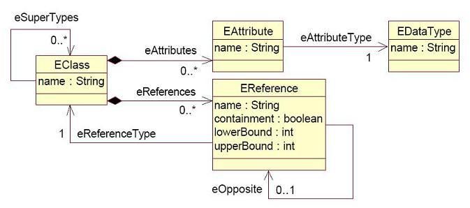
332 A Flow Controller is a subtype of PE that determines the route CASes take through multiple Analytics.
333 The Flow Controller interface defines the following operations:
334 addAvailableAnalytics, which provides the Flow Controller with access to the Analytic
335 Metadata for all of the Analytics that the Flow Controller may route CASes to. This takes a map
336 from String keys to ProcessingElementMetadata objects. This may be called multiple times, if
337 new analytics are added to the system after the original call is made.
338 removeAvailableAnalytics, which takes a set of Keys and instructs the Flow Controller to
339 remove some Analytics from consideration as possible destinations.
340 setAggregateMetadata, which provides the Flow Controller with Processing Element Metadata
341 that identifies and describes the desired behavior of the entire flow of components that the
342 FlowController is managing. The most common use for this is to specify the desired outputs of
343 the aggregate, so that the Flow Controller can make decisions about which analytics need to be
344 invoked in order to produce those outputs.
345 getNextDestinations, which takes a CAS and returns one or more destinations for this CAS.
346 continueOnFailure, which can be called by the aggregate/application when a Step issued by
347 the FlowController failed. The FlowController returns true if it can continue, and can change the
348 subsequent flow in any way it chooses based on the knowledge that a failure occurred. The
349 FlowController returns false if it cannot continue.
350
351 For the full Abstract Interfaces specification, see Section 4.4.
352 3.5 Behavioral Metadata
353 The Behavioral Metadata of an analytic declaratively describes what the analytic does; for example, what
354 types of CASs it can process, what elements in a CAS it analyzes, and what sorts of effects it may have
355 on CAS contents as a result of its application.
356
357 Behavioral Metadata is designed to achieve the following goals:
uima-spec-v1.0 2 March 2009
Copyright © OASIS® 2008. All Rights Reserved. Page 14 of 99358 1. Discovery: Enable both human developers and automated processes to search a repository and
359 locate components that provide a particular function (i.e., works on certain input, produces certain
360 output)
361
362 2. Composition: Support composition either by a human developer or an automated process.
363 a. Analytics should be able to declare what they do in enough detail to assist manual
364 and/or automated processes in considering their role in an application or in the
365 composition of aggregate analytics.
366 b. Through their Behavioral Metadata, Analytics should be able to declare enough detail
367 as to enable an application or aggregate to detect ―invalid‖ compositions/workflows
368 (e.g., a workflow where it can be determined that one of the Analytic‘s preconditions
369 can never be satisfied by the preceding Analytic).
370
371 3. Efficiency: Facilitate efficient sharing of CAS content among cooperating analytics. If analytics
372 declare which elements of the CAS (e.g., views) they need to receive and which elements they do not
373 need to receive, the CAS can be filtered or split prior to sending it to target analytics, to achieve
374 transport and parallelization efficiencies respectively.
375
376 Behavioral Metadata breaks down into the following categories:
377 Analyzes: Types of objects (Sofas) that the analytic intends to produce annotations over.
378 Required Inputs: Types of objects that must be present in the CAS for the analytic to operate.
379 Optional Inputs: Types of objects that the analytic would consult if they were present in the CAS.
380 Creates: Types of objects that the analytic may create.
381 Modifies: Types of objects that the analytic may modify.
382 Deletes: Types of objects that the analytic may delete.
383
384 Note that analytics are not required to declare behavioral metadata. If an analytic does not provide
385 behavioral metadata, then an application using the analytic cannot assume anything about the operations
386 that the analytic will perform on a CAS.
387
388 For the full Behavioral Metadata specification, see Section 4.5.
389 3.6 Processing Element Metadata
390 All UIMA Processing Elements (PEs) must publish processing element metadata, which describes the
391 analytic to support discovery and composition. This section of the spec defines the structure of this
392 metadata and provides an XML schema in which PEs must publish this metadata.
393
394 The PE Metadata is subdivided into the following parts:
395
396 1. Identification Information. Identifies the PE. It includes for example a symbolic/unique name, a
397 descriptive name, vendor and version information.
398 2. Configuration Parameters. Declares the names of parameters used by the PE to affect its
399 behavior, as well as the parameters‘ default values.
400 3. Behavioral Metadata. Describes the PEs input requirements and the operations that the PE
401 may perform, as described in Section 3.5.
402 4. Type System. Defines types used by the PE and referenced from the behavioral specification.
403 5. Extensions. Allows the PE metadata to contain additional elements, the contents of which are
404 not defined by the UIMA specification. This can be used by framework implementations to
405 extend the PE metadata with additional information that may be meaningful only to that
406 framework.
407
uima-spec-v1.0 2 March 2009
Copyright © OASIS® 2008. All Rights Reserved. Page 15 of 99408 For the full Processing Element Metadata specification, see Section 4.6.
409 3.7 WSDL Service Descriptions
410 This specification element facilitates interoperability by specifying a WSDL [WSDL1] description of the
411 UIMA interfaces and a binding to a concrete SOAP interface that compliant frameworks and services
412 MUST implement.
413
414 This SOAP interface implements the Abstract Interfaces described in Section 3.4. The use of SOAP
415 facilitates standard use of web services as a CAS transport.
416
417 For the full WSDL Service Descriptions specification, see Section 4.7.
418
uima-spec-v1.0 2 March 2009
Copyright © OASIS® 2008. All Rights Reserved. Page 16 of 99419 4 Full UIMA Specification
420 4.1 The Common Analysis Structure (CAS)
421 4.1.1 Basic Structure: Objects and Slots
422 At the most basic level a CAS contains an object graph – a collection of objects that may point to or
423 cross-reference each other. Objects are defined by a set of properties which may have values. Values
424 can be primitive types like numbers or strings or can refer to other objects in the same CAS.
425
426 This approach allows UIMA to adopt general object-oriented modeling and programming standards for
427 representing and manipulating artifacts and artifact metadata.
428
429 UIMA uses the Unified Modeling Language (UML) [UML1] to represent the structure and content of a
430 CAS.
431
432 In UML an object is a data structure that has 0 or more slots. We can think of a slot as representing an
433 object‘s properties and values. Formally a Slot in UML is a (feature, value) pair. Features in UML
434 represent an object‘s properties. A slot represents an assignment of one or more values to a feature.
435 Values can be either primitives (strings or various numeric types) or references to other objects.
436
437 UML uses the notion of classes to represent the required structure of objects. Classes define the slots
438 that objects must have. We refer to a set of classes as a type system.
439 4.1.2 Relationship to Type System
440 Every object in a CAS is an instance of a class defined in a UIMA type system.
441
442 A type system defines a set of classes. A class may have multiple features. Features may either be
443 attributes or references.
444
445 All features define their type. The type of an attribute is a primitive data type. The type of a reference is a
446 class. Features also have a cardinality (defined by a lower bound and a upper bound), which define how
447 many values they may take. We sometimes refer to features with an upper bound greater than one as
448 multi-valued features.
449
450 An object has one slot for each feature defined by its class.
451
452 Slots for attributes take primitive values; slots for references take objects as values. In general a slot may
453 take multiple values; the number of allowed values is defined by the lower bound and upper bound of the
454 feature.
455
456 The metamodel describing how a CAS relates to a type system is diagrammed in Figure 1.
457
458 Note that some UIMA components may manipulate a CAS without knowledge of its type system. A
459 common example is a CAS Store, which might allow the storage and retrieval of any CAS regardless of
460 what its type system might be.
uima-spec-v1.0 2 March 2009
Copyright © OASIS® 2008. All Rights Reserved. Page 17 of 99461
Schema
Instances
(see Type System Model)
(Object Graph)
462
463 Figure 1: CAS Specification UML
464
465 4.1.3 The XMI CAS Representation
466 A UIMA CAS is represented as an XML document using the XMI (XML Metadata Interchange) standard
467 [XMI1, XMI2]. XMI is an OMG standard for expressing object graphs in XML.
468
469 XMI was chosen because it is an established standard, aligned with the object-graph representation of
470 the CAS, aligned with UML and with object-oriented programming, and supported by tooling such as the
471 Eclipse Modeling Framework [EMF1].
472 4.1.4 CAS Formal Specification
473 4.1.4.1 Structure
474 UIMA CAS XML MUST be a valid XMI document as defined by the XMI Specification [XMI1].
475
476 This implies that UIMA CAS XML MUST be a valid instance of the XML Schema for XMI, listed in
477 Appendix C.1.
478 4.1.4.2 Constraints
479 If the root element of the XML CAS contains an xsi:schemaLocation attribute, the CAS is said to be linked
480 to an Ecore Type System. The xsi:schemaLocation attribute defines a mapping from namespace URI to
uima-spec-v1.0 2 March 2009
Copyright © OASIS® 2008. All Rights Reserved. Page 18 of 99481 physical URI as defined by the XML Schema specification [XMLS1]. Each of these physical URIs MUST
482 be a valid Ecore document as defined by the XML Schema for Ecore, presented in Appendix C.2.
483
484 A CAS that is linked to an Ecore Type System MUST be valid with respect to that Ecore Type System, as
485 defined in Section 4.2.2.2.
486 4.2 The Type System Model
487 4.2.1 Ecore as the UIMA Type System Model
488 A UIMA Type System is represented using Ecore. Figure 2 shows how Ecore is used to define the
489 schema for a CAS.
490
Schema
Instances
(Object Graph)
491
492 Figure 2: Ecore defines schema for CAS
493
494 For an introduction to Ecore and an example of a UIMA Type System represented in Ecore, see Appendix
495 B.2.
496 4.2.2 Type System Model Formal Specification
497 4.2.2.1 Structure
498 UIMA Type System XML MUST be a valid Ecore/XMI document as defined by Ecore and the XMI
499 Specification [XMI1].
500
uima-spec-v1.0 2 March 2009
Copyright © OASIS® 2008. All Rights Reserved. Page 19 of 99501 This implies that UIMA Type System XML MUST be a valid instance of the XML Schema for Ecore, given
502 in Section C.2.
503 4.2.2.2 Semantics
504 A CAS is valid with respect to an Ecore type system if each object in the CAS is a valid instance of its
505 corresponding class (EClass) in the type system, as defined by XMI [XMI1], UML [UML1] and MOF
506 [MOF1].
507 4.3 Base Type System
508 The XML namespace for types defined in the UIMA base model is http://docs.oasis-
509 open.org/uima/ns/base.ecore. (With the exception of types defined as part of Ecore, listed in Section
510 4.3.1, whose namespace is defined by Ecore.).
511
512 Examples showing how the Base Type System is used in UIMA examples can be found in Appendix B.3.
513 4.3.1 Primitive Types
514 UIMA uses the following primitive types defined by Ecore, which are analogous to the Java (and Apache
515 UIMA) primitive types:
516
517 EString
518 EBoolean
519 EByte (8 bits)
520 EShort (16 bits)
521 EInt (32 bits)
522 ELong (64 bits)
523 EFloat (32 bits)
524 EDouble (64 bits)
525
526 Also Ecore defines the type EObject, which is defined as the superclass of all non-primitive types
527 (classes).
528 4.3.2 Annotation and Sofa Base Type System
529 The Annotation and Sofa Base Type System defines a standard way for Annotations to refer to regions
530 within a Subject of Analysis (Sofa). The UML for the Annotation and Sofa Base Type System is given in
531 Figure 3. The discussion in the following subjections refers to this figure.
uima-spec-v1.0 2 March 2009
Copyright © OASIS® 2008. All Rights Reserved. Page 20 of 99532
533 Figure 3: Annotation and Sofa Base Type System UML
534
535 4.3.2.1 Annotation and Sofa Reference
536 The UIMA Base Type System defines a standard object type called Annotation for representing stand-off
537 annotations. The Annotation type represents a type of object that is linked to a Subject of Analysis (Sofa).
538
539 The Sofa is the value of a slot in another object. Since a reference directly to a slot on an object (rather
540 than just an object itself) is not a concept directly supported by typical object oriented programming
541 systems or by XMI, UIMA defines a base type called LocalSofaReference for referring to Sofas from
542 annotations. UIMA also defines a RemoteSofaReference type that allows an annotation to refer to a
543 subject of analysis that is not located in the CAS.
544 4.3.2.2 References to Regions of Sofas
545 An annotation typically points to a region of the artifact data. One of UIMA‘s design goals is to be
546 independent of modality. For this reason UIMA does not constrain the data type that can function as a
547 subject of analysis and allows for different implementations of the linkage between an annotation and a
548 region of the artifact data.
549
550 The Annotation class has subclasses for each artifact modality, which define how the Annotation refers to
551 a region within the Sofa. The Standard defines subclasses for common modalities – Text and Temporal
552 (audio or video segments). Users may define other subclasses.
553
554 In TextAnnotation, beginChar and endChar refer to Unicode character offsets in the corresponding Sofa
555 string. For TemporalAnnotation, beginTime and endTime are offsets measured in seconds from the start
556 of the Sofa. Note that applications that require a different interpretation of these fields must accept the
557 standard values and handle their own internal mappings.
558
559 Annotations with discontiguous spans are not part of the Base Type System, but could be implemented
560 with a user-defined subclass of the Annotation type.
uima-spec-v1.0 2 March 2009
Copyright © OASIS® 2008. All Rights Reserved. Page 21 of 99You can also read