Operating System for Ubiquiti M Series Products Release Version: 5.6
←
→
Page content transcription
If your browser does not render page correctly, please read the page content below
Operating System for Ubiquiti® M Series Products
Release Version: 5.6
airOS® v5.6 User Guide                                                                                                                                                                    Table of Contents

                                                                                                                            Table of Contents

                 Chapter 1: Overview. . . . . . . . . . . . . . . . . . . . . . . . . . . . . . . . . . . . . . . . . . . . . . . .  1
                            Introduction. . . . . . . . . . . . . . . . . . . . . . . . . . . . . . . . . . . . . . . . . . . . . . . . . . . . . . . . . . . . . . . . . . . . . . 1
                            Supported Products. . . . . . . . . . . . . . . . . . . . . . . . . . . . . . . . . . . . . . . . . . . . . . . . . . . . . . . . . . . . . .  1
                            airOS v5.6 Network Modes. . . . . . . . . . . . . . . . . . . . . . . . . . . . . . . . . . . . . . . . . . . . . . . . . . . . . . . .  1
                            airOS v5.6 Wireless Modes. . . . . . . . . . . . . . . . . . . . . . . . . . . . . . . . . . . . . . . . . . . . . . . . . . . . . . . .  2
                            System Requirements . . . . . . . . . . . . . . . . . . . . . . . . . . . . . . . . . . . . . . . . . . . . . . . . . . . . . . . . . . . .  2
                            Getting Started. . . . . . . . . . . . . . . . . . . . . . . . . . . . . . . . . . . . . . . . . . . . . . . . . . . . . . . . . . . . . . . . . . .  2
                            M Series Product Verification . . . . . . . . . . . . . . . . . . . . . . . . . . . . . . . . . . . . . . . . . . . . . . . . . . . . .  2
                            Navigation. . . . . . . . . . . . . . . . . . . . . . . . . . . . . . . . . . . . . . . . . . . . . . . . . . . . . . . . . . . . . . . . . . . . . . .  3

                 Chapter 2: Main. . . . . . . . . . . . . . . . . . . . . . . . . . . . . . . . . . . . . . . . . . . . . . . . . . . .  5
                            Status. . . . . . . . . . . . . . . . . . . . . . . . . . . . . . . . . . . . . . . . . . . . . . . . . . . . . . . . . . . . . . . . . . . . . . . . . . . .  5
                            Monitor. . . . . . . . . . . . . . . . . . . . . . . . . . . . . . . . . . . . . . . . . . . . . . . . . . . . . . . . . . . . . . . . . . . . . . . . . .  9

                 Chapter 3: Ubiquiti Logo . . . . . . . . . . . . . . . . . . . . . . . . . . . . . . . . . . . . . . . . . .  15
                            airMAX Settings. . . . . . . . . . . . . . . . . . . . . . . . . . . . . . . . . . . . . . . . . . . . . . . . . . . . . . . . . . . . . . . . . 15
                            airSelect. . . . . . . . . . . . . . . . . . . . . . . . . . . . . . . . . . . . . . . . . . . . . . . . . . . . . . . . . . . . . . . . . . . . . . . . . 16
                            airView. . . . . . . . . . . . . . . . . . . . . . . . . . . . . . . . . . . . . . . . . . . . . . . . . . . . . . . . . . . . . . . . . . . . . . . . . . 17
                            airSync (GPS Series Only) . . . . . . . . . . . . . . . . . . . . . . . . . . . . . . . . . . . . . . . . . . . . . . . . . . . . . . . . 19

                 Chapter 4: Wireless. . . . . . . . . . . . . . . . . . . . . . . . . . . . . . . . . . . . . . . . . . . . . . . .  23
                            Basic Wireless Settings. . . . . . . . . . . . . . . . . . . . . . . . . . . . . . . . . . . . . . . . . . . . . . . . . . . . . . . . . . . 23
                            Wireless Security. . . . . . . . . . . . . . . . . . . . . . . . . . . . . . . . . . . . . . . . . . . . . . . . . . . . . . . . . . . . . . . . 27

                 Chapter 5: Network. . . . . . . . . . . . . . . . . . . . . . . . . . . . . . . . . . . . . . . . . . . . . . . .  31
                            Network Role. . . . . . . . . . . . . . . . . . . . . . . . . . . . . . . . . . . . . . . . . . . . . . . . . . . . . . . . . . . . . . . . . . . . 31
                            Configuration Mode. . . . . . . . . . . . . . . . . . . . . . . . . . . . . . . . . . . . . . . . . . . . . . . . . . . . . . . . . . . . . 32
                            Management Network Settings – Bridge Mode. . . . . . . . . . . . . . . . . . . . . . . . . . . . . . . . . . . 33
                            Management Network Settings – Router or SOHO Mode . . . . . . . . . . . . . . . . . . . . . . . . . 34
                            WAN Network Settings . . . . . . . . . . . . . . . . . . . . . . . . . . . . . . . . . . . . . . . . . . . . . . . . . . . . . . . . . . 34
                            LAN Network Settings. . . . . . . . . . . . . . . . . . . . . . . . . . . . . . . . . . . . . . . . . . . . . . . . . . . . . . . . . . . 38
                            DHCP Address Reservation . . . . . . . . . . . . . . . . . . . . . . . . . . . . . . . . . . . . . . . . . . . . . . . . . . . . . . 40
                            Port Forwarding. . . . . . . . . . . . . . . . . . . . . . . . . . . . . . . . . . . . . . . . . . . . . . . . . . . . . . . . . . . . . . . . . 40
                            Multicast Routing Settings. . . . . . . . . . . . . . . . . . . . . . . . . . . . . . . . . . . . . . . . . . . . . . . . . . . . . . . 40
                            Interfaces . . . . . . . . . . . . . . . . . . . . . . . . . . . . . . . . . . . . . . . . . . . . . . . . . . . . . . . . . . . . . . . . . . . . . . . 41
                            IP Aliases. . . . . . . . . . . . . . . . . . . . . . . . . . . . . . . . . . . . . . . . . . . . . . . . . . . . . . . . . . . . . . . . . . . . . . . . 41
                            VLAN Network. . . . . . . . . . . . . . . . . . . . . . . . . . . . . . . . . . . . . . . . . . . . . . . . . . . . . . . . . . . . . . . . . . .41
                            Bridge Network . . . . . . . . . . . . . . . . . . . . . . . . . . . . . . . . . . . . . . . . . . . . . . . . . . . . . . . . . . . . . . . . . 42
                            Firewall . . . . . . . . . . . . . . . . . . . . . . . . . . . . . . . . . . . . . . . . . . . . . . . . . . . . . . . . . . . . . . . . . . . . . . . . . 42
                            IPv6 Firewall. . . . . . . . . . . . . . . . . . . . . . . . . . . . . . . . . . . . . . . . . . . . . . . . . . . . . . . . . . . . . . . . . . . . . 43
                            Static Routes. . . . . . . . . . . . . . . . . . . . . . . . . . . . . . . . . . . . . . . . . . . . . . . . . . . . . . . . . . . . . . . . . . . . 43
                            IPv6 Static Routes . . . . . . . . . . . . . . . . . . . . . . . . . . . . . . . . . . . . . . . . . . . . . . . . . . . . . . . . . . . . . . . 44
                            Traffic Shaping. . . . . . . . . . . . . . . . . . . . . . . . . . . . . . . . . . . . . . . . . . . . . . . . . . . . . . . . . . . . . . . . . . 44
Ubiquiti Networks, Inc.                                                                                                                                                                                   i
Table of Contents                                                                                                                                                              airOS® v5.6 User Guide

                Chapter 6: Advanced . . . . . . . . . . . . . . . . . . . . . . . . . . . . . . . . . . . . . . . . . . . . . .  45
                           Advanced Wireless Settings. . . . . . . . . . . . . . . . . . . . . . . . . . . . . . . . . . . . . . . . . . . . . . . . . . . . . . 45
                           Advanced Ethernet Settings. . . . . . . . . . . . . . . . . . . . . . . . . . . . . . . . . . . . . . . . . . . . . . . . . . . . . 46
                           Signal LED Thresholds. . . . . . . . . . . . . . . . . . . . . . . . . . . . . . . . . . . . . . . . . . . . . . . . . . . . . . . . . . . 47

                Chapter 7: Services . . . . . . . . . . . . . . . . . . . . . . . . . . . . . . . . . . . . . . . . . . . . . . .  49
                           Ping Watchdog. . . . . . . . . . . . . . . . . . . . . . . . . . . . . . . . . . . . . . . . . . . . . . . . . . . . . . . . . . . . . . . . . . 49
                           SNMP Agent. . . . . . . . . . . . . . . . . . . . . . . . . . . . . . . . . . . . . . . . . . . . . . . . . . . . . . . . . . . . . . . . . . . . .50
                           Telnet Server. . . . . . . . . . . . . . . . . . . . . . . . . . . . . . . . . . . . . . . . . . . . . . . . . . . . . . . . . . . . . . . . . . . . 51
                           NTP Client. . . . . . . . . . . . . . . . . . . . . . . . . . . . . . . . . . . . . . . . . . . . . . . . . . . . . . . . . . . . . . . . . . . . . . . 51
                           Dynamic DNS . . . . . . . . . . . . . . . . . . . . . . . . . . . . . . . . . . . . . . . . . . . . . . . . . . . . . . . . . . . . . . . . . . . 51
                           System Log. . . . . . . . . . . . . . . . . . . . . . . . . . . . . . . . . . . . . . . . . . . . . . . . . . . . . . . . . . . . . . . . . . . . . . 52
                           Device Discovery. . . . . . . . . . . . . . . . . . . . . . . . . . . . . . . . . . . . . . . . . . . . . . . . . . . . . . . . . . . . . . . . 52

                Chapter 8: System. . . . . . . . . . . . . . . . . . . . . . . . . . . . . . . . . . . . . . . . . . . . . . . . .  53
                           Firmware Update. . . . . . . . . . . . . . . . . . . . . . . . . . . . . . . . . . . . . . . . . . . . . . . . . . . . . . . . . . . . . . . . 53
                           Device . . . . . . . . . . . . . . . . . . . . . . . . . . . . . . . . . . . . . . . . . . . . . . . . . . . . . . . . . . . . . . . . . . . . . . . . . . 54
                           Date Settings. . . . . . . . . . . . . . . . . . . . . . . . . . . . . . . . . . . . . . . . . . . . . . . . . . . . . . . . . . . . . . . . . . . . 54
                           System Accounts. . . . . . . . . . . . . . . . . . . . . . . . . . . . . . . . . . . . . . . . . . . . . . . . . . . . . . . . . . . . . . . . 54
                           Miscellaneous. . . . . . . . . . . . . . . . . . . . . . . . . . . . . . . . . . . . . . . . . . . . . . . . . . . . . . . . . . . . . . . . . . . 55
                           Location . . . . . . . . . . . . . . . . . . . . . . . . . . . . . . . . . . . . . . . . . . . . . . . . . . . . . . . . . . . . . . . . . . . . . . . . 55
                           Device Maintenance. . . . . . . . . . . . . . . . . . . . . . . . . . . . . . . . . . . . . . . . . . . . . . . . . . . . . . . . . . . . . 55
                           Configuration Management. . . . . . . . . . . . . . . . . . . . . . . . . . . . . . . . . . . . . . . . . . . . . . . . . . . . . 55

                Chapter 9: Tools. . . . . . . . . . . . . . . . . . . . . . . . . . . . . . . . . . . . . . . . . . . . . . . . . . .  57
                           Align Antenna. . . . . . . . . . . . . . . . . . . . . . . . . . . . . . . . . . . . . . . . . . . . . . . . . . . . . . . . . . . . . . . . . . . 57
                           Site Survey. . . . . . . . . . . . . . . . . . . . . . . . . . . . . . . . . . . . . . . . . . . . . . . . . . . . . . . . . . . . . . . . . . . . . . 57
                           Discovery . . . . . . . . . . . . . . . . . . . . . . . . . . . . . . . . . . . . . . . . . . . . . . . . . . . . . . . . . . . . . . . . . . . . . . . 58
                           Ping. . . . . . . . . . . . . . . . . . . . . . . . . . . . . . . . . . . . . . . . . . . . . . . . . . . . . . . . . . . . . . . . . . . . . . . . . . . . . 58
                           Traceroute . . . . . . . . . . . . . . . . . . . . . . . . . . . . . . . . . . . . . . . . . . . . . . . . . . . . . . . . . . . . . . . . . . . . . . 59
                           Speed Test . . . . . . . . . . . . . . . . . . . . . . . . . . . . . . . . . . . . . . . . . . . . . . . . . . . . . . . . . . . . . . . . . . . . . . 59
                           airView. . . . . . . . . . . . . . . . . . . . . . . . . . . . . . . . . . . . . . . . . . . . . . . . . . . . . . . . . . . . . . . . . . . . . . . . . . 60

                Appendix A: Contact Information. . . . . . . . . . . . . . . . . . . . . . . . . . . . . . . . . .  63
                           Ubiquiti Networks Support. . . . . . . . . . . . . . . . . . . . . . . . . . . . . . . . . . . . . . . . . . . . . . . . . . . . . . 63

ii                                                                                                                                                                             Ubiquiti Networks, Inc.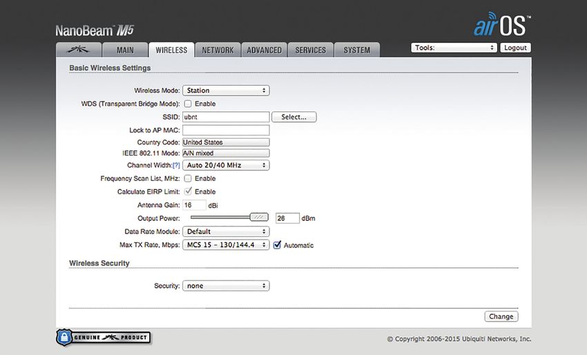
airOS® v5.6 User Guide                                                                              Chapter 1: Overview

Chapter 1: Overview                                           Supported Products
                                                              airOS v5.6 supports the M Series product versions,
Introduction                                                  including the following:
Welcome to airOS® v5.6 – the latest evolution of the airOS    • airRouter™
Configuration Interface by Ubiquiti Networks. airOS v5.6      • Rocket™M
provides numerous updates, including:                         • Rocket™M GPS
• Private SNMP MIB                                            • Rocket™M Titanium
• IPv6 Support                                                • NanoBeam®M
• QoS for VLANs                                               • NanoBridge®M
• Password Length increased to More than 8 Symbols            • NanoStation®locoM/NanoStationM
• TCP Support for Remote System Logging                       • Bullet™M
• WPA-AES/WPA2-AES Security Only (WEP optional for            • Bullet™M Titanium
  AP‑Repeater mode)
                                                              • PicoStation®M
• 5 MHz Increments Available for Frequency Selection
  When 5 GHz Devices Operate in airMAX® Mode (instead         • PowerBeam™M
  of channel shifting)                                        • PowerBridge®M
airOS is an advanced operating system capable of              • airGrid®M
powerful wireless and routing features, built upon a          • WispStation™M
simple and intuitive user interface foundation.
                                                              • airGateway™
This User Guide describes the airOS operating system
                                                              For more information, visit: www.ubnt.com
version 5.6, which is integrated into all M Series products
provided by Ubiquiti Networks.                                airOS v5.6 Network Modes
      Note: For compatibility, legacy or 802.11 a/b/g         airOS supports the following network modes:
      devices should use legacy firmware with airMAX
                                                              • Transparent Layer 2 Bridge
      support (such as airOS firmware v4.0). Legacy
      clients can only work as airMAX clients with the M      • Router
      Series device acting as an airMAX AP.                   • SOHO Router

Ubiquiti Networks, Inc.                                                                                               1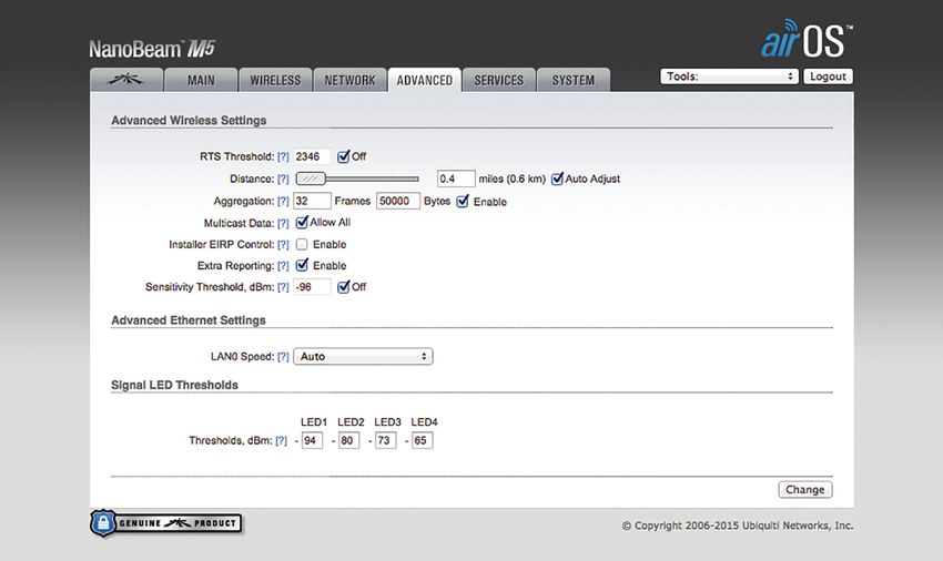
Chapter 1: Overview                                                                                 airOS® v5.6 User Guide

airOS v5.6 Wireless Modes                                     4. Upon subsequent login, the standard login screen
                                                                 appears. Enter ubnt in the Username and Password
airOS supports the following wireless modes:                     fields, and click Login.
• Access Point
• Station / Client
• AP-Repeater

System Requirements
• Microsoft Windows 7/8, Linux, or Mac OS X
• Java Runtime Environment 1.6 (or above)
• Web Browser: Mozilla Firefox, Apple Safari, Google
  Chrome, or Microsoft Internet Explorer 8 (or above)

Getting Started
                                                                    Note: To enhance security, we recommend that
To access the airOS Configuration Interface, perform the
                                                                    you change the default login in System > System
following steps:
                                                                    Accounts. For details, go to “System Accounts” on
1. Configure the Ethernet adapter on your computer                  page 54.
   with a static IP address on the 192.168.1.x subnet (for
   example, IP address: 192.168.1.100 and subnet mask:        M Series Product Verification
   255.255.255.0).                                            Starting with M series product models manufactured in
2. Launch your web browser. Enter https:// and the            2012, the airOS Configuration Interface (v5.5.2 or later) will
   default IP address of your device in the address field.    verify whether a product is genuine or counterfeit.
   Press Enter (PC) or Return (Mac).
                                                              Prior to 2012
    Device           Default IP Address
                                                              For M series product models manufactured prior to 2012,
    airRouter        192.168.1.1                              airOS will NOT display any logo in the lower left corner of
    Other Devices    192.168.1.20                             the screen.
                                                              Starting in 2012
          Note: HTTPS is the default protocol starting with
                                                              For new M series product models introduced in 2012 or
          airOS v5.5.4.
                                                              later, airOS will display a Genuine Product logo in the
    For example, enter 192.168.1.20 to access the Rocket.     lower left corner of the screen.
                                                              New production versions of existing M series product
                                                              models began using the Genuine Product logo in 2012.
                                                              (Not all M series product models manufactured in 2012
                                                              will display a Genuine Product logo.)
3. Upon initial login, the Terms of Use appear on the login
   screen. Enter ubnt in the Username and Password fields,
   and select the appropriate choices from the Country
   and Language drop-down lists. Check the box next to
   I agree to these terms of use, and click Login.
                                                              For any M series product that is not an official Ubiquiti
                                                              product, airOS will display a counterfeit warning. Please
                                                              contact Ubiquiti at support@ubnt.com regarding
                                                              this product.

                                                                    Note: If neither the Genuine Product logo nor
                                                                    counterfeit warning appears, the device was
                                                                    manufactured prior to the genuine product
                                                                    verification process and is probably genuine.
                                                                    If you have any questions, please email
                                                                    support@ubnt.com.

2                                                                                                   Ubiquiti Networks, Inc.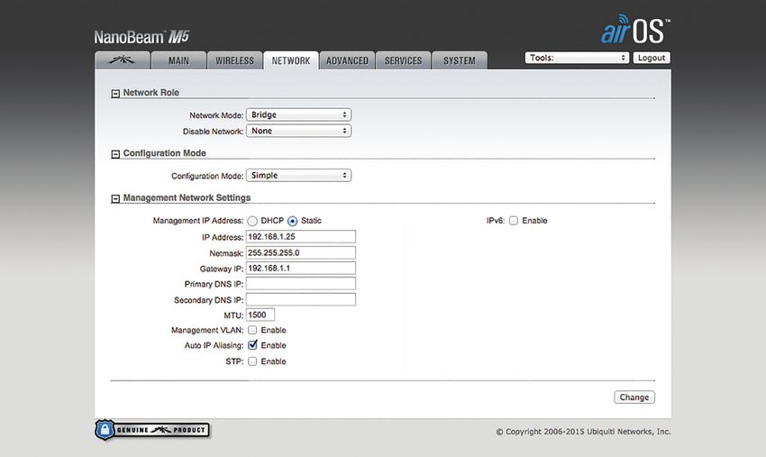
airOS® v5.6 User Guide                                         Chapter 1: Overview

Navigation
The airOS Configuration Interface contains seven main
pages, each of which provides a web-based management
page to configure a specific aspect of the Ubiquiti device:
• Ubiquiti Logo The “Ubiquiti Logo” on page 15
  controls Ubiquiti’s proprietary technologies, such as
  airMAX, airView, airSelect, and airSync (GPS Series
  devices only).
        Note: By default, indoor products, such as the
        airRouter, do not display the Ubiquiti logo page.
        However, you can enable the Ubiquiti logo
        page through System > Miscellaneous > airMAX
        Technology Features. For more information, see
        “Miscellaneous” on page 55.
• Main The “Main” on page 5 displays device status,
  statistics, and network monitoring links.
• Wireless The “Wireless” on page 23 configures
  basic wireless settings, including the wireless mode,
  Service Set Identifier (SSID), 802.11 mode, channel and
  frequency, output power, data rate module, and wireless
  security.
• Network The “Network” on page 31 configures the
  network operating mode; Internet Protocol (IP) settings;
  IP aliases; VLANs; packet filtering, bridging, and routing
  routines; and traffic shaping.
• Advanced The “Advanced” on page 45 provides
  more precise wireless interface controls, including
  advanced wireless settings, advanced Ethernet settings,
  and signal LED thresholds.
• Services The “Services” on page 49 configures
  system management services: Ping Watchdog, Simple
  Network Management Protocol (SNMP), servers (web,
  SSH, Telnet), Network Time Protocol (NTP) client,
  Dynamic Domain Name System (DDNS) client, system
  log, and device discovery.
• System The “System” on page 53 controls
  system maintenance routines, administrator account
  management, location management, device
  customization, firmware update, and configuration
  backup. You can also change the language of the web
  management interface.
Each page also contains network administration and
monitoring tools:
• “Align Antenna” on page 57
• “Site Survey” on page 57
• “Discovery” on page 58
• “Ping” on page 58
• “Traceroute” on page 59
• “Speed Test” on page 59
• “airView” on page 60

Ubiquiti Networks, Inc.                                                          3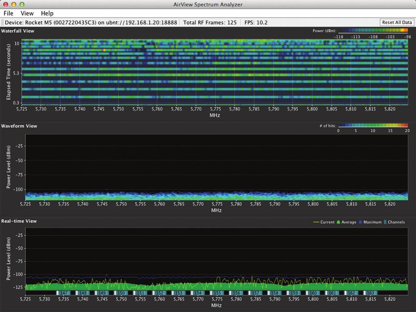
Chapter 1: Overview   airOS® v5.6 User Guide

4                     Ubiquiti Networks, Inc.
airOS® v5.6 User Guide                                                                               Chapter 2: Main

Chapter 2: Main                                          Device Name Displays the customizable name or
                                                         identifier of the device. The Device Name (also known
The Main page displays a summary of the link status      as host name) is displayed in registration screens and
information, current values of the basic configuration   discovery tools.
settings (depending on the operating mode), network      Network Mode Displays the network operating mode.
settings and information, and traffic statistics.        airOS supports three modes: Bridge, Router, and SOHO
                                                         Router. The default setting is device-specific. Configure the
Status                                                   Network Mode on the Network page (for details, refer to
                                                         ”Network Role” on page 31).

Ubiquiti Networks, Inc.                                                                                              5
Chapter 2: Main                                                                                      airOS® v5.6 User Guide

Wireless Mode Displays the operating mode of the                Channel/Frequency Displays the channel number and
radio interface. airOS supports three operating modes:          corresponding operating frequency. The device uses
Station, Access Point, and AP‑Repeater. The default setting     the channel and radio frequency specified to transmit
is device‑specific. Configure the Wireless Mode on the          and receive data. Valid channel and frequency ranges
Wireless page. If Station or Access Point mode is enabled,      will vary depending on local country regulations. If the
then you can also select WDS (Wireless Distribution             Channel/Frequency is labeled as “DFS”, then the device is
System) as needed.                                              using a DFS (Dynamic Frequency Selection) channel. (DFS
airOS also supports airView (spectrum analyzer) mode, a         channels/frequencies are not available on all devices.)
temporary mode that terminates all wireless connections.        Channel Width This is the spectral width of the radio
To select airView mode, click Tools > airView or click          channel used by the device. airOS v5.6 supports 3, 5, 7,
Launch airView on the Ubiquiti Logo page. When the              8, 10, 14, 20, 25, 28, 30, and 40 MHz; however, available
device is running in airView mode, all wireless connections     channel widths are device-specific. In Station mode, Auto
will be terminated during the airView session. Close the        20/40 MHz is the value by default.
airView window to return to the previous wireless mode.         Frequency Band Displays the actual operating frequency
Any M Series device may operate in only one of these            range of the device. This is based on the selected
modes at a time. For example, if the device is running          frequency, channel width, and extension channel on the
in Access Point mode, it cannot simultaneously run in           Wireless page.
Station mode.
                                                                Distance Displays the current distance between devices
                                                                in kilometers and miles for Acknowledgement (ACK)
                                                                frames. Changing the distance value will change the
                                                                ACK (Acknowledgement) timeout accordingly. The ACK
                                                                timeout specifies how long the device should wait for
                                                                an acknowledgement from a partner device confirming
                                                                frame reception before it concludes that there has been
                                                                an error and resends the frame. You can adjust the
                                                                Distance value; for more information, see “Distance” on
                                                                page 46).
                                                                TX/RX Chains Displays the number of independent
                                                                spatial data streams the device is transmitting (TX)
SSID Displays the wireless network name (SSID). The             and receiving (RX) simultaneously within one spectral
wireless network name depends upon the wireless mode            channel of bandwidth. This ability is specific to 802.11n
selected:                                                       devices that rely on Multiple-Input Multiple-Output
                                                                (MIMO) technology. Multiple chains increase data transfer
    • In Station mode, this displays the SSID of the AP the     performance significantly. The number of chains Ubiquiti
      device is associated with.                                devices use is hardware-specific because every TX/RX
    • In Access Point mode, this displays the SSID configured   chain requires a separate antenna.
      on the device using the Wireless page.                    Antenna (Only applicable to devices with antenna
Security Displays the wireless security method being            options.) The antenna type (Internal, External, or External +
used on the device. If None is displayed, then wireless         Internal) is displayed. For more information, see “Antenna”
security has been disabled, although you can still use          on page 26.
RADIUS MAC authentication.                                      WLAN0 MAC Displays the MAC address of the device as
Version Displays the airOS software version.                    seen on the wireless network.
Uptime This is the total time the device has been running       LAN0 MAC Displays the MAC address of the device as
since the latest reboot (when the device was powered up)        seen on the LAN.
or software upgrade. The time is displayed in days, hours,      LAN1 MAC Displays the MAC address of the device
minutes, and seconds.                                           as seen on the WAN interface. This is the device’s MAC
Date Displays the current system date and time, which           address as seen over the Internet.
is retrieved from the Internet using NTP (Network Time          LAN0/LAN1 Displays the Ethernet port speed and duplex
Protocol). The NTP Client is disabled by default on the         mode, such as 1000Mbps-Full or 100Mbps-Full. This can
Services page. The device doesn’t have an internal clock,       indicate that a cable is not plugged into a device or there
and the date and time may be inaccurate if the NTP Client       is no active Ethernet connection.
is disabled or the device isn’t connected to the Internet.
                                                                AP MAC In Access Point or AP‑Repeater mode, this
                                                                displays the MAC address of the device. In Station mode,
                                                                this displays the MAC address of the AP the device is
                                                                associated with.

6                                                                                                    Ubiquiti Networks, Inc.
airOS® v5.6 User Guide Chapter 2: Main
Signal Strength (Available in Station mode only.) Note: For compatibility, legacy or 802.11 a/b/g
Displays the received wireless signal level (client-side). devices should use legacy firmware with airMAX
The represented value coincides with the graphical bar. support (such as airOS firmware v4.0). Legacy
Use the antenna alignment tool to adjust the device clients can only work as airMAX clients with the M
antenna to get a better link with the wireless device. The Series device acting as an airMAX AP.
antenna of the wireless client has to be adjusted to get airMAX Priority Available if airMAX is enabled in Station
the maximum signal strength. Signal Strength is measured mode only. Indicates the airMAX Priority set on the Ubiquiti
in dBm (the decibels referenced to 1 milliwatt). The logo page. By default the AP gives all active clients
conversion is defined as dBm=10log10(P/1mW). So, 0 dBm the same amount of time. However, if the clients are
would be 1 mW and -72 dBm would be 0.0000006 mW. configured with different priorities, the AP will give clients
A signal strength of -80 dBm or better (-50 to -70 dBm) is more or less time, depending on the priority.
recommended for stable links.
airMAX Quality Available if airMAX is enabled. airMAX
Quality (AMQ) is based on the number of retries and the
quality of the physical link. If this value is low, you may
have interference and need to change frequencies. If AMQ
is above 80% and you do not notice any other issues, then
you do not need to make any changes.
airMAX Capacity Available if airMAX is enabled. airMAX
Capacity (AMC) is based on airtime efficiency. For example,
if you have one client with a low data rate or you are using
a 1x1 device (such as Bullet or airGrid) alongside other
clients that are 2x2, then it will use up more airtime (slots)
for the same amount of data, reducing time (or capacity)
Chain or Horizontal/Vertical or External/Internal for other clients. The lower the AMC, the less efficient the
(Vertical) (Available in Station mode only.) Displays AP is. If you only have one client, this may not matter, but
the wireless signal level (in dBm) of each signal. Devices when you have many clients (for example, more than 30),
with fixed antennas display Horizontal/Vertical instead of then AMC becomes very important, and you want it to be
Chain. When chains are displayed, the number of chains is as high as possible.
device-specific. If you are looking at the client, AMC shows the theoretical
The NanoStationM900 loco displays External/Internal capacity of that client, based on current TX/RX rates and
(Vertical) if the Antenna option on the Wireless page is quality. AMC is a percentage based on what the maximum
set to External + Internal (2x2). For more information, see performance would be if the link were perfect. Clients
“Antenna” on page 26. with poor airtime efficiency can negatively affect other
clients by taking up more airtime while transmitting at
Connections (Available in Access Point or AP‑Repeater lower speeds. For example, client A is at MCS 12 (78 Mbps)
mode only.) Displays the number of wireless devices because of low signal. The client could theoretically
connected to the device. do MCS 15 (130 Mbps), so AMC is based on the ratio
Noise Floor Displays the current value (in dBm) of the of current rate/maximum rate (78 Mbps divided by
environmental noise (from interference) the receiver hears 130 Mbps), which is 60%. In a similar fashion, a 1x1 device
on the operating frequency. airOS considers the Noise will always have a maximum AMC of 50%, because it
Floor while evaluating the signal quality (Signal-to-Noise provides half the performance of a 2x2 device.
Ratio SNR, RSSI). The value mean depends on the signal If you are looking at the AP, then AMQ and AMC are
strength above the Noise Floor. averages of all clients’ values. If you want to discover
Transmit CCQ This index evaluates the wireless Client what is lowering your values on heavily populated APs,
Connection Quality (CCQ). The level is based on a single out the weak clients. You can either use airControl™
percentage value for which 100% corresponds to a perfect (recommended), or you can go to each client individually.
link state. Try to upgrade to a higher-gain antenna (to allow a better
TX Rate/RX Rate (Available in Station mode only.) data rate), or upgrade to a 2x2 device if you are using a
Displays the current 802.11 data transmission (TX) and 1x1 device.
data reception (RX) rates. airSelect (Available in Access Point or AP‑Repeater mode
airMAX Indicates the airMAX status. If airMAX is enabled, only.) Indicates the airSelect status. If airSelect is enabled,
the device will only accept airMAX clients. airMAX also airSync is not available. Access airSelect setup through
features advanced QoS autodetection settings. For more Ubiquiti Logo > airSelect.
information, refer to “airMAX Settings” on page 15. Hop Interval Available if airSelect is enabled. The duration
(in milliseconds) that the AP will stay on one frequency
before moving to the next.
Ubiquiti Networks, Inc. 7Chapter 2: Main airOS® v5.6 User Guide
airSync (GPS Series Only) Indicates the airSync status. If
airSync is enabled, airSelect is not available, and the device
in Master mode reports the number of airSync-enabled
devices in Slave mode. Access airSync setup through
Ubiquiti Logo > airSync.
GPS Signal Quality (GPS Series Only) Displays GPS
signal quality as a percentage value on a scale of 0-100%.
Latitude/Longitude (GPS Series Only) Based on
GPS tracking, reports the device’s current latitude and
longitude. Clicking the link opens the reported latitude
and longitude in a browser using Google Maps™
(http://maps.google.com). airMAX Gateway Displayed if your airMAX device is a CPE
Altitude (GPS Series Only) Based on GPS tracking, connected to an airMAX Gateway. You can click Connected
reports the device’s current altitude above sea level. (Click to manage) to remotely provision the airGateway.
Custom Scripts Displayed if custom scripts are present The CPE must be running airOS v5.5.8 or higher to be
on the device. If custom scripts are running, then the Main compatible for pairing. Follow these instructions on
page displays the status of this option as “Detected” and the CPE:
the Manage button. Click Manage and the Custom Scripts 1. On the Wireless page, configure Wireless Mode: Station.
Management screen appears: 2. On the Network page, configure Network Mode: Router.
3. For the Configuration Mode, select Advanced.
4. View the Bridge Network section. Remove all ports and
then remove the Bridge. (Refer to “WAN Network
Settings” on page 34 for more information.)
5. In the LAN Network Settings section, add LAN0 and
configure the rest of the settings. (Do not use the
• Enabled Select to run the custom script. 192.168.1.x subnet on the CPE’s LAN0 setup.)
• Script Name Displays a descriptive name. 6. Click Change.
• Download Script Click to download the custom script. To pair the airGateway, follow these instructions:
• Remove Script Click to delete the custom script. 1. Reset the airGateway to its factory defaults. (If the
• Save To save changes, click Save. devices are already connected, then reboot both
devices.)
Note: The device will be automatically restarted
when changes are saved. 2. Follow the instructions in the airGateway Quick Start
Guide (available at downloads.ubnt.com) to connect
• Close To close this screen, click Close.
the airGateway to the CPE.
3. Access the Configuration Interface of the CPE.
4. On the Main page, click Connected (Click to manage)
to remotely access the airGateway.
8 Ubiquiti Networks, Inc.airOS® v5.6 User Guide Chapter 2: Main
Monitor Latency (Available if the Auto Adjust setting is enabled
through Advanced Wireless > Advanced Wireless Settings.)
There are various monitoring tools accessible via the links Displays the latency value, in milliseconds, for wireless
on the Main page. The default is Throughput, which is frames.
displayed when you first open the Main page.
Distance (Available if the Auto Adjust setting is enabled
Throughput through Advanced Wireless > Advanced Wireless Settings.)
Displays the current distance between devices in miles for
Acknowledgement (ACK) frames. Click miles to display
the distance in km. Then you can click km to display the
distance in miles.
With Auto Adjust enabled, the auto‑acknowledgement
timeout algorithm of the device dynamically optimizes
the frame acknowledgement timeout value without user
intervention.
Throughput displays the current data traffic on the LAN TX/RX, Mbps The TX value represents the data rates, in
and WLAN in both graphical and numerical form. The Mbps, of the last transmitted packets, and the RX value
chart scale and throughput dimension (Bps, Kbps, Mbps) represents the data rates, in Mbps, of the last received
change dynamically depending on the mean throughput packets.
value. The statistics are updated automatically. CCQ, % This index evaluates the wireless Client
Refresh If there is a delay in the automatic update, click Connection Quality (CCQ). The level is a percentage value
Refresh to manually update the statistics. for which 100% corresponds to a perfect link state.
Connection Time Displays the station’s association time
Stations to the AP. The time is expressed in days, hours, minutes,
(Available in Access Point or AP‑Repeater mode only.) and seconds.
This selection lists the stations that are connected to the
Last IP Displays the station’s last IP address. Click the IP
device.
address to access the device.
Action Displays available options for this station. For
example, click kick to drop the connection to this station.
Refresh To update the information, click Refresh.
Station Information
The following statistics for each station are displayed in Detailed information is displayed when you click a specific
the station statistics window: MAC address:
Station MAC Displays the MAC address of the station.
This is a clickable link that will display additional station
information.
Device Name Displays the station’s host name. The
device name can be changed on the System page.
TX Signal, dBm The TX Signal, dBm Combined value
represents the last transmitted wireless signal level. Click
Combined to display the separate Chain 0 and Chain 1
signal values. Then you can click Chain0/Chain1 to display
the combined signal value. (Devices with fixed antennas
display Horizontal/Vertical instead of Chain. When chains
are displayed, the number of chains is device-specific.)
RX Signal, dBm The RX Signal, dBm Combined value
represents the last received wireless signal level. Click
Combined to display the separate Chain 0 and Chain 1
signal values. Then you can click Chain0/Chain1 to display
• Station Displays the MAC address of the station.
the combined signal value. (Devices with fixed antennas
display Horizontal/Vertical instead of Chain. When chains • Device Name Displays the host name of the station.
are displayed, the number of chains is device-specific.) • Product Displays the product name of the device.
Noise, dBm The Noise value represents the noise level. • Firmware Displays the firmware version of airOS.
• Connection Time Displays the amount of time the
station has been connected to the device. The time is
expressed in days, hours, minutes, and seconds.
Ubiquiti Networks, Inc. 9Chapter 2: Main airOS® v5.6 User Guide
• RX Signal The value represents, in dBm, the last • Negotiated Rate/Last Signal, dBm Values represent
received wireless signal level. the received wireless signal level along with the data
• TX Signal The value represents, in dBm, the last rates of recently received packets. N/A is displayed as the
transmitted wireless signal level. Last Signal if no packets were received on that specific
data rate.
• Noise Floor Displays the current value (in dBm) of the
environmental noise (from interference) the receiver • Kick To drop the connection to the station, click Kick.
hears on the operating frequency. airOS considers • Refresh To update the information, click Refresh.
the Noise Floor while evaluating the signal quality • Close To close the Station Info window, click Close.
(Signal‑to‑Noise Ratio SNR, RSSI). The value mean
depends on the signal strength above the Noise Floor. AP Information
• Distance (Available if the Auto Adjust setting is (Available in Station mode only.) This selection lists the
enabled through Advanced Wireless > Advanced Wireless connection statistics of the AP associated with the device.
Settings.) Displays the current distance between
devices in kilometers and miles for Acknowledgement
(ACK) frames. With Auto Adjust enabled, the device’s
auto‑acknowledgement timeout algorithm dynamically
optimizes the frame acknowledgement timeout value
without user intervention.
• CCQ The value represents the quality of the connection
to the AP. This index evaluates the wireless Client
Connection Quality (CCQ). The level is a percentage
value for which 100% corresponds to a perfect link state.
• TX Power Displays the transmit power (in dBm) of the
station.
• airMAX Priority The airMAX Priority of this station’s
traffic in comparison to the other stations.
• airMAX Quality The airMAX Quality level is based on
a percentage value for which 100% corresponds to a
perfect link state.
• airMAX Capacity This is an index of the maximum data
Access Point Displays the MAC address of the AP.
rate the link is operating at. A lower capacity number
indicates a unit that is slowing down the system. Device Name Displays the host name of the AP.
• Last IP Displays the station’s last IP address. Click the IP Product Displays the product name of the device.
address to access the device. Firmware Displays the firmware version of airOS.
• TX/RX Rate Displays the actual 802.11n data rate, Connection Time Displays the amount of time the device
which is restricted by the wireless link modulation/ has been connected to the AP. The time is expressed in
mode/protocol used, in Mbps, of the last transmitted days, hours, minutes, and seconds.
and received packets.
RX Signal The value represents, in dBm, the last received
• TX/RX Bit Rate Displays the actual bit rate, in bps, wireless signal level.
of the user data/traffic load/data stream/throughput
TX Signal The value represents, in dBm, the last
(the number of bits transmitted and received from the
transmitted wireless signal level.
station during the last second).
Noise Floor Displays the current value (in dBm) of the
• TX/RX Packets Displays the total number of packets
environmental noise (from interference) the receiver hears
transmitted and received from the station during the
on the operating frequency. airOS considers the Noise
connection uptime.
Floor while evaluating the signal quality (Signal-to-Noise
• TX/RX Packet Rate, pps Displays the mean value of the Ratio SNR, RSSI). The value mean depends on the signal
transmitted and received packet rates. strength above the Noise Floor.
• Bytes Transmitted Displays the total amount of data Distance (Available if the Auto Adjust setting is enabled
(in bytes) transmitted during the connection and a user- through Advanced Wireless > Advanced Wireless Settings.)
friendly equivalent in parentheses. Example: Displays the current distance between devices in miles for
Bytes Transmitted: 6329846 (6.33 MBytes) Acknowledgement (ACK) frames. Click miles to display
the distance in km. Then you can click km to display the
• Bytes Received Displays the total amount of data
distance in miles.
(in bytes) received during the connection and a user-
friendly equivalent in parentheses.
10 Ubiquiti Networks, Inc.airOS® v5.6 User Guide Chapter 2: Main
CCQ The value represents the quality of the connection to IP Address Displays the IP addresses of the interface.
the AP. This index evaluates the wireless Client Connection
Note: There are typically two addresses per
Quality (CCQ). The level is a percentage value for which
management interface in case IPv6 is enabled.
100% corresponds to a perfect link state.
Example:
Last IP Displays the device’s last IP address. Click the IP
192.168.1.20 FE80::227:22FF:FEEC:E770/64
address to access the device.
RX Bytes Displays the total amount of data (in bytes)
TX/RX Rate Displays the actual 802.11n data rate, which
received by the interface.
is restricted by the wireless link modulation/mode/
protocol used, in Mbps, of the last transmitted and RX Errors Displays the number of receive errors.
received packets. TX Bytes Displays the total amount of data (in bytes)
TX/RX Bit Rate Displays the actual bit rate, in bps, of transmitted by the interface.
the user data/traffic load/data stream/throughput (the TX Errors Displays the number of transmit errors.
number of bits transmitted and received from the station Refresh To update the information, click Refresh.
during the last second).
TX/RX Packets Displays the total number of packets DHCP Client
transmitted and received from the station during the (Available in Router or SOHO Router mode only.) Displays
connection uptime. the device’s WAN IP address, netmask, DNS servers, and
TX/RX Packet Rate, pps Displays the mean value of the gateway while the device is operating as a DHCP client of
transmitted and received packet rates. an external DHCP server.
Bytes Transmitted Displays the total amount of data (in
bytes) transmitted during the connection and a user-
friendly equivalent in parentheses. Example:
Bytes Transmitted: 6329846 (6.33 MBytes)
Bytes Received Displays the total amount of data (in
bytes) received during the connection and a user-friendly
equivalent in parentheses.
Negotiated Rate/Last Signal, dBm Values represent the
received wireless signal level along with the data rates Interface Displays the interface that connects to the
of recently received packets. N/A is displayed as the Last WAN.
Signal if no packets were received on that specific data IP Address Displays the IP address assigned by an
rate. external DHCP server connected to the WAN interface.
Reconnect To establish the wireless link to the AP again, If an external DHCP server is not found, the IP address
click Reconnect. will use the DHCP Fallback IP defined in the WAN Network
Settings. See “WAN Network Settings” on page 34 for
Refresh To update the information, click Refresh.
additional details.
Interfaces Netmask Displays the Netmask assigned by an external
Displays the name, MAC address, MTU, IP address, and DHCP server connected to the WAN interface. If an
traffic information for the device’s interfaces. external DHCP server is not found, the IP address will use
the DHCP Fallback Netmask defined in the WAN Network
Settings. See “WAN Network Settings” on page 34 for
additional details.
Gateway Displays the gateway address assigned by an
external DHCP server connected to the WAN interface.
Primary/Secondary DNS IP Displays the DNS IP
address(es) assigned by an external DHCP server. The
Interface Displays the name of the interface.
Domain Name System (DNS) is an Internet “phone book”
MAC Address Displays the MAC address of the interface. that translates domain names to IP addresses. These fields
MTU Displays the Maximum Transmission Unit (MTU), identify the server IP addresses that the device uses for
which is the maximum frame size (in bytes) that a network translation.
interface can transmit or receive. The default is 1500. DHCP Server Displays the IP address of the external
DHCP server that assigns the WAN IP address to the
device.
Domain Displays the domain name.
Ubiquiti Networks, Inc. 11Chapter 2: Main airOS® v5.6 User Guide
Total Lease Time Shows the total time (validity) of the Interface The Bridge Table shows which bridge port
leased IP address assigned by the external DHCP server. or interface, LAN (Ethernet) or WLAN (Wireless), the
Remaining Lease Time Displays the remaining time specific network device is associated with. airOS can
of the leased IP address assigned by the external DHCP forward packets only to the specified port of the device,
server. eliminating redundant copies and transmits.
Renew To request new IP settings from the external Aging Timer Displays aging time for each address entry
DHCP server, click Renew. (in seconds). After a specific timeout, if the device has not
seen a packet coming from a listed address, it will delete
Release To release the current IP settings, click Release. that address from the Bridge Table.
Note: Releasing the DHCP client’s IP settings may Refresh To update the information, click Refresh.
terminate the management connection to the
device. Routes
Refresh To update the information, click Refresh. Lists all the entries in the system routing table.
ARP Table
Lists all the entries of the Address Resolution Protocol
(ARP) table currently recorded on the device.
ARP is used to associate each IP address to the unique
hardware MAC address of each device on the network. It
is important to have unique IP addresses for each MAC
address or else there will be ambiguous routes on the
network.
airOS examines the destination IP address of each data
packet traveling through the system and chooses the
appropriate interface to forward the packet to. The system
choice depends on static routing rules, the entries that
are registered in the system routing table. Static routes to
IP Address Displays the IP address assigned to a network specific hosts, networks, or the default gateway are set up
device. automatically according to the IP configuration of all the
airOS Configuration Interfaces.
MAC Address Displays the MAC address of the device.
Note: You can also manually add static routes (refer
Interface Displays the interface that connects to the
to “Static Routes” on page 43 for details).
device.
Refresh To update the information, click Refresh. IPv4 Routes
Destination Displays the IP address of the destination
Bridge Table network or host.
(Available in Bridge mode only.) The table displays the
Gateway Displays the IP address of the appropriate
entries in the system Bridge Table.
gateway.
Netmask Displays the netmask of the destination
network: 255.255.255.255 for a destination host or 0.0.0.0
for the default route.
Interface Displays the interface that will receive the
packets for that route.
Bridge The name of the bridge. Note: The default route is the route that is used
MAC Address The network device identified by its MAC when no other routes for the destination are found
address. in the routing table.
12 Ubiquiti Networks, Inc.airOS® v5.6 User Guide Chapter 2: Main
IPv6 Routes Port Forward
For IPv6 addresses, the airOS Configuration Interface (Available in Router or SOHO Router mode only.) Port
supports “::” (double‑colon) notation, which substitutes forwarding allows you to connect to a specific service such
“::” for a contiguous sequence of 16-bit blocks set to zero. as an FTP server or web server. Port forwarding creates a
Here is an example: 2001:db8::1 transparent tunnel through a firewall/NAT, granting access
If written out, the IPv6 address becomes: from the WAN side to the specific network service running
2001:db8:0000:0000:0000:0000:0000:0001 on the LAN side.
Note: You can also manually add static routes (refer
to “IPv6 Static Routes” on page 44 for details).
Destination Displays the IP address of the destination
network or host.
Gateway Displays the IP address of the appropriate
gateway.
Interface Displays the interface that will receive the Port Forward Rules Lists active port forward entries in
packets for that route. the PREROUTING chain of the standard iptables nat table,
while the device is operating in Router or SOHO Router
Refresh To update the information, click Refresh. mode.
Firewall Refresh To update the information, click Refresh.
When the firewall is enabled on the Network page, this Configure port forwarding rules on the Network page. See
option is available. By default, there are no firewall rules. “Traffic Shaping” on page 44 for additional details.
If the device is operating in Bridge mode, the table lists DHCP Leases
active firewall entries in the FIREWALL chain of the
standard ebtables filter table. (Available in Router or SOHO Router mode only with the
DHCP server feature enabled.) Displays the current status
If the device is operating in Router or SOHO Router mode, of the IP addresses assigned by the device’s DHCP server
the table lists active firewall entries in the FIREWALL chain to its local DHCP clients.
of the standard iptables filter table.
Firewall Rules IP and MAC level access control and
packet filtering in airOS are implemented using an
ebtables (bridging) or iptables (routing) firewall that MAC Address Displays the client’s MAC address.
protects the resources of a private network from outside
threats by preventing unauthorized access and filtering IP Address Displays the client’s IP address.
specified types of network communication. Remaining Lease Displays the remaining time of the
Refresh To update the information, click Refresh. leased IP address assigned by the DHCP server.
Configure firewall rules on the Network page. See Hostname Displays the device name of the client.
“Firewall” on page 42 or “IPv6 Firewall” on page Refresh To update the information, click Refresh.
43 for additional details.
Ubiquiti Networks, Inc. 13Chapter 2: Main airOS® v5.6 User Guide GPS Details (GPS Series Only) GPS Details (available on GPS Series devices only) displays GPS Satellite details and Signal quality. Refresh To update the information, click Refresh. Log When logging is enabled (see “System Log” on page 52 to enable logging), this option lists all registered system events. By default, logging is not enabled. Clear To delete all entries in the system log, click Clear. Refresh To update the log content, click Refresh. 14 Ubiquiti Networks, Inc.
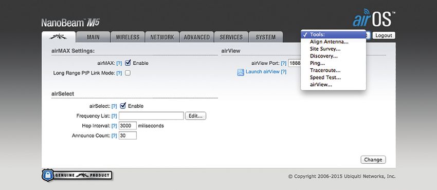
airOS® v5.6 User Guide                                                                             Chapter 3: Ubiquiti Logo

Chapter 3: Ubiquiti Logo                                      airMAX Settings
                                                              airMAX is Ubiquiti’s proprietary Time Division Multiple
The Ubiquiti logo page displays settings to enable, launch,   Access (TDMA) polling technology. airMAX improves
and change settings for Ubiquiti’s proprietary features,      overall performance in Point-to-Point (PtP) and
including:                                                    Point‑to‑MultiPoint (PtMP) installations and noisy
• airMAX® Provides superior wireless performance, more        environments because it reduces latency, increases
  clients per Access Point (AP), and lower latency under      throughput, and offers better tolerance against
  load.                                                       interference. Because of its advantages, airMAX also
• airSelect® Dynamically changes the wireless channel to      increases the maximum possible number of users that can
  avoid interference.                                         associate with an AP that uses airMAX.

• airView® Ubiquiti’s spectrum analyzer.                      airMAX assigns time slots for each device communication
                                                              to avoid the “hidden node” problem, which occurs when
• airSync™ Synchronizes transmissions by GPS Series           a node is visible from a wireless AP, but not from other
  devices to eliminate co-location transmit interference.     nodes communicating with the originating AP.
      Note: By default, indoor products, such as the          airMAX also features advanced Quality of Service (QoS)
      airRouter, do not display the Ubiquiti logo page.       autodetection settings. For airMAX to classify and
      However, you can enable the Ubiquiti logo               differentiate types of traffic when applying QoS rules,
      page through System > Miscellaneous > airMAX            the traffic must have a special value within the TOS
      Technology Features. For more information, see          (Type of Service) range and set in the IP Header DSCP
      “Miscellaneous” on page 55.                             (Differentiated Services Code Point) field. The original
Change To save or test your changes, click Change.            software or hardware device is responsible for setting this
                                                              value; airMAX will prioritize traffic only if this value is set.
A new message appears. You have three options:
                                                              There are four WME (Wireless Multimedia Enhancements)
• Apply To immediately save your changes, click Apply.
                                                              categories, which range from lowest to highest priority in
• Test To try the changes without saving them, click          this order:
  Test. To keep the changes, click Apply. If you do not
                                                              • Best Effort
  click Apply within 180 seconds (the countdown is
  displayed), the device times out and resumes its earlier    • Background
  configuration.                                              • Video
• Discard To cancel your changes, click Discard.              • Voice

Ubiquiti Networks, Inc.                                                                                                     15
Chapter 3: Ubiquiti Logo airOS® v5.6 User Guide
By default, all traffic is classified as Best Effort, so no Note: If you use Long Range PtP Link Mode, then
prioritization is applied. The categories can be defined the Auto Adjust setting on the Advanced page is
using the following values: not available.
802.1p Class of Service TOS Range DSCP Range WME Category If your device has multiple stations or clients, do not
0 – Best Effort 0x00-0x1f 0-7 Best Effort use Long Range PtP Link Mode; instead, enable the Auto
Adjust setting on the Advanced page (see “Auto Adjust”
1 – Background 0x20-0x3f 8-15 Background
on page 46 for additional details).
2 – Spare 0x40-0x5f 16-23 Background
• airMAX Priority (Available in Station mode only.) It
3 – Excellent Effort 0x60-0x7f 24-25, 28-31 Best Effort defines the number of time slots (or amount of airtime)
4 – Controlled Load 0x80-0x9f 32-39 Video assigned to each client. By default the AP gives all active
clients the same amount of time. However, if the clients
5 – Video
(airOS® v5.6 User Guide Chapter 3: Ubiquiti Logo
• airSelect Check the box to enable airSelect. When • Do NOT warn me about this in the future Check the
airSelect is enabled, the AP and all associated clients box to bypass this window in future launches of the
quickly hop between frequencies to avoid interference. airView Spectrum Analyzer.
• Frequency List Available when airSelect is enabled. • Launch airView Click Launch airView to download the
Click Edit to select the frequencies that the AP will Java Network Launch Protocol (jnlp) file and complete
use for airSelect. Available frequencies are device- the launch of airView.
dependent.
• Hop Interval Available when airSelect is enabled. The
duration (in milliseconds) that the AP will stay on one
frequency before moving to the next. The default value
is 3000 milliseconds (ms).
• Announce Count Available when airSelect is
enabled. The number of times between hops the
AP will announce the next hop information (such as
frequency) to clients. For example, if the Hop Interval
is set to 3000 ms (default), and the Announce Count is
set to 30 (default), then every 100 ms the AP will send
an announcement with upcoming hop information
to the clients. The larger the time period between the
Announce Count and Hop Interval, the higher the risk
of timing drift (hops not being synchronized), so we
recommend that you keep the defaults or configure
the AP to send an announcement every 100 ms (set
the Announce Count to 1/100th of the Hop Interval).
airView
Use the airView Spectrum Analyzer to analyze the noise
environment of the radio spectrum and intelligently select
the optimal frequency to install a PtP airMAX link.
airView options include:
Main View
Device Displays the device name, MAC (Media Access
• airView Port Defines the TCP port used by airView on Control) address, and IP address of the device running
the device. The default port is 18888. airView.
• Launch airView There are two system requirements for Total RF Frames Displays the total number of Radio
the airView Spectrum Analyzer: Frequency (RF) frames gathered since the start of the
• Your system is connected to the device via Ethernet. airView session or since the Reset All Data button was last
Launching airView will terminate all wireless clicked.
connections on the device. FPS Displays the total number of frames per second (FPS)
• Java Runtime Environment 1.6 (or above) is required gathered since the start of the airView session or since
on your client machine to use airView. the Reset All Data button was last clicked. The wider the
interval amplitude, the fewer the FPS will be gathered.
Click Launch airView to use the airView Spectrum
Analyzer. On first use, the following window appears. Reset All Data Click to reset all gathered data. Use this
option to analyze the spectrum for another location or
address.
File Menu
Click Exit to end the airView session.
Ubiquiti Networks, Inc. 17Chapter 3: Ubiquiti Logo airOS® v5.6 User Guide
View Menu Charts
Enable Chart Panel 1 (top) Displays the Waterfall or
Channel Usage chart in Chart Panel 1, depending on
which option you have selected in Preferences. This
time‑based graph shows the aggregate energy collected
or channel usage for each frequency since the start of the
airView session.
Enable Chart Panel 2 (middle) Displays the Waveform
chart in Chart Panel 2. This time-based graph shows the RF
signature of the noise environment since the start of the
airView session. The energy color designates its amplitude.
Cooler colors represent lower energy levels (with blue
representing the lowest levels) in that frequency bin, and
warmer colors (yellow, orange, or red) represent higher
energy levels in that frequency bin.
Enable Chart Panel 3 (bottom) Displays the Real-time
chart (traditional spectrum analyzer) in Chart Panel 3. Enable top chart Check the box to enable the top chart.
Energy (in dBm) is shown in real time as a function of Select the desired chart to display in the top chart panel
frequency. on the main view. There are two options:
• Waterfall This time-based graph shows the aggregate
Note: Energy is the power ratio in decibels (dB) of energy collected for each frequency since the start
the measured power referenced to one milliwatt of the airView session. The energy color designates
(mW). its amplitude. Cooler colors represent lower energy
Clear All Markers Resets all previously assigned levels (with blue representing the lowest levels)
markers. Markers are assigned by clicking a point, which in that frequency bin, and warmer colors (yellow,
corresponds with a frequency on the Real-time chart. orange, or red) represent higher energy levels in that
Preferences Changes airView settings, such as enabling frequency bin.
or disabling charts and traces, or specifying the frequency The Waterfall View’s legend (top-right corner) provides
interval. a numerical guide associating the various colors to
Preferences power levels (in dBm). The low end of that legend (left)
is always adjusted to the calculated noise floor, and the
Select View > Preferences to display the Preferences - high end (right) is set to the highest detected power
airView Spectrum Analyzer window. level since the start of the airView session.
• Channel Usage For each Wi-Fi channel, a bar displays
a percentage showing the relative “crowdedness” of
that specific channel. To calculate this percentage, the
airView Spectrum Analyzer analyzes both the popularity
and strength of RF energy in that channel since the start
of an airView session.
Enable Waveform chart (middle) Check the box to
enable the middle chart. This time-based graph shows
the RF signature of the noise environment since the
start of the airView session. The energy color designates
its amplitude. Cooler colors represent lower energy
levels (with blue representing the lowest levels) in that
frequency bin, and warmer colors (yellow, orange, or red)
represent higher energy levels in that frequency bin.
18 Ubiquiti Networks, Inc.airOS® v5.6 User Guide Chapter 3: Ubiquiti Logo
The spectral view over time will display the steady-state RF Maximum Power Levels Trace Check the Enable box to
energy signature of a given environment. enable the maximum power trace. When enabled, the
Enable Real-time chart (bottom) Check the box to maximum power trace is represented by the blue area on
enable the bottom chart. This graph displays a traditional the Real-time chart, which displays the maximum received
spectrum analyzer in which energy (in dBm) is shown in power level data since the start of the airView session. To
real time as a function of frequency. There are three traces enable a shaded blue area, check the Shaded Area box.
in this view: To display only a blue outline without the shaded area,
uncheck the Shaded Area box.
• Current (Yellow) Shows the real-time energy seen by
the device as a function of frequency. Frequency Range Select the amplitude of the
frequency interval to be scanned from the Frequency
• Average (Green) Shows the running average energy Range drop‑down list. Available frequencies are device-
across frequency. dependent. There are pre-defined ranges for the most
• Maximum (Blue) Shows updates and maximum power popular bands. You can enter a custom range; select
levels across frequency. Custom Range from the Frequency Range drop-down list
Realtime Traces and enter the desired values in the Start and End fields.
Help
Click About to view the version and build number of the
airView Spectrum Analyzer.
airSync (GPS Series Only)
Note: If you enable airSync, then airSelect is not
available.
(Available in Access Point mode only.) airSync (available on
GPS Series devices only) synchronizes airMAX APs with a
satellite reference timing signal. When enabled, airSync
eliminates receive (RX) errors due to co‑location transmit
interference.
Note: To use airSync, all Stations must run airOS
v5.5 or higher; otherwise, they cannot connect to
any of the APs.
We recommend the following guidelines:
• Adjacent sectors should use different frequencies.
• Back-to-back sectors can use the same frequency.
• Do not use the same frequency on ALL of your
co‑located APs. Some of your co-located APs may be
able to use the same frequency, depending on the
scenario. See the following examples: Four APs and
The following settings apply only to the Real-time chart:
Two APs.
Current Real-time Trace Check the Enable box to enable
• The number of frequencies you should use depends on
the real-time trace. When enabled, the yellow outline on
the number of APs you have on a single tower because a
the Real-time chart represents the real-time power level of
client can get confused if it receives signals on the same
each frequency. The refresh speed depends on the FPS.
frequency from two different APs.
Averages Trace Check the Enable box to enable the
• If you are using more than one frequency, ensure that
averages trace. When enabled, the averages trace is
you have 20 MHz separation between the frequency
represented by the green area on the Real-time chart,
band edges. For example: if frequency range A ends at
which displays the average received power level data
5815 MHz, then frequency range B should start at 5835
since the start of the airView session. To enable a shaded
MHz or higher.
green area, check the Shaded Area box. To display only
a green outline without the shaded area, uncheck the
Shaded Area box.
Ubiquiti Networks, Inc. 19You can also read