Software-Defined Access Deployment Guide - October 2018 Solution 1.2 - Cisco
←
→
Page content transcription
If your browser does not render page correctly, please read the page content below
CISCO VALIDATED DESIGN

Software-Defined Access
Deployment Guide
                         October 2018
                          Solution 1.2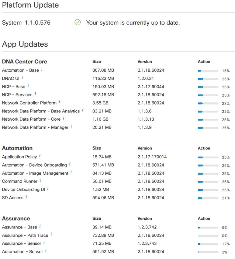
Table of Contents
Table of Contents
Software-Defined Access introduction............................................................................................. 1
Implementation overview...................................................................................................................................................2
Design considerations.......................................................................................................................................................3
Additional information........................................................................................................................................................4
Deployment details........................................................................................................................... 5
Installing SD-Access network management......................................................................................................................6
Installing DNA Center...............................................................................................................................................6
Installing Identity Services Engine nodes.............................................................................................................. 22
Integrating Identity Services Engines with DNA Center......................................................................................... 28
Install SD-Access wireless LAN controllers.......................................................................................................... 31
Deploying SD-Access.................................................................................................................................................... 35
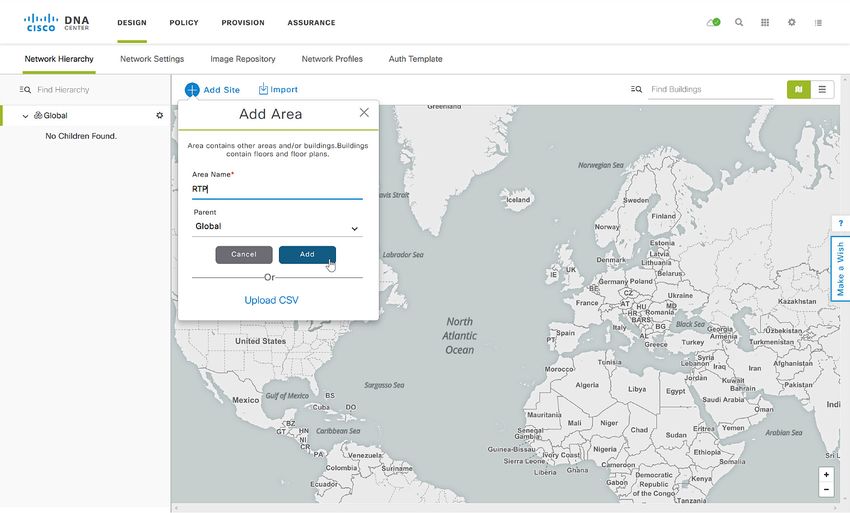
Using DNA Center for initial network design and discovery.................................................................................. 35
Creating segmentation and policy for the SD-Access network............................................................................. 45
Preparing the network for automation................................................................................................................... 48
Provisioning the SD-Access underlay network..................................................................................................... 63
Provisioning an SD-Access overlay network......................................................................................................... 67
Integrating wireless into SD-Access..................................................................................................................... 78
Appendix A: Product list................................................................................................................. 88
DNA Center........................................................................................................................................................... 88
DNA Center packages.......................................................................................................................................... 88
Identity management............................................................................................................................................ 89
SD-Access fabric border and control plane.......................................................................................................... 89
SD-Access fabric edge ....................................................................................................................................... 90
SD-Access Wireless............................................................................................................................................. 90
LAN Automation switches..................................................................................................................................... 90
Glossary......................................................................................................................................... 91
Cisco Validated Design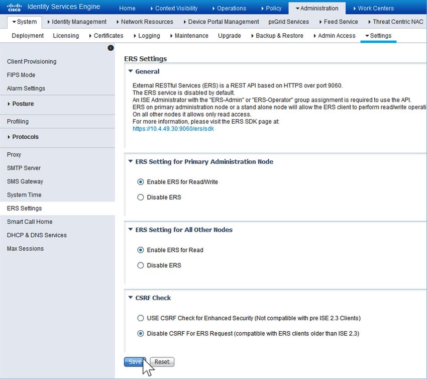
Software-Defined Access introduction

Software-Defined Access introduction
Cisco® Software-Defined Access (SD-Access) is the evolution from traditional campus LAN designs to networks
that directly implement the intent of an organization. SD-Access is enabled with an application package that
runs as part of the Cisco DNA Center™ software for designing, provisioning, applying policy, and facilitating the
creation of an intelligent campus wired and wireless network with assurance. Fabric technology, an integral part
of SD-Access, enables wired and wireless campus networks with programmable overlays and easy-to-deploy
network virtualization, permitting a physical network to host one or more logical networks to meet the design
intent. In addition to network virtualization, fabric technology in the campus network enhances control of network
communications, providing software-defined segmentation and policy enforcement based on user identity and
group membership. Software-defined segmentation is seamlessly integrated using Cisco TrustSec® technology,
providing micro-segmentation through the use of scalable groups within a virtual network. Using DNA Center to
automate the creation of virtual networks reduces operational expenses by simplifying deployment, reduces risk
through integrated security, and improves network performance through assurance and analytics capabilities.
This deployment guide describes how to use Cisco DNA Center to implement an SD-Access network connected
to an existing enterprise network. The virtual networks that SD-Access builds (overlay networks) run on a physical
network (underlay network), creating alternative topologies for connecting devices in the campus LAN. Similarly,
overlay networks are commonly used to provide Layer 2 and Layer 3 logical networks with virtual machine mobility
in data center fabrics (examples: Cisco ACI™, VXLAN/EVPN, and Cisco FabricPath). Overlay networks are also
used in wide-area networks to provide secure tunneling from remote sites (examples: MPLS, DMVPN, and GRE).
This guide helps you understand important elements of automating SD-Access configurations and the integration
of SD-Access into existing networks.
As described in the Software-Defined Access Design Guide, the underlay network is defined by the physical
switches and routers that are used to deploy the SD-Access network. All network elements of the underlay
must establish IP connectivity via the use of a routing protocol. Instead of using arbitrary network topologies and
protocols, the underlay implementation for SD-Access uses a well-designed Layer 3 foundation inclusive of the
campus edge switches (also known as a routed access design), helping ensure the performance, scalability, and
high availability of the network. In SD-Access, the underlay switches support the end-user physical connectivity.
However, end-user subnets are not part of the underlay network—end-user subnets are part of a programmable
Layer 2 or Layer 3 overlay network.
When creating one or more overlay networks, the overlays run across the supporting physical infrastructure of the
underlay network. The data plane traffic and control plane signaling is contained within each virtualized network,
maintaining isolation among the networks in addition to independence from the underlay network. The SD-Access
fabric implements virtualization by encapsulating user traffic in overlay networks, using IP packets that are sourced
and terminated at the boundaries of the fabric. The fabric boundaries include borders for ingress and egress to a
fabric, fabric edge switches for wired clients, and fabric APs for wireless clients.
Because IP-based connectivity within each Layer 3 overlay is an abstraction from the physical connectivity,
multiple IP networks can be a part of each virtual network. You preserve IP address space traffic separation
beyond the fabric border using typical virtualization techniques—including adding devices to remediate addressing
conflicts (typically using network address translation) and enabling communication with permitted common
external IP services such as DNS and the Internet.

Cisco Validated Design                                                                                      page 1
Software-Defined Access introduction

Figure 1. Layer 3 overlay—connectivity logically routed

                                                                        Border Nodes

                                                                           Edge
                                                                           Nodes

                                                                 Logical Layer 3 Overlay

                              Physical Topology

                                                                                                         7104F
In addition to network virtualization, SD-Access integrates Cisco TrustSec technology to enable software-defined
segmentation and policy enforcement based on user identity and group membership. In this deployment, DNA
Center manages the definition of security policies to be rendered into the network infrastructure by Cisco Identity
Services Engine (ISE). Scalable group tags (SGTs) are integrated into the headers used for fabric encapsulation.
For group policies that extend outside of the SD-Access fabric, you configure the propagation of the SGT
information from the fabric border node to the network external to the fabric by either transporting the tags to
Cisco TrustSec aware devices using SGT Exchange Protocol (SXP) or by directly mapping SGTs into the Cisco
Meta Data field in a packet using inline tagging capabilities implemented for connections to the border node.

Implementation overview
Although there are certainly a wide variety of alternative deployment options to the topologies, routing protocols,
and designs shown in this implementation, organizations are encouraged to start their implementations with the
configurations presented and then customize the configurations to fit their needs.
The deployment of the underlay network supporting SD-Access uses a Layer 3 routed access topology. The
example deployment uses the Intermediate System to Intermediate System (IS-IS) routing protocol, bidirectional
forwarding detection (BFD) for fast failure detection, and equal-cost multipath (ECMP) routing using redundant
interconnections for fast network convergence. Layer 2 access designs and Layer 2 EtherChannel must not be
used in the underlay implementation for the SD-Access solution.

Cisco Validated Design                                                                                           page 2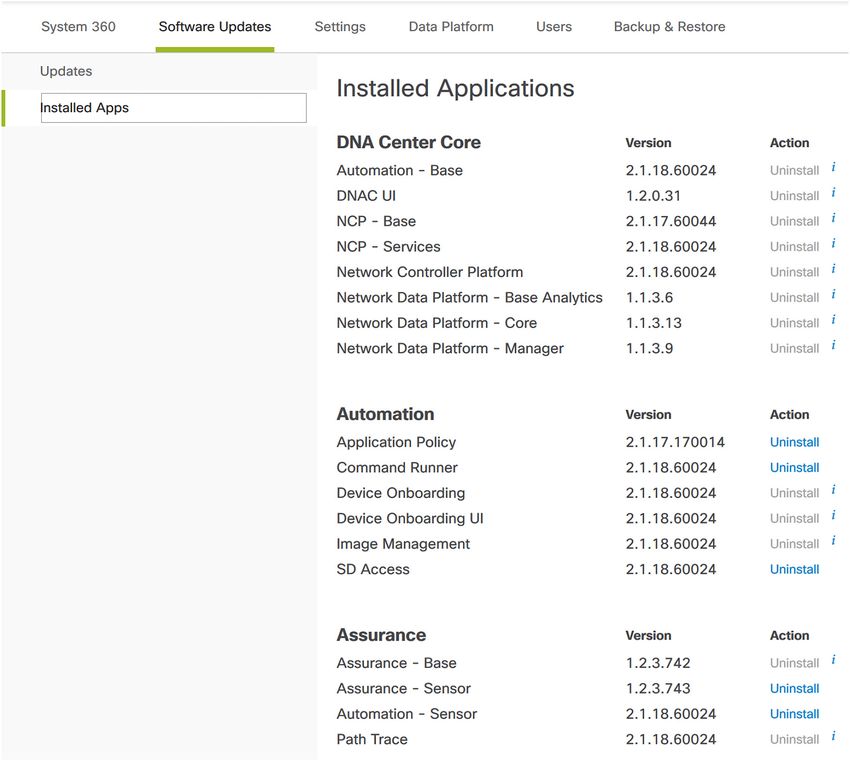
Software-Defined Access introduction

The overlay networks connect with the rest of the enterprise network at the fabric border nodes, and the
deployment example uses switches in the core tier of a campus three-tier (core, distribution, access) network for
that border role. Each overlay network appears as a virtual routing and forwarding (VRF) instance at the border for
connectivity to external networks. You preserve the overlay separation when extending the networks outside of
the fabric by using VRF-lite, maintaining the network separation within devices connected to the fabric and also
on the links between VRF-enabled devices.
Typically, you maintain the separation of overlay networks using VRF-lite when connecting the fabric to external
networks, while still allowing connectivity from some or all overlay networks to services that are available
throughout the enterprise network. These shared services, such as the Internet, domain name services, or data
center applications, often reside within the global routing table or are assigned to a dedicated VRF. The connectivity
from the fabric border to the external networks is often accomplished using a handoff to a fusion router—a device
specifically configured for the role of governing the access between the VRFs and the shared services.
When you consider integrating the campus fabric into an existing enterprise network, the integration choice is
driven by the currently deployed enterprise network design:
  •• Nonvirtualized enterprise network: If the existing enterprise network is not yet virtualized, the
     recommended, validated interconnection between the fabric border and the existing nonvirtualized network
     uses an intermediate fusion router to enable route exchange between the fabric and external domains
     and access to the shared services. Deploy dual fusion routers for increased availability and use Border
     Gateway Protocol (BGP) for exchanging routes among border nodes and fusion routers, which inherently
     accommodates loop avoidance.
  •• Virtualized enterprise network: If the existing enterprise network is already virtualized (for example, using
     Layer 3 VPN), use VRF-lite to extend the VRFs at the campus fabric border nodes into the existing virtualized
     infrastructure, and continue using the techniques available in the existing virtualized network for enabling
     required access to shared services.
In the deployment described, the campus core layer hosts the fabric border functionality. An alternative border
for smaller networks uses a collapsed core/distribution with stackable switches. Using the core tier as the border
allows an overlay network to span across any portion of, or all of, the three-tier campus domain, with the core
being a logical choice as the common exit point for network traffic. The location where traffic exits the fabric as
the default path to all other networks is an external border. An internal border used to access a well-defined set
of networks, such as a data center, and an anywhere border (serving both internal and external border roles), are
not included as part of the described deployment.
If there is a requirement to have another location in the fabric as an alternative exit point for a specific set of
non-default traffic (perhaps a WAN location, for example), additional border devices are used to support the
requirement. The scope of border deployment guidance in this version of the deployment guide is for the more
common external border configurations.

Design considerations
When deploying SD-Access, there are a number of significant deployment decisions to consider prior to starting,
as described in the Software-Defined Access Design Guide. These considerations include:
  •• Are you ready to deploy a Layer 3 (routed) access layer? This deployment assumes a Layer 3 access
     layer deployment model for the network. Although any topology and routing protocol could be used in the
     underlay, the implementation of a well-designed Layer 3 foundation all the way to the campus edge is
     required to ensure support for performance, scalability, and high availability of the network. The DNA Center
     LAN Automation feature is an alternative to manual underlay deployments for new networks, and uses an
     IS-IS routed access design. Though there are many alternative routing protocols, the IS-IS selection offers
     operational advantages such as neighbor establishment without IP protocol dependencies, peering capability
     using loopback addresses, and agnostic treatment of IPv4, IPv6, and non-IP traffic.

Cisco Validated Design                                                                                       page 3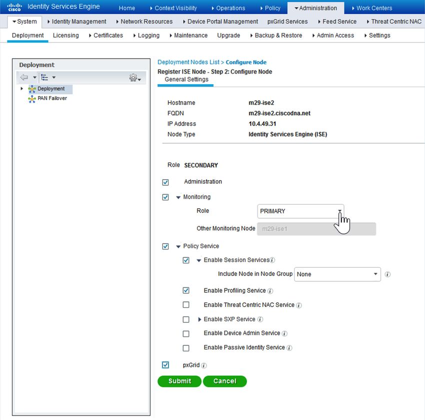
Software-Defined Access introduction

  •• Subnet planning is an integral consideration if you are planning a migration from a Layer 2 access layer to a
     routed access layer.

  •• SD-Access introduces flexibility to the traditional routed access layer. Client subnets in the overlay are
     associated to the closest physical Layer 3 gateway, allowing subnets to stretch through the SD-Access
     fabric. Policies for the overlay allow client subnets to be configured to support a specific function, such as
     connectivity for computers, unified communications, wireless BYOD, or wireless guest networks.

  •• Do you plan to deploy the underlay manually, as an extension to the routing protocol already used throughout
     an organization, or do you intend to use an interior gateway protocol (IGP) that may be unique to the
     fabric underlay? This deployment shows IS-IS as the underlay IGP selection, which is aligned to the LAN
     automation available for new network deployments.

  •• Are there requirements to deploy multiple Layer 3 overlay networks (such as for multitenant use cases
     described in the introduction), or does a single Layer 3 overlay with multiple subnets across the fabric meet
     the requirements? The deployment accommodates both by supporting one or multiple VRFs, including
     handoff outside the fabric domain. Multiple overlays require additional planning for the integration of shared
     services. Plan for and document all overlay subnets and VRFs so that you are prepared to integrate them into
     your Dynamic Host Configuration Protocol (DHCP) services.

  •• Have you identified the appropriate locations for the edge, border, and control plane roles in your network?
     Do you have the proper platforms in place to support those fabric roles? Full discussion of these platforms
     and roles is covered in the associated Software-Defined Access Design Guide. It is important to understand
     that, unlike in a pilot deployment, a production deployment will present operational challenges if you
     deploy the border role in one location and later decide to relocate the border role to another location, so
     careful consideration of the future scope of the fabric boundaries is important. In the validated deployment
     described, the most common scenarios with supported platforms are shown, and Appendix A: Product list
     lists the equipment specifically validated for roles in this deployment.

Additional information
If you didn’t get this guide from Cisco Design Zone, you can check for the latest version of this guide.
You can find the Software-Defined Access Design Guide, User-to-Data Center Access Control Using TrustSec
Deployment Guide, and related design guides, deployment guides, and white papers in the Design Zone at the
following page:
https://www.cisco.com/go/designzone

Cisco Validated Design                                                                                        page 4
Deployment details

Deployment details

The enterprise network integrated with the described campus fabric deployment is nonvirtualized and runs
Enhanced Interior Gateway Routing Protocol (EIGRP) as a routing protocol. IP prefixes from the campus, including
shared services, must be available to both the fabric underlay and overlay networks while maintaining isolation
among overlay networks. To maintain the isolation, VRF-Lite extends from the fabric border nodes to a set of fusion
routers. The fusion routers implement VRF route leaking using a BGP route target import and export configuration
and perform mutual redistribution with EIGRP in the enterprise network and with BGP to the campus fabric. A
route-map configuration for dynamic tagging and filtering of redistributed routes provides a simple and dynamic
way to prevent routing loops while accommodating multiple redistribution points in the high-availability design.

Figure 2. Validation topology
                                                                                  Identity Store
                                                                                 ISE + AD/Other

  Guest Fabric                                                   DNA Center                                  DNS/DHCP
   Border and                         DMZ       Internet
  Control Plane

                                                                                 L2 MEC

                                                                           Shared       Wireless
                                                                          Services   LAN Controller(s)
                           Fusion Routers/
                             Super Core          QFP       QFP

                                                                        Fabric Border + Control-
                                                                              Plane Nodes

                  Fabric Edge Nodes                                            Fabric Intermediate
                                                                                Nodes (Underlay)

Cisco Validated Design                                                                                             page 5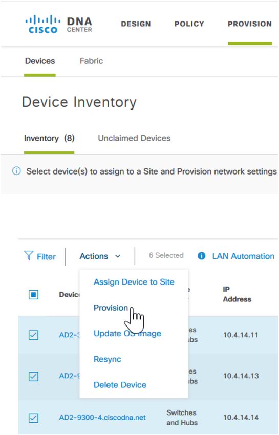
Deployment details

Installing SD-Access network management
The Cisco SD-Access solution described uses a single DNA Center hardware appliance, prepared for future
inclusion as part of a three-node cluster. For this solution, the DNA Center software integrates with two ISE nodes
configured for redundancy and dedicated to the SD-Access deployment, as detailed in the installation. To support
SD-Access Wireless, the solution includes two wireless LAN controllers (WLCs) for controller redundancy.
Before you begin, you must identify the following:
   •• IP addressing and network connectivity for all controllers being deployed: DNA Center must have Internet
      access for system updates from the Cisco cloud repository.

   •• A network-reachable Network Time Protocol (NTP) server, used during DNA Center installation to help
      ensure reliable digital certificate operation for securing connections.

   •• Certificate server information, when self-signed digital certificates are not used.

           Installing DNA Center
 Process

           1. Connect and configure the DNA Center hardware appliance
           2. Check the DNA Center version
           3. Migrate the DNA Center platform to Release 1.2
           4. Upgrade the DNA Center 1.2 packages

The DNA Center appliance has 10-Gbps SFP+ modular LAN on motherboard (mLOM) interfaces and integrated
copper interfaces available for network connectivity. Use the following table to assist with IP address assignment
and connections. The validation shows a single-node cluster that uses a virtual IP (VIP) configured on a single
DNA Center appliance, easing future migration to a three-node cluster. You do not need to physically connect
the intra-cluster communications port for a single-node cluster configuration. For provisioning and assurance
communication efficiency, DNA Center should be installed in close network proximity to the greatest number of
devices being managed.

Figure 3. Rear view of the DNA Center appliance — DN1-HW-APL

Cisco Validated Design                                                                                     page 6
Deployment details

Table 1. DNA Center server LAN Ethernet interface assignments (left to right, from rear)

                        PORT 2                 PORT 1               M                   1                    2
                        mLOM                   mLOM                 Integrated          Integrated           Integrated
                        SFP+ 10 Gbps           SFP+ 10 Gbps         RJ-45               RJ-45                RJ-45

 Wizard name            enp10s0                enp9s0               —                   enp1s0f0             enp1s0f1

 Use                    Intra-cluster          Enterprise           Cisco               Optional             Optional
                        communications         network              Integrated          dedicated            isolated
                                               infrastructure       Management          management           enterprise
                                                                    Controller out-     network for          network
                                                                    of-band server      web access
                                                                    appliance
                                                                    management
 Example                —                      10.4.49.25           —                   —                    —
 cluster VIP                                   255.255.255.0
 address
 Example                192.168.127.1          10.4.49.26           10.204.49.25        Unused in this       Unused in this
 interface              255.255.255.248        255.255.255.0        255.255.255.0       example              example
 address

             Tech tip

             Connecting DNA Center to your network using a single network interface (enterprise network
             infrastructure, mLOM PORT1) simplifies the configuration by requiring only a default gateway and by
             avoiding the need to maintain a list of static routes for any additional interfaces connected. When
             you use additional optional interfaces (for example, to separate the networks for infrastructure
             provisioning and administrative access to DNA Center), the network route changes may require that
             you reconfigure the appliance. To update static routes in DNA Center after the installation, follow
             the procedure to reconfigure the appliance in the Cisco Digital Network Architecture Center Appliance
             Installation Guide for your installed version.

Reserve an arbitrary private IP space at least 20 bits of netmask in size that is not used elsewhere in the network.
Divide the /20 address space into two /21 address spaces and use them in a later setup step for services
communication among the processes running in a DNA Center instance. Both single-node cluster and three-
node cluster configurations require the reserved IP address space.
The DNA Center appliance also must have Internet connectivity, either directly or via a web proxy, to obtain software
updates from the Cisco cloud repository. Internet access requirements and optional proxy server setup requirements
are detailed in the applicable version of the Cisco Digital Network Architecture Center Appliance Installation Guide.

             Caution

             The installation described assumes a new installation of DNA Center. If you already have DNA Center
             deployed and managing devices in your network, do not use the steps in this Install DNA Center
             process. Instead, you must refer to the release notes on Cisco.com for the correct procedure for a
             successful upgrade to your desired release.

             https://www.cisco.com/c/en/us/support/cloud-systems-management/dna-center/products-release-
             notes-list.html

Cisco Validated Design                                                                                               page 7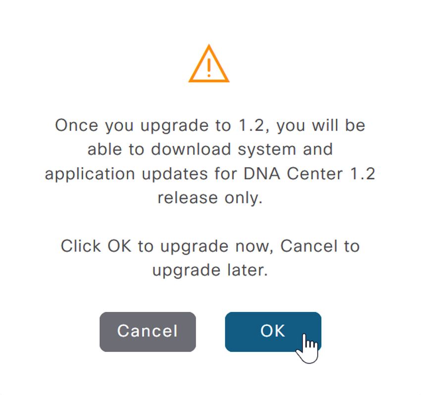
Deployment details

 Procedure 1        Connect and configure the DNA Center hardware appliance

Step 1: Connect the DNA Center hardware appliance to a Layer 2 access switch port in your network, by:

          •• Using the 10Gb port labeled PORT 1 on the mLOM card (named enp9s0 in the wizard)
          •• Using the Cisco Integrated Management Controller (IMC) port (labeled M on the embedded
             Ethernet ports)

Step 2: Connect any other ports needed for the deployment, such as the dedicated web management port,
an isolated enterprise network port, or a cluster configuration port. These optional ports are not used for the
deployment described.

The following example steps are described in detail with all options within the Installation Guide for the appliance
software version. Use the guide to configure Cisco IMC on the appliance during first boot, along with the credentials
required for Cisco IMC access. The Installation Guide describes the complete set of options, including joining a host
to another host to create a cluster and configuring the left port (labeled PORT 2 on the mLOM card, and named
enp10s0 in the wizard) for intra-cluster communications. The example that follows configures a single appliance for a
single-node cluster or the first appliance for a three-node cluster deployment, without configuring a network proxy.
Step 3: Boot the DNA Center hardware appliance. A welcome message appears.

          Welcome to the Maglev Configuration Wizard!
Step 4: Press Enter to accept the default choice, Start a DNA-C Cluster.

Step 5: Continue by accepting the wizard default choices, while supplying information for the following steps
within the wizard (the wizard steps are in order but are not sequential):

          •• In wizard STEP #4, selection for NETWORK ADAPTER #1 (enp10s0):
             This interface is used for clustering—configure clustering to easily allow for the future capability, even
             if you don’t need clustering initially. Fill in the information for the Host IP Address and Netmask (a
             /29 size network or larger covers a three-member cluster), use the spacebar to select Cluster Link,
             do not fill in any other fields, and then select next >> to continue.

          Host IP Address:
             192.168.127.1
          Netmask:
             255.255.255.248
          Default Gateway IP Address:
             [blank]
          DNS Servers:
             [blank]
          Static Routes:
             [blank]
          Cluster Link
             [use spacebar to select]
          Configure IPv6 address
             [blank]

Cisco Validated Design                                                                                         page 8
Deployment details
•• In wizard STEP #4, selection for OPTIONAL - NETWORK ADAPTER #2 (enp1s0f0):
This interface can be used as a dedicated management interface for administrative web access to DNA
Center. If you are using this option (which requires static route configuration), fill in the information; otherwise
leave all selections blank, and then select next >> to continue.
•• In wizard STEP #4, selection for OPTIONAL - NETWORK ADAPTER #3 (enp1s0f1):
This interface is available for use with a separated network to the Internet cloud repository with a static route.
Unless you require this connectivity, leave all selections blank, and select next >> to continue.
•• In wizard STEP #4, selection for OPTIONAL - NETWORK ADAPTER #4 (enp9s0):
Use this interface for communications with your network infrastructure. Supply at least the Host IP Address,
Netmask, Default Gateway IP Address, and DNS Servers, if you are not using the single interface with
default gateway, supply Static Routes, and then select next >> to continue.
Host IP Address:
10.4.49.26
Netmask:
255.255.255.0
Default Gateway IP Address:
10.4.49.1
DNS Servers:
10.4.49.10
Static Routes:
[blank for single interface installation]
Cluster Link
[blank]
Configure IPv6 address
[blank]
The wizard displays an informational message.
The wizard will need to shutdown the controller in order to validate…
Step 6: Select proceed >> to continue with the network validation. The installation validates gateway reachability.
Please wait while we validate and configure host networking...
Step 7: After the wizard network validation completes, continue entering initial configuration values. For
all installations, create a cluster configuration to facilitate future migration. To add appliances into a cluster
configuration, refer to the Installation Guide.
•• In wizard STEP #11 , MAGLEV CLUSTER DETAILS:
Cluster Virtual IP address
10.4.49.25
Cisco Validated Design page 9Deployment details
•• In wizard STEP #13 , USER ACCOUNT SETTINGS:
Linux Password: *
[linux password]
Re-enter Linux Password: *
[linux password]
Password Generation Seed:
[skip this entry]
Auto Generated Password:
[skip this entry]
Administrator Passphrase: *
[DNAC administrator password]
Re-enter Administrator Passphrase: *
[DNAC administrator password]
Step 8: In wizard STEP #14, NTP SEVER SETTINGS, you must supply at least one active NTP server, which is
tested before the installation can proceed.
NTP Servers: *
10.4.0.1 10.4.0.2
Step 9: Select next >>. The installation validates connectivity to the NTP servers.
Validating NTP Server: 10.4.0.1
Step 10: In wizard STEP #16 , MAGLEV ADVANCED SETTINGS, you assign unique IP networks that are not part
of the enterprise network, which are used by DNA Center to manage its own API services and cluster services.
The minimum recommended size for each is a network with a 21-bit netmask to accommodate the large numbers
of different services with unique IP addresses that communicate with one another.
Services Subnet: *
192.168.240.0/21
Cluster Services Subnet: *
192.168.248.0/21
Select next >>. The wizard displays an informational message.
The wizard is now ready to apply the configuration on the controller.
Step 11: Disregard any additional warning messages about existing disk partitions. Select proceed >> to
apply the configuration and complete the installation. You should not interact with the system until the installation
is complete.
A number of status messages scroll by during the installation, the platform boots the installed image and
configures the base processes for the first time, which can take multiple hours. When installation and
configuration is complete, a login message is displayed.
Welcome to the Maglev Appliance (tty1)
Cisco Validated Design page 10Deployment details
Step 12: Log in with the maglev user from the Cisco IMC console, or alternatively from an SSH session on port
2222 to the host IP address as assigned during the installation.
maglev-master-1 login: maglev
Password: [password assigned during installation]
Step 13: Verify that processes are deployed.
$ maglev package status
For the validated version, all packages are DEPLOYED initially, except for any NOT_DEPLOYED packages listed,
including the following, which vary depending on your installation version:
application-policy
sd-access
sensor-automation
You install other required components in later steps.
Procedure 2 Check the DNA Center version
Step 1: Connect to the DNA Center web UI by directing a web browser to the Cluster Virtual IP address you
supplied in the previous procedure (example: https://10.4.49.25/). While processes are launched after installation,
you may have to wait for some time before the web server is available to serve your first request.
Step 2: At the Username line enter admin, at the Password line enter the DNA Center administrator password
that you assigned using the Maglev Configuration Wizard, and then click Log In.
Cisco Validated Design page 11Deployment details Step 3: At the prompt to reset the password, choose a new password or skip to the next step. Step 4: At the Welcome to DNA Center prompt, provide a Cisco.com ID and password. The ID is used to register software downloads and receive system communications. If you skip this step because you do not have an ID or plan to add one later by using Settings (gear) > System Settings > Settings > Cisco Credentials, features such as SWIM, Telemetry, and Licensing will be unable to function properly. Additionally, credentials are required for downloading software packages as described in the software migration and update procedures. Step 5: In the previous step, if you did not enter an ID with Smart Account access with privileges for managing Cisco software licenses for your organization, a Smart Account prompt displays. Enter a Cisco.com ID associated with a Smart Account or click Skip. Step 6: If you have an Infoblox or Bluecat IPAM server, enter the details at the IP Address Manager prompt and click Next. Otherwise, click Skip. Step 7: At the Terms and Conditions display, click Next, and then at the Ready to go! display, click Go. Cisco Validated Design page 12
Deployment details

Step 8: At the main DNA Center dashboard, click the settings (gear) icon, and then click About DNA Center.

Step 9: Check that the version is at least 1.1.6. If your version is earlier than 1.1.6, contact support to reimage
your DNA Center appliance to version 1.1.6 or later before continuing. Version 1.1.6 is the minimum software
requirement to upgrade to version 1.2.3, shown in a later step.

Cisco Validated Design                                                                                     page 13
Deployment details

 Procedure 3          Migrate the DNA Center platform to Release 1.2

Optional
If you are running at least version 1.1.6, but are not running the desired 1.2.3 version of DNA Center, use the
Cisco cloud repository to upgrade the DNA Center appliance to the required version.

           Tech tip

           This procedure shows the upgrade for DNA Center release 1.1 versions (minimum of 1.1.6) to
           version 1.2.3. For other software versions, refer to the release notes on Cisco.com for the correct
           procedure for a successful upgrade to the target version from the installed version.

           https://www.cisco.com/c/en/us/support/cloud-systems-management/dna-center/products-release-
           notes-list.html

Step 1: At the main DNA Center dashboard, click Add applications.

The Application Management – Packages and Updates screen displays. This screen is used to install
packages, adding functionality to the controller, including SD-Access.

           Tech tip

           The DNA Center release notes include access requirements for connecting DNA Center to the
           Internet behind a firewall to download packages from the cloud catalog server. The release notes are
           on Cisco.com at:

           https://www.cisco.com/c/en/us/support/cloud-systems-management/dna-center/products-release-
           notes-list.html

DNA Center automatically connects to the Cisco cloud repository to find the latest updates. You can use the
Refresh button to reveal any updates that are found over time.

Cisco Validated Design                                                                                            page 14
Deployment details
Step 2: Click the settings (gear) icon, click System Settings, and then navigate to App Management >
System Updates. The Application Management – System Updates screen is displayed.
Tech tip
Illustrations are installation examples. Software versions used for validation are listed in Appendix A:
Product list.
Step 3: Click the Switch Now button, and then acknowledge that the migration to 1.2 versions is irreversible by
clicking OK.
Cisco Validated Design page 15Deployment details
DNA Center connects to the cloud catalog server.
After DNA Center finishes connecting to the 1.2 cloud catalog server, the page is refreshed with the 1.2 release
option. You may use the Refresh button to manually update the screen. The system package Available Update
version displayed is at least 1.1.0.576, which corresponds to release 1.2 of the DNA Center platform.
Step 4: To the right of the available update version number, click the Install button.
Caution
The System package within the System Updates section is the only package you download or
update during the initial system update. After the installation of the system is complete, you then
download and install the application package updates.
A message appears stating that the system update download has initiated. The Status shows DOWNLOADING_
UPDATES for many minutes. After the download completes, the installation starts automatically with a status
showing INSTALLING_UPDATES, which can take more than an hour. Use the Refresh button to check the status.
At the end of the installation, refresh the browser to view the new UI.
Cisco Validated Design page 16Deployment details Procedure 4 Upgrade the DNA Center 1.2 packages After the DNA Center platform is converted to release 1.2, you upgrade the system to the latest packages. The release 1.2 UI has some improvements that are used during the upgrades. Step 1: Connect to the DNA Center web UI, and navigate to the main dashboard. Step 2: In the top-right of the DNA Center release 1.2 dashboard, select the software updates cloud, and then click Go to Software Updates. Release 1.2 displays an enhanced Platform Update screen. Step 3: Check the top right of the Platform Update screen, on the same row as App Updates, to see if the Download All button is grayed out. If the button is grayed out, enable your browser to display the new UI by either clearing your browser cache and reloading the browser window or using a private or incognito mode browser instance before continuing to the next step. Step 4: At the top right of the Platform Update screen, on the same row as App Updates, click Download All. Do not select any of the other Download All buttons on the screen. Cisco Validated Design page 17
Deployment details

Step 5: At the popup, select Continue to confirm the update operation. At the second System Readiness
Check popup, select Continue. The screen updates, showing all of the packages that are being downloaded.

The interface updates with the package installation status, and at the top of the screen the cloud icon also informs
users navigating to any screen of the status.
Before proceeding to the next step, refresh the screen until there are no longer any packages that are
downloading. The download and associated package dependency download and installation can take over an hour
to complete. If there are still package dependencies for updates, the Download All button is displayed again.

Cisco Validated Design                                                                                   page 18
Deployment details

Step 6: After the downloads complete, if any additional packages are listed for updates, repeat the previous two
steps until the Download All button is replaced with an Install All button that is not grayed out.

Step 7: After the new versions of the packages are downloaded, at the top right of the Platform Update
screen, on the same row as App Updates, click Install All, on the popup click Continue, and then, on the
System Readiness Check popup, click Continue. An informational message appears stating that the Packages
installation will start soon…, and the installation begins.

The remaining package updates begin. The browser refreshes automatically, showing the updated status for each
package. The update process can take over an hour to complete.

           Tech tip

           Packages must be updated in a specific order to appropriately address package interdependencies.
           Allow DNA Center to handle dependencies by selecting and updating all package updates at once.
           The Installation Guide explains how to use the Maglev CLI to force a download retry for any stalled
           download.

While the packages are installing, which takes some time, you may work in parallel on the next process for
installing the Identity Services Engine nodes.
All of the application package updates are installed when the Software Updates > Updates screen no longer
shows any available packages listed under App Updates and the cloud icon in the top right of the screen displays
a green checkmark.

Do not continue to the next step until all packages are installed.

Cisco Validated Design                                                                                           page 19
Deployment details Step 8: Navigate to Software Updates > Installed Apps to see that all packages are installed. The packages are grouped by package type. Cisco Validated Design page 20
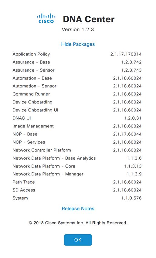
Deployment details

Step 9: At the main DNA Center dashboard, click the settings (gear) icon, click About DNA Center, and then
click Show Packages. This view is useful for comparing to the release notes, which are available by clicking on
the Release Notes text.

With all application packages installed, the SD-Access functionality is available to use, and integration with the
installed ISE nodes can proceed.

Cisco Validated Design                                                                                     page 21
Deployment details

           Installing Identity Services Engine nodes
 Process

           1. Install ISE server images
           2. Configure roles for ISE nodes
           3. Register ISE node 2 and configure roles

The SD-Access solution described in this guide uses two ISE nodes in a high-availability standalone
configuration dedicated to the SD-Access network and integrated into DNA Center management. The first ISE
node has the primary policy administration node (PAN) persona configuration and the secondary monitoring
and troubleshooting (MnT) persona configuration. The second ISE node has the secondary PAN persona
configuration and the primary MnT persona configuration. Both nodes include policy services node (PSN) persona
configurations. You must also enable pxGrid and External RESTful Services (ERS) on the ISE nodes.

Table 2. ISE node configurations

  ISE Node 1                                                          ISE Node 2

  Primary PAN                                                         Secondary PAN
  Secondary MnT                                                       Primary MnT
  PSN                                                                 PSN
  pxGrid                                                              pxGrid

  ERS Services                                                        ERS Services

              Tech tip

              There are specific ISE software versions required for compatibility with DNA Center. To be able to
              integrate with an existing ISE installation, you must first ensure that the existing ISE is running at least
              the minimum supported version. An ISE integration option, which is not included in this validation, is to
              stand up a new ISE instance as a proxy to earlier versions of ISE.

              The versions of ISE and DNA Center validated in HA standalone mode for this guide are listed in
              Appendix A: Product list. You may find alternative recommended images by searching Cisco.com for
              SD-Access Hardware and Software Compatibility Matrix.

 Procedure 1             Install ISE server images

Step 1: On both ISE nodes, boot and install the ISE image.

Step 2: On the console of the first ISE node, at the login prompt, type setup, and then press Enter.

             **********************************************
             Please type ‘setup’ to configure the appliance
             **********************************************
             localhost login: setup

Cisco Validated Design                                                                                                       page 22
Deployment details
Step 3: Enter the platform configuration parameters.
Press ‘Ctrl-C’ to abort setup
Enter hostname[]: m29-ise1
Enter IP address []: 10.4.49.30
Enter IP netmask[]: 255.255.255.0
Enter IP default gateway[]: 10.4.49.1
Enter default DNS domain[]: ciscodna.net
Enter Primary nameserver[]: 10.4.49.10
Add secondary nameserver? Y/N [N]: N
Enter NTP server[time.nist.gov]: 10.4.0.1
Add another NTP server? Y/N [N]: Y
Enter NTP server[time.nist.gov]: 10.4.0.2
Add another NTP server? Y/N [N]: N
Enter system timezone[UTC]: UTC
Enable SSH service? Y/N [N]: Y
Enter username[admin]: admin
Enter password: [admin password]
Enter password again: [admin password]
Copying first CLI user to be first ISE admin GUI user…
Bringing up network interface...
Pinging the gateway...
Pinging the primary nameserver...
Do not use ‘Ctrl-C’ from this point on...
Installing Applications...
=== Initial Setup for Application: ISE ===
Additional installation messages appear, and then the server reboots.
Rebooting...
Step 4: Repeat steps 2 and 3 on the second ISE node, using the appropriate parameters for it.
The systems reboot automatically and display the Cisco ISE login prompt.
localhost login:
Cisco Validated Design page 23Deployment details Procedure 2 Configure roles for ISE nodes Step 1: On the first ISE node, login using a web browser and the configured username and password, and then accept any informational messages. https://m29-ise1.ciscodna.net/ Step 2: Navigate to Administration > System > Deployment, and then click OK to the informational message. Step 3: Click on the ISE node hostname, and then under Role, click Make Primary. Step 4: Select pxGrid, and then click Save. Procedure 3 Register ISE node 2 and configure roles Integrate the additional ISE node by using the same ISE administration session started on the first node. Step 1: Refresh the view by navigating again to Administration > System > Deployment, and then under the Deployment Nodes section, click Register. A screen displays allowing registration of the second ISE node into the deployment. Cisco Validated Design page 24
Deployment details

Step 2: Enter the ISE fully-qualified domain name Host FQDN (m29-ise2.ciscodna.net), User Name (admin),
and Password ([admin password]), and then click Next.

Step 3: If you are using self-signed certificates, click Import Certificate and Proceed. If you are not using self-
signed certificates, follow the instructions for importing certificates and canceling this registration, and then return
to the previous step.

Step 4: On the Register ISE Node - Step 2: Configure Node screen, under Monitoring, change the role for
this second ISE node to PRIMARY, at the bottom check pxGrid, and then click Submit.

The node configuration is saved.

Cisco Validated Design                                                                                       page 25
Deployment details

Step 5: Click OK to the notification that the data is to be synchronized to the node and the application server on
the second node will restart.

The synchronization and restart of the second node can take more than ten minutes to complete. You can use
the refresh button on the screen to observe when the node returns from In Progress to a Connected state to
proceed to the next step.

Step 6: Check Cisco.com for ISE release notes, download any patch required for your installation, and install the
patch by navigating in ISE to Administration > System > Maintenance > Patch Management, click Install, click
Browse, browse for the patch image, and then click Install. The patch installs node-by-node to the cluster, and
each cluster node reboots.

Step 7: After the ISE web interface is active again, check progress of the patch installation by navigating to
Administration > System > Maintenance > Patch Management, select the patch, and then select Show Node
Status. Use the Refresh button to update status until all nodes are in Installed status, and then proceed to the
next step.

Cisco Validated Design                                                                                   page 26
Deployment details

Step 8: Navigate to Administration > System > Settings, on the left pane navigate to ERS Settings, under
ERS Setting for Primary Administration Node select Enable ERS for Read/Write, accept any dialog box
that appears, under ERS Setting for All Other Nodes select Enable ERS for Read, under CRSF Check select
Disable CSRF for ERS Request, and then click Save. Accept any additional dialog box that appears.

The ERS settings are updated, and ISE is ready to be integrated with DNA Center.

Cisco Validated Design                                                                           page 27
Deployment details
 Process

           Integrating Identity Services Engines with DNA Center
           1. Configure DNA Center authentication and policy servers

Integrate ISE with DNA Center by defining ISE as an authentication and policy server to DNA Center and
permitting pxGrid connectivity from DNA Center into ISE. Integration enables information sharing between the two
platforms, including device information and group information, and allows DNA Center to define policies to be
rendered into the network infrastructure by ISE.

              Tech tip

              The validation includes DNA Center integration with ISE servers as a requirement for automation of
              the assignment of edge ports to VNs and policy configuration, including the deployment of scalable
              group tags and group-based policies.

 Procedure 1             Configure DNA Center authentication and policy servers

Step 1: Log in to the DNA Center web interface, at the top-right corner select the gear icon, and then navigate
to System Settings.

Cisco Validated Design                                                                                             page 28
Deployment details
Step 2: Navigate to Settings > Authentication and Policy Servers, and then click the + Add button.
Tech tip
The next step for integrating an ISE installation is the same whether you use a high-availability
standalone ISE deployment, as validated, or a distributed ISE deployment. The shared secret
chosen needs to be consistent with the shared secret used across the devices in the network for
communicating with the authentication, authorization, and accounting (AAA) server. The username
and password are used for DNA Center to communicate with ISE using SSH, and must be the default
super admin account that was created during the ISE installation.
Step 3: In the Add AAA/ISE SERVER display, enter the ISE node 1 (primary PAN) Server IP Address (example:
10.4.49.30) and Shared Secret, toggle the Cisco ISE selector, enter the ISE Username (example: admin), enter
the ISE Password, enter the ISE fully qualified domain name for FQDN, enter Subscriber Name (example: dnac),
leave the SSH Key blank, and then click Apply.
Cisco Validated Design page 29Deployment details
Tech tip
Many organizations use TACACS for management authentication to network devices, which is not
covered in this validation. If you intend to enable TACACS on the same ISE server being used for
RADIUS client authentication, then you integrate it with DNA Center during this step also by using
the View Advanced Settings drop down menu. ISE configuration information for enabling TACACS
integration is found within ISE by navigating to Work Centers > Device Administration > Overview.
During communication establishment, status from DNA Center displays Creating AAA server… and then Status
displays INPROGRESS. Use the Refresh button until communication establishes with ISE and the server displays
ACTIVE status. If communication is not established, an error message displays with information reported from
ISE regarding the problem to be addressed before continuing. You can also see the communication status by
navigating from the gear icon to System Settings > System 360. Under External Network Services, the Cisco
ISE server shows in Available status.
With communications established, DNA Center requests a pxGrid session with ISE.
Step 4: Log in to ISE, and then navigate to Administration > pxGrid Services.
The client named dnac is now showing Pending in the Status column.
Step 5: Check the box next to dnac, above the list click Approve, and then click Yes to confirm.
A success message displays, and the Pending status changes to Online (XMPP). You can additionally verify
that the integration is active by expanding the view for the client and observing two subscribers, Core and
TrustSecMetaData.
If ISE is integrated with DNA Center after scalable groups are already created in ISE, in addition to the default
groups available, any existing ISE groups are also visible by logging in to DNA Center and navigating to Policy >
Registry > Scalable Groups. Existing ISE policies are not migrated to DNA Center.
Cisco Validated Design page 30Deployment details
Process
Installing SD-Access wireless LAN controllers
1. Configure the WLC Cisco AireOS platforms using the startup wizard
For this deployment, dedicate the WLCs to SD-Access Wireless connectivity by integrating them natively with the
fabric. The WLCs use link aggregation to connect to a redundant Layer 2 shared services distribution outside of
the SD-Access fabric, as described in the Campus LAN and Wireless LAN Design Guide. Configure a pair of Cisco
WLCs with high availability stateful switchover (HA SSO) resiliency, and all of the network connectivity should be in
place before starting the configuration procedure.
Redundant WLCs should be connected to a set of devices configured to support the Layer 2 redundancy suitable
for the HA SSO WLCs, such as a switch stack, Cisco Virtual Switching System, or Cisco StackWise® Virtual,
which may exist in a data center or shared services network. For maximum resiliency, redundant WLCs should not
be directly connected to the Layer 3 border nodes.
Tech tip
The SD-Access solution described supports transport of only IP frames in the Layer 2 overlays that
are used for WLAN, without Layer 2 flooding of broadcast and unknown multicast traffic. Without
broadcasts from the fabric edge, Address Resolution Protocol (ARP) functions by using the fabric
control plane for MAC-to-IP address table lookups. For transport of non-IP frames and Layer 2
flooding, see the release notes for your software version in order to verify updated support.
Tech tip
Adding WLAN as part of the SD-Access solution while using Cisco Catalyst® 6800 Series fabric
border devices requires the software releases listed in Appendix A: Product list. If the devices do not
have software supporting the wireless control plane, you must use separate control plane devices that
do include wireless support. See the release notes for any changes to WLAN Layer 2 control plane
support when using the Cisco Catalyst 6800 Series.
Procedure 1 Configure the WLC Cisco AireOS platforms using the startup wizard
Perform the initial configuration using the CLI startup wizard.
After powering up the WLC, you should see the following on the WLC console. If not, type - (dash) followed by
Enter repeatedly until the startup wizard displays the first question.
Welcome to the Cisco Wizard Configuration Tool
Use the ‘-‘ character to backup
Step 1: Terminate the auto-install process.
Would you like to terminate autoinstall? [yes]: YES
Step 2: Enter a system name. Do not use colons in the system name, and do not leave the default name.
System Name [Cisco_7e:8e:43] (31 characters max): SDA-WLC-1
Cisco Validated Design page 31Deployment details
Step 3: Enter an administrator username and password.
Tech tip
Use at least three of the following character classes in the password: lowercase letters, uppercase
letters, digits, and special characters.
Enter Administrative User Name (24 characters max): admin
Enter Administrative Password (24 characters max): [password]
Re-enter Administrative Password : [password]
Step 4: Use DHCP for the service port interface address.
Service Interface IP address Configuration [static] [DHCP]: DHCP
Step 5: Enable Link Aggregation (LAG).
Enable Link Aggregation (LAG) [yes][NO]: YES
Step 6: Enter the management interface IP address, mask, and default router. The IP address for the secondary
controller of an HA SSO pair is used only temporarily until the secondary WLC downloads the configuration from
the primary and becomes a member of the HA controller pair.
Management Interface IP Address: 10.4.174.26
Management Interface Netmask: 255.255.255.0
Management interface Default Router: 10.4.174.1
Step 7: Configure the Management Interface VLAN Identifier.
Management Interface VLAN Identifier (0 = untagged): 174
Step 8: Configure the Management Interface Port Number. The displayed range varies by WLC model. This
number is arbitrary after enabling LAG, because all management ports are automatically configured and participate
as one LAG, and any functional physical port in the group can pass management traffic.
Management Interface Port Num [1 to 2]: 1
Step 9: Enter the DHCP server for clients. (Example: 10.4.48.10)
Management Interface DHCP Server IP Address: 10.4.48.10
Step 10: You do not need to enable HA SSO in this step. DNA Center automates the HA SSO controller
configuration during device provisioning.
Enable HA (Dedicated Redundancy Port is used by Default)[yes][NO]: NO
Step 11: The WLC uses the virtual interface for mobility DHCP relay, guest web authentication, and inter-
controller communication. Enter an IP address that is not used in your organization’s network.
Virtual Gateway IP Address: 192.0.2.1
Step 12: Enter a multicast address that will be used by each AP to subscribe to IP multicast flows coming from the
WLC. This address will be used only when configuring the IP multicast delivery method called multicast-multicast.
Multicast IP Address: 239.1.1.1
Cisco Validated Design page 32Deployment details
Tech tip
The multicast address must be unique for each controller or HA pair in the network. The multicast
address entered is used as the source multicast address, which the access points registered to the
controller use for receiving wireless user-based multicast streams.
Step 13: Enter a name for the default mobility and RF group.
Mobility/RF Group Name: SDA-Campus
Step 14: Enter an SSID for the data WLAN. This is used later in the deployment process.
Network Name (SSID): SDA-Data
Step 15: Disable DHCP Bridging Mode.
Configure DHCP Bridging Mode [yes][NO]: NO
Step 16: Enable DHCP snooping.
Allow Static IP Addresses [YES][no]: NO
Step 17: Do not configure the RADIUS server now. You will configure the RADIUS server later using the GUI.
Configure a RADIUS Server now? [YES][no]: NO
Warning! The default WLAN security policy requires a RADIUS server.
Please see documentation for more details.
Step 18: Enter the country code where you are deploying the WLC.
Enter Country Code list (enter ‘help’ for a list of countries) [US]: US
Step 19: Enable all of the required wireless networks.
Enable 802.11b network [YES][no]: YES
Enable 802.11a network [YES][no]: YES
Enable 802.11g network [YES][no]: YES
Step 20: Enable the radio resource management (RRM) auto-RF feature.
Enable Auto-RF [YES][no]: YES
Step 21: Synchronize the WLC clock to your organization’s NTP server.
Configure a NTP server now? [YES][no]:YES
Enter the NTP server’s IP address: 10.4.0.1
Enter a polling interval between 3600 and 604800 secs: 86400
Step 22: Do not configure IPv6.
Would you like to configure IPv6 parameters[YES][no]:NO
Cisco Validated Design page 33You can also read