Maintenance and Service Guide - HP
←
→
Page content transcription
If your browser does not render page correctly, please read the page content below
Maintenance and Service Guide

SUMMARY

This guide provides information about spare parts, removal and replacement of parts, security, backing up, and more.
© Copyright 2021 HP Development Company,           Product notice                                      Software terms
L.P.
                                                   This guide describes features that are common       By installing, copying, downloading, or
AMD is a trademark of Advanced Micro Devices,      to most models. Some features may not be            otherwise using any software product
Inc. Bluetooth is a trademark owned by its         available on your computer.                         preinstalled on this computer, you agree to be
proprietor and used by HP Inc. under license.                                                          bound by the terms of the HP End User License
Intel, Core, Iris, Pentium, Optane, and vPro are   Not all features are available in all editions or   Agreement (EULA). If you do not accept these
trademarks of Intel Corporation or its             versions of Windows. Systems may require            license terms, your sole remedy is to return the
subsidiaries in the U.S. and/or other countries.   upgraded and/or separately purchased                entire unused product (hardware and software)
Microsoft and Windows are either registered        hardware, drivers, software or BIOS update to       within 14 days for a full refund subject to the
trademarks or trademarks of Microsoft              take full advantage of Windows functionality.       refund policy of your seller.
Corporation in the United States and/or other      Windows 10 is automatically updated, which is
countries. USB Type-C and USB-C are                always enabled. ISP fees may apply and              For any further information or to request a full
registered trademarks of USB Implementers          additional requirements may apply over time         refund of the price of the computer, please
Forum. DisplayPort™ and the DisplayPort™           for updates. Go to http://www.microsoft.com         contact your seller.
logo are trademarks owned by the Video             for details.
Electronics Standards Association (VESA®) in
                                                   To access the latest user guides, go to
the United States and other countries. Miracast
                                                   http://www.hp.com/support, and follow the
and Wi-Fi are registered trademarks
                                                   instructions to find your product. Then select
The information contained herein is subject to     Manuals.
change without notice. The only warranties for
HP products and services are set forth in the
express warranty statements accompanying
such products and services. Nothing herein
should be construed as constituting an
additional warranty. HP shall not be liable for
technical or editorial errors or omissions
contained herein.

First Edition: January 2021

Document Part Number: M34528-001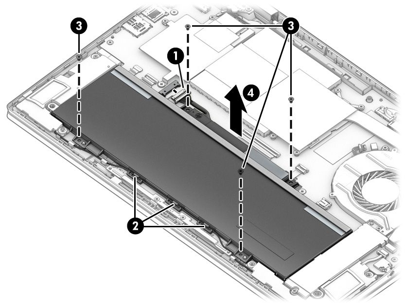
Safety warning notice
       Reduce the possibility of heat-related injuries or of overheating the computer by following the practices
       described.

       WARNING! To reduce the possibility of heat-related injuries or of overheating the computer, do not place
       the computer directly on your lap or obstruct the computer air vents. Use the computer only on a hard, flat
       surface. Do not allow another hard surface, such as an adjoining optional printer, or a soft surface, such as
       pillows or rugs or clothing, to block airflow. Also, do not allow the AC adapter to come into contact with the
       skin or a soft surface, such as pillows or rugs or clothing, during operation. The computer and the AC adapter
       comply with the user-accessible surface temperature limits defined by applicable safety standards.

                                                                                                                        iii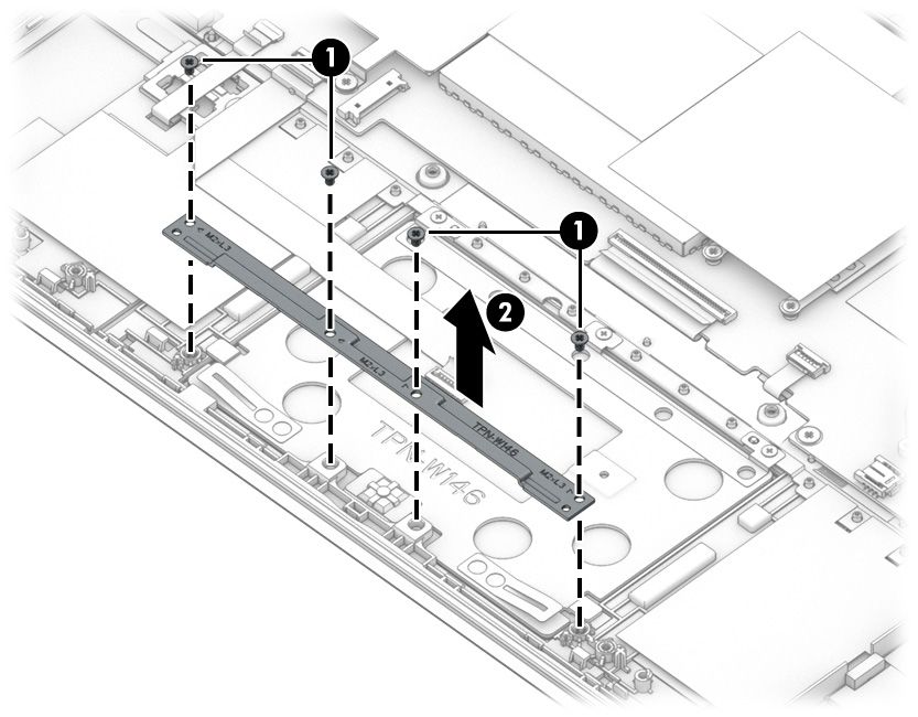
iv Safety warning notice
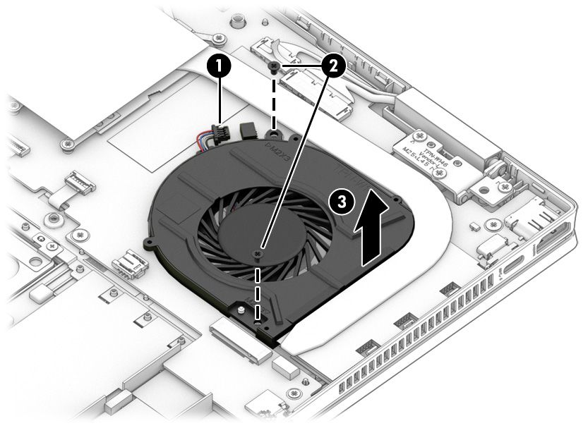
Table of contents

1 Product description ....................................................................................................................................... 1

2 Getting to know your computer ...................................................................................................................... 5
              Right side ............................................................................................................................................................... 5
              Left side ................................................................................................................................................................. 6
              Display .................................................................................................................................................................... 7
                               Low blue light mode (select products only) ........................................................................................ 7
              Keyboard area ........................................................................................................................................................ 8
                               Touchpad settings and components ................................................................................................... 8
                                                 Touchpad settings ............................................................................................................. 8
                                                                   Adjusting touchpad settings .......................................................................... 8
                                                                   Turning on the touchpad ................................................................................ 8
                                                 Touchpad components ...................................................................................................... 9
                               Lights ................................................................................................................................................... 9
                               Button and fingerprint reader ........................................................................................................... 10
                               Special keys ....................................................................................................................................... 11
              Bottom ................................................................................................................................................................. 12
              Labels ................................................................................................................................................................... 13

3 Illustrated parts catalog .............................................................................................................................. 15
              Computer major components .............................................................................................................................. 15
              Display assembly subcomponents ...................................................................................................................... 18
              Miscellaneous parts ............................................................................................................................................. 19

4 Removal and replacement procedures preliminary requirements .................................................................... 21
              Tools required ...................................................................................................................................................... 21
              Service considerations ......................................................................................................................................... 21
                               Plastic parts ....................................................................................................................................... 21
                               Cables and connectors ...................................................................................................................... 21
                               Drive handling ................................................................................................................................... 21
              Electrostatic discharge information .................................................................................................................... 22
                               Generating static electricity .............................................................................................................. 22
                               Preventing electrostatic damage to equipment ............................................................................... 23
                               Personal grounding methods and equipment .................................................................................. 23
                               Grounding the work area ................................................................................................................... 24
                               Recommended materials and equipment ........................................................................................ 24

                                                                                                                                                                                               v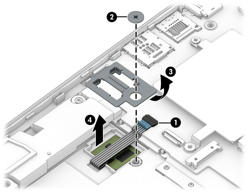
Cleaning your computer ...................................................................................................................................... 25
                                   Enabling HP Easy Clean (select products only) ................................................................................. 25
                                   Removing dirt and debris from your computer ................................................................................ 25
                                   Cleaning your computer with a disinfectant ..................................................................................... 26
                                   Caring for wood veneer (select products only) ................................................................................. 27
                   Packaging and transporting guidelines .............................................................................................................. 27
                   Accessing support information ........................................................................................................................... 27

     5 Removal and replacement procedures for authorized service provider parts .................................................... 29
                   Component replacement procedures .................................................................................................................. 29
                                   Preparation for disassembly ............................................................................................................. 29
                                   Bottom cover and rubber feet ........................................................................................................... 29
                                   Battery ............................................................................................................................................... 31
                                   Solid-state drive ................................................................................................................................ 33
                                   Memory modules ............................................................................................................................... 34
                                   WLAN module .................................................................................................................................... 34
                                   Speakers ............................................................................................................................................ 36
                                   Touchpad ........................................................................................................................................... 37
                                   Fan ..................................................................................................................................................... 38
                                   Heat sink ............................................................................................................................................ 39
                                   Power connector cable ...................................................................................................................... 41
                                   Fingerprint reader ............................................................................................................................. 42
                                   System board .................................................................................................................................... 43
                                   Display assembly ............................................................................................................................... 45
                                   Keyboard with top cover ................................................................................................................... 52

     6 Using Setup Utility (BIOS) ............................................................................................................................. 53
                   Starting Setup Utility (BIOS) ................................................................................................................................ 53
                   Updating Setup Utility (BIOS) .............................................................................................................................. 53
                                   Determining the BIOS version ........................................................................................................... 53
                                   Preparing for a BIOS update .............................................................................................................. 54
                                                    Downloading a BIOS update ........................................................................................... 54
                                                    Installing a BIOS update .................................................................................................. 54

     7 Backing up, restoring, and recovering ........................................................................................................... 56
                   Backing up information and creating recovery media ........................................................................................ 56
                                   Using Windows tools for backing up ................................................................................................. 56
                                   Using the HP Cloud Recovery Download Tool to create recovery media (select products only) ..... 56
                   Restoring and recovering your system ............................................................................................................... 56
                                   Creating a system restore ................................................................................................................. 57

vi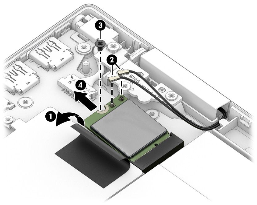
Restoring and recovery methods ...................................................................................................... 57
                               Recovering using HP Recovery media ............................................................................................... 57
                               Changing the computer boot order ................................................................................................... 57
                               Using HP Sure Recover (select products only) .................................................................................. 58

8 Using HP PC Hardware Diagnostics ................................................................................................................ 59
               Using HP PC Hardware Diagnostics Windows (select products only) ................................................................. 59
                               Using an HP PC Hardware Diagnostics Windows hardware failure ID code ...................................... 59
                               Accessing HP PC Hardware Diagnostics Windows ............................................................................ 59
                                               Accessing HP PC Hardware Diagnostics Windows from HP Help and Support
                                               (select products only) ..................................................................................................... 59
                                               Accessing HP PC Hardware Diagnostics Windows from Support Assistant ................... 60
                                               Accessing HP PC Hardware Diagnostics Windows from the Start menu (select
                                               products only) ................................................................................................................. 60
                               Downloading HP PC Hardware Diagnostics Windows ....................................................................... 60
                                               Downloading the latest HP PC Hardware Diagnostics Windows version from HP ......... 60
                                               Downloading the HP PC Hardware Diagnostics Windows from the Microsoft Store ..... 60
                                               Downloading HP Hardware Diagnostics Windows by product name or number
                                               (select products only) ..................................................................................................... 61
                               Installing HP PC Hardware Diagnostics Windows ............................................................................. 61
               Using HP PC Hardware Diagnostics UEFI ............................................................................................................. 61
                               Using an HP PC Hardware Diagnostics UEFI hardware failure ID code ............................................. 61
                               Starting HP PC Hardware Diagnostics UEFI ....................................................................................... 62
                               Downloading HP PC Hardware Diagnostics UEFI to a USB flash drive .............................................. 62
                                               Downloading the latest HP PC Hardware Diagnostics UEFI version .............................. 62
                                               Downloading HP PC Hardware Diagnostics UEFI by product name or number
                                               (select products only) ..................................................................................................... 62
               Using Remote HP PC Hardware Diagnostics UEFI settings (select products only) ............................................. 63
                               Downloading Remote HP PC Hardware Diagnostics UEFI ................................................................. 63
                                               Downloading the latest Remote HP PC Hardware Diagnostics UEFI version ................. 63
                                               Downloading Remote HP PC Hardware Diagnostics UEFI by product name or
                                               number ............................................................................................................................ 63
                               Customizing Remote HP PC Hardware Diagnostics UEFI settings .................................................... 63

9 Specifications .............................................................................................................................................. 65
               Computer specifications ...................................................................................................................................... 65
               35.6 cm (14.0 in) display specifications .............................................................................................................. 65
               Solid-state drive specifications ........................................................................................................................... 66

10 Power cord set requirements ...................................................................................................................... 67
               Requirements for all countries ............................................................................................................................ 67

                                                                                                                                                                                        vii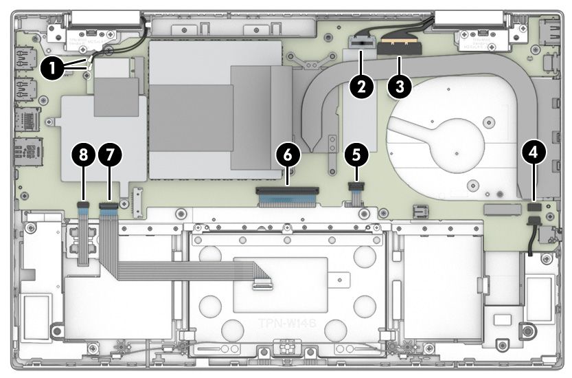
Requirements for specific countries and regions ................................................................................................ 67

   11 Recycling .................................................................................................................................................. 69

   Index ............................................................................................................................................................. 70

viii
1   Product description

    This table provides detailed product information.
    Table 1-1 Product components and their descriptions
    Category             Description

    Product Name         HP Pavilion x360 14 Convertible PC

                         Model number: 14-dy0xxx, 14q-dy0xxx (China/India OLS)

                         CTO Model: 14t-dy000

    Processors           Intel® processors

                         Intel Core™ i7-1165G7 (2.80 GHz base frequency, up to 4.70 GHz with Intel Turbo Boost Technology, 12 MB
                         cache, 4 cores)

                         Intel Core i5-1135G7 (2.40 GHz base frequency, up to 4.20 GHz with Intel Turbo Boost Technology, 8 MB
                         cache, 4 cores)

                         Intel Core i3-1125G4 (2.00 GHz base frequency, up to 3.70 GHz with Intel Turbo Boost Technology, 8 MB
                         cache, 4 cores)

                         Intel Core i3-1115G4 (3.00 GHz base frequency, up to 4.10 GHz with Intel Turbo Boost Technology, 6 MB
                         cache, 2 cores)

                         Intel 7505 Pentium® Gold (2.00 GHz base frequency, up to 3.50 GHz with Intel Turbo Boost Technology, 4 MB
                         cache, 2 cores)

    Graphics             Internal graphics

                         Intel Iris® Xe Graphics (i7/i5 processors)

                         Intel UHD Graphics (i3/Pentium processors)

                         Supports HD Decode, DX12, and HDMI

    Display              35.6 cm (14.0 in), WLED, narrow bezel, eDP 1.2 without PSR, antiglare, 45% NTSC, 250 nits, touch screen

                         Full high definition (FHD) (1920 × 1080), IPS, UWVA

                         High definition (HD) (1366 × 768), SVA

    Memory               Not customer-accessible

                         Up to 16 GB of DDR4-3200 dual-channel support

                         Supports the following configurations:

                         ●    16 GB (8 × 2) or (16 × 1)

                         ●    8 GB (8 × 1 or 4 × 2)

                         ●    4 GB (4 × 1)

    Primary storage      M.2 2280 solid-state drives (NGFF)

                         1 TB, PCIe, value

                         512 GB, PCIe, value

                                                                                                                                     1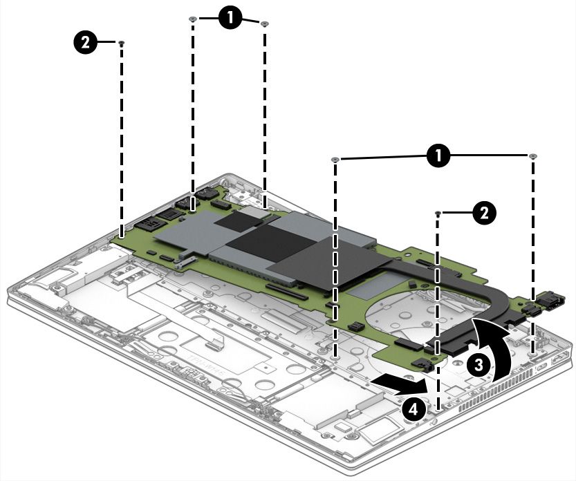
Table 1-1 Product components and their descriptions (continued)
            Category            Description

                                512 GB, PCIe-3 × 2 × 2 + 32 GB Optane™ memory

                                256 GB, PCIe, value

                                256 GB, PCIe-3 × 2 × 2 + 16 GB Optane memory

                                128 GB, PCIe-3 × 4, TLC

            Audio and video     HP Wide Vision HD Camera: indicator LED, USB2.0, HD BSI sensor, f2.0, WDR, 88° WFOV

                                720p by 30 frames per second

                                Dual array digital microphone with appropriate software: beam forming, echo cancellation, and noise
                                suppression

                                Dual speakers

                                Audio brand: B&O

                                Audio control panel: B&O Audio Control

                                Supports speaker swap

                                Supports Cortana (far field)

                                Supports Alexa

                                Supports XiaoWei

            Wireless            Wireless Local Area Network (WLAN) (select products only)

                                Intel Wi-Fi 6 AX201 802.11ax (2 × 2) and Bluetooth® 5 (non-vPro®)

                                Intel Wireless-AC 9461 802.11b/g/n/ac (1 × 1 Bluetooth 5 Combo)

                                Realtek 8852AE-VT Wi-Fi® 6 Bluetooth 5.2 WLAN

                                Compatible with Miracast® devices

                                Supports modern standby (connected)

                                Intel BT Audio Offload

            Card reader         Micro Secure Digital (SD) Media Reader

                                Push-push insertion/removal

            Ports               HDMI 2.0

                                Audio-out (headphone)/audio-in (microphone) combo jack

                                USB 3.2 Gen 2 Type-C (supports power delivery 3.0, data transfer, Display Port 1.4, HDMI 2.0 out, HP Sleep &
                                Charge)

                                (2) USB 3.2 Gen 1 Type-A port

                                AC Smart Pin adapter plug

            Digital pen         HP Pen with cable

            Sensors             Accelerometer + Gyroscope + eCompass

            Keyboard/pointing   Keyboard
            devices
                                Natural silver, island style, 2-coat paint

2   Chapter 1 Product description
Table 1-1 Product components and their descriptions (continued)
Category Description
Natural silver, island style, 3-coat paint, backlit
Spruce blue, island style, 2-coat paint
Spruce blue, island style, 4-coat paint, backlit
Warm gold, island style, 3-coat paint, backlit
Clickpad with image sensor
Power requirements Battery
3 cell, 43 Whr, li polymer
Long life
Fast charge technology
Smart AC adapters
65 W, right angle, 4.5 mm, 1.8 m (6.0 ft)
65 W, right angle, 4.5 mm (LA Merco)
65 W, 4.5 mm, EM
45 W, right angle, 4.5 mm, 1.8 m (6.0 ft)
45 W, right angle, 4.5 mm (LA Merco)
Power cord
C5, 1.0 m (3.3 ft) conventional
Security Trusted Platform Module (TPM) 2.0
Fingerprint reader (select products only)
Operating system Windows® 10 Home 64
Windows 10 Home 64 Chinese Market CPPP
Windows 10 Home 64 High-End Chinese Market CPPP
Windows 10 Home 64 Entry Single Language
Windows 10 Home 64 Plus
Windows 10 Home 64 Plus Single Language
Windows 10 Home 64 Plus Single Language Africa Market PPP
Windows 10 Home 64 Plus Single Language APAC EM PPP
Windows 10 Home 64 Plus Single Language India Market PPP
Windows 10 Home 64 Plus Single Language Indonesia Market PPP
Windows 10 Home 64 Single Language
Windows 10 Home 64 Single Language Africa Market PPP
Windows 10 Home 64 Single Language APAC Market PPP
Windows 10 Home 64 Single Language India Market PPP
3Table 1-1 Product components and their descriptions (continued)
Category Description
Windows 10 Home 64 Single Language Indonesia Market PPP
Windows 10 Home 64 Single Language Entry Africa Market PPP
Windows 10 Home 64 Single Language Entry APAC EM PPP
Windows 10 Home 64 Single Language Entry India Market PPP
Windows 10 Home 64 Single Language Entry Indonesia Market PPP
Windows 10 Home 64 Single Language Value Africa Market PPP
Windows 10 Home 64 Single Language Value APAC Market PPP
Windows 10 Home 64 Single Language Value India Market PPP
Windows 10 Home 64 Single Language Value Indonesia Market PPP
Windows 10 Home 64 Value Single Language
Windows 10 Home S 64
Windows 10 Home S 64 Entry
Windows 10 Home S 64 Entry Single Language
Windows 10 Home S 64 Plus
Windows 10 Home S 64 Single Language
Windows 10 Home S 64 Value
Windows 10 Home S 64 Value Single Language
Windows 10 Pro 64
FreeDOS 3.0
Serviceability End user replaceable parts
AC adapter
4 Chapter 1 Product description2 Getting to know your computer
Your computer features top-rated components. This chapter provides details about your components, where
they are located, and how they work.
Right side
Identify the components on the right side of the computer.
Table 2-1 Right-side components and their descriptions
Component Description
(1) Speaker Produces sound.
(2) microSD™ memory card reader Reads optional memory cards that enable you to store, manage,
share, or access information.
To insert a card:
1. Hold the card label-side up, with connectors facing the
computer.
2. Insert the card into the memory card reader, and then
press in on the card until it is firmly seated.
To remove a card:
▲ Press in on the card, and then remove it from the memory
card reader.
(3) USB SuperSpeed ports (2) Connect a USB device, provide high-speed data transfer, and (for
select products) charge small devices (such as a smartphone)
when the computer is on or in Sleep mode.
NOTE: Use a standard USB Type-A charging cable or cable
adapter (purchased separately) when charging a small external
device.
(4) AC adapter and battery light ● White: The AC adapter is connected and the battery is fully
charged.
● Blinking amber: The AC adapter is disconnected and the
battery has reached a low battery level.
● Amber: The AC adapter is connected and the battery is
charging.
5Table 2-1 Right-side components and their descriptions (continued)
Component Description
● Off: The battery is not charging.
(5) Power connector Connects an AC adapter.
Left side
Identify the components on the left side of the computer.
Table 2-2 Left-side components and their descriptions
Component Description
(1) HDMI port Connects an optional video or audio device, such as a high-
definition television, any compatible digital or audio component,
or a high-speed High-Definition Multimedia Interface (HDMI)
device.
(2) USB Type-C® power connector and SuperSpeed Connects an AC adapter that has a USB Type-C connector,
port supplying power to the computer and, if needed, charging the
computer battery.
– and –
Connects a USB device, provides high-speed data transfer, and
(for select products) charges small devices (such as a
smartphone) when the computer is on or in Sleep mode.
NOTE: Use a standard USB Type-C charging cable or cable
adapter (purchased separately) when charging a small external
device.
– and –
Connects a display device that has a USB Type-C connector,
providing DisplayPort™ output.
(3) Vent Enables airflow to cool internal components.
NOTE: The computer fan starts up automatically to cool
internal components and prevent overheating. It is normal for
the internal fan to cycle on and off during routine operation.
(4) Audio-out (headphone)/Audio-in (microphone) Connects optional powered stereo speakers, headphones,
combo jack earbuds, a headset, or a television audio cable. Also connects an
optional headset microphone. This jack does not support
optional standalone microphones.
6 Chapter 2 Getting to know your computerTable 2-2 Left-side components and their descriptions (continued)
Component Description
WARNING! To reduce the risk of personal injury, adjust the
volume before putting on headphones, earbuds, or a headset.
For additional safety information, see the Regulatory, Safety,
and Environmental Notices.
To access this guide:
▲ Type HP Documentation in the taskbar search box,
and then select HP Documentation.
NOTE: When a device is connected to the jack, the computer
speakers are disabled.
(5) Speaker Produces sound.
Display
The computer display can include essential components such as speakers, antennas, cameras, and
microphones.
Low blue light mode (select products only)
Your computer display is shipped from the factory in low blue light mode for improved eye comfort and
safety. Also, blue light mode automatically adjusts blue light emissions when you are using the computer at
night or for reading.
WARNING! To reduce the risk of serious injury, read the Safety & Comfort Guide. It describes proper
workstation setup and proper posture, health, and work habits for computer users. The Safety & Comfort
Guide also provides important electrical and mechanical safety information. The Safety & Comfort Guide is
available on the web at http://www.hp.com/ergo.
Display 7Table 2-3 Display components and their descriptions
Component Description
(1) Internal microphones (2) Record sound.
(2) Camera Allows you to video chat, record video, and record still images. Some
cameras also allow a facial recognition logon to Windows, instead of
a password logon.
NOTE: Camera functions vary depending on the camera hardware
and software installed on your product.
(3) Camera light On: The camera is in use.
(4) WLAN antennas* Send and receive wireless signals to communicate with wireless local
area networks (WLANs).
*The antennas are not visible from the outside of the computer. For optimal transmission, keep the areas immediately around the
antennas free from obstructions.
For wireless regulatory notices, see the section of the Regulatory, Safety, and Environmental Notices that applies to your country or
region.
To access this guide:
▲ Type HP Documentation in the taskbar search box, and then select HP Documentation.
Keyboard area
Keyboards can vary by language.
Touchpad settings and components
Learn the touchpad settings and components
Touchpad settings
Learn how to adjust touchpad settings.
Adjusting touchpad settings
Use these steps to adjust touchpad settings and gestures.
1. Type touchpad settings in the taskbar search box, and then press enter.
2. Choose a setting.
Turning on the touchpad
Follow these steps to turn on the touchpad.
1. Type touchpad settings in the taskbar search box, and then press enter.
2. Using an external mouse, click the touchpad button.
If you are not using an external mouse, press the Tab key repeatedly until the pointer rests on the
touchpad button. Then press the spacebar to select the button.
8 Chapter 2 Getting to know your computerTouchpad components
Identify the touchpad components.
Table 2-4 Touchpad components and their descriptions
Component Description
(1) Touchpad zone Reads your finger gestures to move the pointer or activate items
on the screen.
(2) Left control zone Textured area that allows you to perform additional gestures.
(3) Right control zone Textured area that allows you to perform additional gestures.
Lights
Identify the lights on the computer.
Keyboard area 9Table 2-5 Lights and their descriptions
Component Description
(1) Caps lock light On: Caps lock is on, which switches the key input to all capital
letters.
(2) Mute light ● On: Computer sound is off.
● Off: Computer sound is on.
(3) Power light ● On: The computer is on.
● Blinking (select products only): The computer is in the
Sleep state, a power-saving state. The computer shuts off
power to the display and other unnecessary components.
● Off: Depending on your computer model, the computer is
off, in Hibernation, or in Sleep. Hibernation is the power-
saving state that uses the least amount of power.
Button and fingerprint reader
Identify the computer button and fingerprint reader.
Fingerprint readers, which enable a fingerprint logon, can be located on the touchpad, on a side panel of the
computer, or on the top cover below the keyboard.
IMPORTANT: To verify that your computer supports fingerprint reader sign-in, type Sign-in options in
the taskbar search box and follow the on-screen instructions. If Fingerprint reader is not listed as an option,
then your computer does not include a fingerprint reader.
Table 2-6 Button and fingerprint reader and their descriptions
Component Description
(1) Power button ● When the computer is off, press the button briefly to turn
on the computer.
10 Chapter 2 Getting to know your computerTable 2-6 Button and fingerprint reader and their descriptions (continued)
Component Description
● When the computer is on, press the button briefly to
initiate Sleep.
● When the computer is in the Sleep state, press the button
briefly to exit Sleep (select products only).
● When the computer is in Hibernation, press the button
briefly to exit Hibernation.
IMPORTANT: Pressing and holding down the power button
results in the loss of unsaved information.
If the computer has stopped responding and shutdown
procedures are ineffective, press and hold the power button
down for at least 10 seconds to turn off the computer.
To learn more about your power settings, see your power
options:
▲ Right-click the Power icon , and then select Power
Options.
(2) Fingerprint reader (select products only) Allows a fingerprint logon to Windows, instead of a password
logon.
▲ Swipe down across the fingerprint reader.
IMPORTANT: To prevent fingerprint logon issues, be sure
when you register your fingerprint that all sides of your
finger are registered by the fingerprint reader.
Special keys
Identify the special keys.
Table 2-7 Special keys and their descriptions
Component Description
(1) esc key Displays system information when pressed in combination with
the fn key.
Keyboard area 11Table 2-7 Special keys and their descriptions (continued)
Component Description
(2) fn key Executes specific functions when pressed in combination with
another key.
(3) Windows key Opens the Start menu.
NOTE: Pressing the Windows key again will close the Start
menu.
(4) Action keys Execute frequently used system functions as defined by the icon
symbols on f1 through f12 function keys.
(5) Power button ● When the computer is off, press the button briefly to turn
on the computer.
● When the computer is on, press the button briefly to
initiate Sleep.
● When the computer is in the Sleep state, press the button
briefly to exit Sleep (select products only).
● When the computer is in Hibernation, press the button
briefly to exit Hibernation.
IMPORTANT: Pressing and holding down the power button
results in the loss of unsaved information.
If the computer has stopped responding and shutdown
procedures are ineffective, press and hold the power button
down for at least 10 seconds to turn off the computer.
To learn more about your power settings, see your power
options:
▲ Right-click the Power icon , and then select Power
Options.
Bottom
Identify the bottom components.
12 Chapter 2 Getting to know your computerTable 2-8 Bottom components and their descriptions
Component Description
(1) Speakers (2) Produce sound.
(2) Vent Enables airflow to cool internal components.
NOTE: The computer fan starts up automatically to cool
internal components and prevent overheating. It is normal
for the internal fan to cycle on and off during routine
operation.
Labels
The labels affixed to the computer provide information that you might need when you troubleshoot system
problems or travel internationally with the computer. Labels can be in paper form or imprinted on the product.
IMPORTANT: Check the following locations for the labels described in this section: the bottom of the
computer, inside the battery bay, under the service door, on the back of the display, or on the bottom of a
tablet kickstand.
● Service label—Provides important information to identify your computer. When contacting support, you
might be asked for the serial number, the product number, or the model number. Locate this
information before you contact support.
Your service label will resemble one of the following examples. Refer to the illustration that most closely
matches the service label on your computer.
Labels 13Table 2-9 Service label components
Component
(1) HP product name
(2) Model number
(3) Warranty period
(4) Product ID
(5) Serial number
Table 2-10 Service label components
Component
(1) HP product name
(2) Product ID
(3) Serial number
(4) Warranty period
● Regulatory label(s)—Provide(s) regulatory information about the computer.
● Wireless certification label(s)—Provide(s) information about optional wireless devices and the approval
markings for the countries or regions in which the devices have been approved for use.
14 Chapter 2 Getting to know your computer3 Illustrated parts catalog
Use this table to determine the spare parts that are available for the computer.
Computer major components
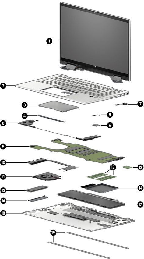
To identify the computer major components, use this illustration and table.
NOTE: HP continually improves and changes product parts. For complete and current information about
supported parts for your computer, go to http://partsurfer.hp.com, select your country or region, and then
follow the on-screen instructions.
NOTE: Details about your computer, including model, serial number, product key, and length of warranty,
are on the service tag at the bottom of your computer.
Computer major components 15Table 3-1 Computer major component descriptions and part numbers
Item Component Spare part number
(1) Display assembly not available as a spare part
NOTE: Display spare parts are available only as subcomponents.
(2) Top cover/keyboard
Fingerprint reader, backlit, natural silver M45219-xx1
No fingerprint reader, backlit, natural silver M45220-xx1
Fingerprint reader, backlit, natural silver aluminum M45221-xx1
No fingerprint reader, backlit, natural silver aluminum M45222-xx1
Fingerprint reader, backlit, warm gold aluminum M45223-xx1
Fingerprint reader, natural silver M45224-xx1
No fingerprint reader, natural silver M45225-xx1
No fingerprint reader, spruce blue M45228-xx1
No fingerprint reader, spruce blue, backlit M45229-xx1
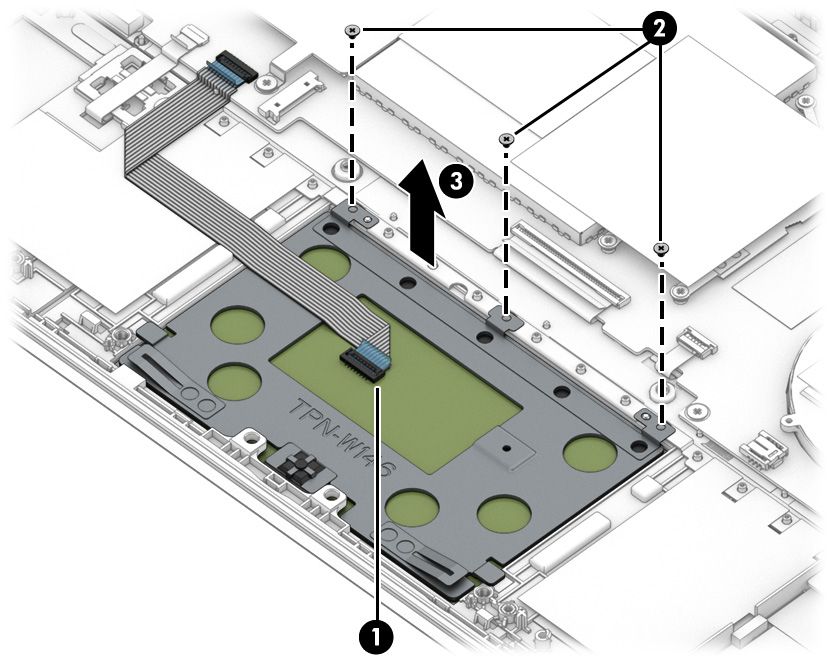
(3) Touchpad
NOTE: The touchpad cable is available as spare part number M45019-001.
Spruce blue M45009-001
Natural silver M45010-001
Warm gold M45011-001
(4) Touchpad bracket not available as a spare part
(5) Fingerprint reader M36397-001
NOTE: The fingerprint reader cable is available in the Cable Kit as spare part number
M45020-001.
Natural silver M45007-001
Warm gold M49762-001
(6) Fingerprint reader bracket not available as a spare part
(7) Power connector cable M45022-001
(8) Speakers (left and right) M45029-001
(9) System board (includes integrated processor)
NOTE: All system board spare part kits include replacement thermal material.
All system boards use the following part numbers:
xxxxxx-001: Non-Windows operating systems
xxxxxx-601: Windows operating system
Intel Core i7-1165G7 M45033-xx1
Intel Core i5-1135G7 M45032-xx1
Intel Core i3-1125G4 M45749-xx1
16 Chapter 3 Illustrated parts catalogTable 3-1 Computer major component descriptions and part numbers (continued)
Item Component Spare part number
Intel Core i3-1115G4 M45031-xx1
Intel Pentium Gold 7505 M45034-xx1
(10) Heat sink (includes replacement thermal material) M45023-001
(11) Fan M45024-001
(12) WLAN module
Intel Wi-Fi 6 AX201 802.11ax (2 × 2) and Bluetooth 5 (non-vPro) L92724-005
Intel Wireless-AC 9461 802.11ac 1 × 1 Wi-Fi + Bluetooth 5 L25889-005
Realtek Wi-Fi 6 RTL8852AE-VT + Bluetooth 5.2 M34029-005
(13) Memory modules (DDR4, PC-3200)
16 GB L67710-005
8 GB L46598-005
4 GB L83673-005
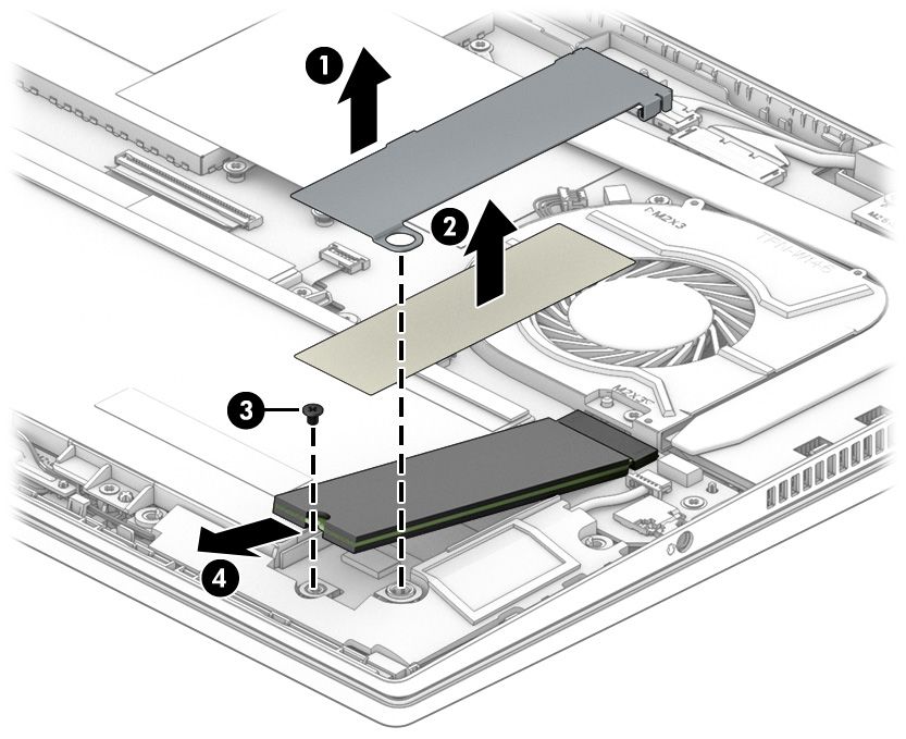
(14) Solid-state drive cover not available as a spare part
(15) Solid-state drive (PCIe)
NOTE: The thermal pad for use with solid-state drives are available as spare part
number M45025-001.
1 TB L85370-005
512 GB L85364-005
512 GB, PCIe + 32 GB Optane memory L85366-005
256 GB, PCIe L85354-005
256 GB, PCIe + 16 GB Optane memory L85356-005
128 GB, PCIe, TLC M06792-005
(16) Solid-state drive cover not available as a spare part
(17) Battery (3 cell, 43 Whr) M24648-007
(18) Bottom cover
Ash gray M45015-001
Natural silver, aluminum M51582-001
Natural silver M45016-001
Warm gold M45017-001
(19) Rubber feet
Ash gray M45026-001
Natural silver M45027-001
Warm gold M45028-001
Computer major components 17Display assembly subcomponents
To identify the display assembly subcomponents, use this illustration and table.
Table 3-2 Display component descriptions and part numbers
Item Component Spare part number
(1) Display panel
HD M45012-001
FHD M45013-001
(2) Display/touch control board not available as a
spare part
(3) Display/touch control board cable M45021-001
(4) Camera module M45014-001
(5) Camera cable M45018-001
(6) WLAN antennas and cables M44997-001
(7) Hinges (left and right) M07104-001
FHD models M45005-001
HD models M45006-001
(8) Hinge cover
FHD models M45003-001
HD models M45004-001
(9) Display back cover
Natural silver, HD panel M44998-001
18 Chapter 3 Illustrated parts catalogTable 3-2 Display component descriptions and part numbers (continued)
Item Component Spare part number
Spruce blue, HD panel M44999-001
Natural silver, FHD panel M45000-001
Warm gold, FHD panel M45001-001
Spruce blue, FHD panel M45002-001
Miscellaneous parts
To identify the miscellaneous parts, use this table.
Table 3-3 Miscellaneous part descriptions and part numbers
Component Spare part number
AC adapters
65 W, nPFC, SMART, 3 pin, 4.5 mm 710412-001
65 W, nPFC, SMART, 3 pin, 4.5 mm, EM 913691-850
45 W, nPFC, SMART, RC, 4.5 mm, nonslim 741727-001
Protective Tape Kit (includes left system board protective tape, right system board protective tape, and M45230-001
memory protective tape; these are not the metal covers)
Screw Kit M45030-001
Active pen, Sunwoda 910942-001
Pen tip, Sunwoda L04536-001
Zenvo Pen with cable L95614-001
Adapters
HDMI-to-VGA adapter 701943-001
USB-to-Gigabit RJ-45 adapter 829941-001
USB-C-to-RJ-45 adapter 855560-001
USB-C-to-HDMI 2.0 adapter 935325-001
USB-C-to-USB-A adapter 914936-001
Power cord (C5, conventional, 1.0 m [3.3 ft])
Argentina L19357-001
Australia L19358-001
Brazil L19359-001
Denmark L19360-001
Europe (Austria, Belgium, Finland, France, Germany, the Netherlands, Norway, and Sweden) L19361-001
India L19363-001
Israel L19362-001
Miscellaneous parts 19Table 3-3 Miscellaneous part descriptions and part numbers (continued)
Component Spare part number
Italy L19364-001
Japan L19365-001
North America L19367-001
People's Republic of China L19368-001
South Africa L19369-001
South Korea L19366-001
Switzerland L19370-001
Taiwan L19372-001
Thailand L19371-001
The United Kingdom L19373-001
20 Chapter 3 Illustrated parts catalog4 Removal and replacement procedures
preliminary requirements
Use this information to properly prepare to disassemble and reassemble the computer.
Tools required
You need the following tools to complete the removal and replacement procedures:
● Nonconductive, nonmarking pry tool
● Magnetic Phillips P1 screwdriver
Service considerations
The following sections include some of the considerations that you must keep in mind during disassembly
and assembly procedures.
NOTE: As you remove each subassembly from the computer, place the subassembly (and all accompanying
screws) away from the work area to prevent damage.
Plastic parts
Using excessive force during disassembly and reassembly can damage plastic parts.
Cables and connectors
Handle cables with extreme care to avoid damage.
IMPORTANT: When servicing the computer, be sure that cables are placed in their proper locations during
the reassembly process. Improper cable placement can damage the computer.
Apply only the tension required to unseat or seat the cables during removal and insertion. Handle cables by
the connector whenever possible. In all cases, avoid bending, twisting, or tearing cables. Be sure that cables
are routed so that they cannot be caught or snagged as you remove or replace parts. Handle flex cables with
extreme care; these cables tear easily.
Drive handling
Note the following guidelines when handling drives.
Tools required 21IMPORTANT: Drives are fragile components. Handle them with care. To prevent damage to the computer,
damage to a drive, or loss of information, observe these precautions:
Before removing or inserting a hard drive, shut down the computer. If you are unsure whether the computer is
off or in Hibernation, turn the computer on, and then shut it down through the operating system.
Before handling a drive, be sure that you are discharged of static electricity. While handling a drive, avoid
touching the connector.
Before removing an optical drive, be sure that a disc is not in the drive, and be sure that the optical drive tray
is closed.
Handle drives on surfaces covered with at least 2.54 cm (1 inch) of shock-proof foam.
Avoid dropping drives from any height onto any surface.
After removing a hard drive or an optical drive, place it in a static-proof bag.
Avoid exposing an internal hard drive to products that have magnetic fields, such as monitors or speakers.
Avoid exposing a drive to temperature extremes or liquids.
If a drive must be mailed, place the drive in a bubble pack mailer or other suitable form of protective
packaging, and label the package “FRAGILE.”
Electrostatic discharge information
A sudden discharge of static electricity from your finger or other conductor can destroy static-sensitive
devices or microcircuitry. Often the spark is neither felt nor heard, but damage occurs. An electronic device
exposed to electrostatic discharge (ESD) might not appear to be affected at all and can work perfectly
throughout a normal cycle. The device might function normally for a while, but it has been degraded in the
internal layers, reducing its life expectancy.
Networks built into many integrated circuits provide some protection, but in many cases, the discharge
contains enough power to alter device parameters or melt silicon junctions.
IMPORTANT: To prevent damage to the device when you remove or install internal components, observe
these precautions:
Keep components in their electrostatic-safe containers until you are ready to install them.
Before touching an electronic component, discharge static electricity by using the guidelines described
Personal grounding methods and equipment on page 23.
Avoid touching pins, leads, and circuitry. Handle electronic components as little as possible.
If you remove a component, place it in an electrostatic-safe container.
Generating static electricity
Follow these static electricity guidelines.
● Different activities generate different amounts of static electricity.
● Static electricity increases as humidity decreases.
Table 4-1 Static electricity occurrence based on activity and humidity
Relative humidity
Event 55% 40% 10%
Walking across carpet 7,500 V 15,000 V 35,000 V
22 Chapter 4 Removal and replacement procedures preliminary requirementsTable 4-1 Static electricity occurrence based on activity and humidity (continued)
Relative humidity
Walking across vinyl floor 3,000 V 5,000 V 12,000 V
Motions of bench worker 400 V 800 V 6,000 V
Removing DIPs (dual in-line packages) from plastic tube 400 V 700 V 2,000 V
Removing DIPs from vinyl tray 2,000 V 4,000 V 11,500 V
Removing DIPs from polystyrene foam 3,500 V 5,000 V 14,500 V
Removing bubble pack from PCB (printed circuit board) 7,000 V 20,000 V 26,500 V
Packing PCBs in foam-lined box 5,000 V 11,000 V 21,000 V
Multiple electric components can be packaged together in plastic tubes, trays, or polystyrene foam.
NOTE: As little as 700 V can degrade a product.
Preventing electrostatic damage to equipment
Many electronic components are sensitive to ESD. Circuitry design and structure determine the degree of
sensitivity. The following packaging and grounding precautions are necessary to prevent static electricity
damage to electronic components.
● To avoid hand contact, transport products in static-safe containers such as tubes, bags, or boxes.
● Protect all electrostatic parts and assemblies with conductive or approved containers or packaging.
● Keep electrostatic-sensitive parts in their containers until they arrive at static-free stations.
● Place items on a grounded surface before removing them from their container.
● Always be properly grounded when touching a sensitive component or assembly.
● Avoid contact with pins, leads, or circuitry.
● Place reusable electrostatic-sensitive parts from assemblies in protective packaging or conductive
foam.
Personal grounding methods and equipment
Using certain equipment can prevent static electricity damage to electronic components.
● Wrist straps are flexible straps with a maximum of 1 MΩ ±10% resistance in the ground cords. To
provide proper ground, a strap must be worn snug against bare skin. The ground cord must be
connected and fit snugly into the banana plug connector on the grounding mat or workstation.
● Heel straps/Toe straps/Boot straps can be used at standing workstations and are compatible with
most types of shoes or boots. On conductive floors or dissipative floor mats, use them on both feet with
a maximum of 1 MΩ ±10% resistance between the operator and ground.
Table 4-2 Static shielding protection levels
Static shielding protection levels
Method Voltage
Antistatic plastic 1,500
Electrostatic discharge information 23Table 4-2 Static shielding protection levels (continued)
Static shielding protection levels
Carbon-loaded plastic 7,500
Metallized laminate 15,000
Grounding the work area
To prevent static damage at the work area, follow these precautions.
● Cover the work surface with approved static-dissipative material.
● Use a wrist strap connected to a properly grounded work surface and use properly grounded tools and
equipment.
● Use static-dissipative mats, foot straps, or air ionizers to give added protection.
● Handle electrostatic sensitive components, parts, and assemblies by the case or PCB laminate. Handle
them only at static-free work areas.
● Turn off power and input signals before inserting and removing connectors or test equipment.
● Use fixtures made of static-safe materials when fixtures must directly contact dissipative surfaces.
● Keep the work area free of nonconductive materials, such as ordinary plastic assembly aids and
polystyrene foam.
● Use conductive field service tools, such as cutters, screwdrivers, and vacuums.
● Avoid contact with pins, leads, or circuitry.
Recommended materials and equipment
HP recommends certain materials and equipment to prevent static electricity.
● Antistatic tape
● Antistatic smocks, aprons, or sleeve protectors
● Conductive bins and other assembly or soldering aids
● Conductive foam
● Conductive tabletop workstations with ground cord of 1 MΩ ±10% resistance
● Static-dissipative table or floor mats with hard tie to ground
● Field service kits
● Static awareness labels
● Wrist straps and footwear straps providing 1 MΩ ±10% resistance
● Material handling packages
● Conductive plastic bags
● Conductive plastic tubes
● Conductive tote boxes
● Opaque shielding bags
24 Chapter 4 Removal and replacement procedures preliminary requirements● Transparent metallized shielding bags
● Transparent shielding tubes
Cleaning your computer
Cleaning your computer regularly removes dirt and debris so that your device continues to operate at its best.
Use the following information to safely clean the external surfaces of your computer.
Enabling HP Easy Clean (select products only)
HP Easy Clean helps you to avoid accidental input while you clean the computer surfaces. This software
disables devices such as the keyboard, touch screen, and touchpad for a preset amount of time so that you
can clean all computer surfaces.
1. Start HP Easy Clean in one of the following ways:
● Select the Start menu, and then select HP Easy Clean.
– or –
● Select the HP Easy Clean icon in the taskbar.
– or –
● Select Start, and then select the HP Easy Clean tile.
2. Now that your device is disabled for a short period, see Removing dirt and debris from your computer
on page 25 for the recommended steps to clean the high-touch, external surfaces on your computer.
After you remove the dirt and debris, you can also clean the surfaces with a disinfectant. See Cleaning
your computer with a disinfectant on page 26 for guidelines to help prevent the spread of harmful
bacteria and viruses.
Removing dirt and debris from your computer
Here are the recommended steps to clean dirt and debris from your computer.
For computers with wood veneer, see Caring for wood veneer (select products only) on page 27.
1. Wear disposable gloves made of latex (or nitrile gloves, if you are latex-sensitive) when cleaning the
surfaces.
2. Turn off your device and unplug the power cord and other connected external devices. Remove any
installed batteries from items such as wireless keyboards.
CAUTION: To prevent electric shock or damage to components, never clean a product while it is turned
on or plugged in.
3. Moisten a microfiber cloth with water. The cloth should be moist, but not dripping wet.
IMPORTANT: To avoid damaging the surface, avoid abrasive cloths, towels, and paper towels.
4. Wipe the exterior of the product gently with the moistened cloth.
IMPORTANT: Keep liquids away from the product. Avoid getting moisture in any openings. If liquid
makes its way inside your HP product, it can cause damage to the product. Do not spray liquids directly
on the product. Do not use aerosol sprays, solvents, abrasives, or cleaners containing hydrogen
peroxide or bleach that might damage the finish.
Cleaning your computer 255. Start with the display (if applicable). Wipe carefully in one direction, and move from the top of the
display to the bottom. Finish with any flexible cables, like power cord, keyboard cable, and USB cables.
6. Be sure that surfaces have completely air-dried before turning the device on after cleaning.
7. Discard the gloves after each cleaning. Clean your hands immediately after you remove the gloves.
See Cleaning your computer with a disinfectant on page 26 for recommended steps to clean the high-touch,
external surfaces on your computer to help prevent the spread of harmful bacteria and viruses.
Cleaning your computer with a disinfectant
The World Health Organization (WHO) recommends cleaning surfaces, followed by disinfection, as a best
practice for preventing the spread of viral respiratory illnesses and harmful bacteria.
After cleaning the external surfaces of your computer using the steps in Removing dirt and debris from your
computer on page 25, Caring for wood veneer (select products only) on page 27, or both, you might also
choose to clean the surfaces with a disinfectant. A disinfectant that is within HP’s cleaning guidelines is an
alcohol solution consisting of 70% isopropyl alcohol and 30% water. This solution is also known as rubbing
alcohol and is sold in most stores.
Follow these steps when disinfecting high-touch, external surfaces on your computer:
1. Wear disposable gloves made of latex (or nitrile gloves, if you are latex-sensitive) when cleaning the
surfaces.
2. Turn off your device and unplug the power cord and other connected external devices. Remove any
installed batteries from items such as wireless keyboards.
CAUTION: To prevent electric shock or damage to components, never clean a product while it is turned
on or plugged in.
3. Moisten a microfiber cloth with a mixture of 70% isopropyl alcohol and 30% water. The cloth should be
moist, but not dripping wet.
CAUTION: Do not use any of the following chemicals or any solutions that contain them, including
spray-based surface cleaners: bleach, peroxides (including hydrogen peroxide), acetone, ammonia, ethyl
alcohol, methylene chloride, or any petroleum-based materials, such as gasoline, paint thinner,
benzene, or toluene.
IMPORTANT: To avoid damaging the surface, avoid abrasive cloths, towels, and paper towels.
4. Wipe the exterior of the product gently with the moistened cloth.
IMPORTANT: Keep liquids away from the product. Avoid getting moisture in any openings. If liquid
makes its way inside your HP product, it can cause damage to the product. Do not spray liquids directly
on the product. Do not use aerosol sprays, solvents, abrasives, or cleaners containing hydrogen
peroxide or bleach that might damage the finish.
5. Start with the display (if applicable). Wipe carefully in one direction, and move from the top of the
display to the bottom. Finish with any flexible cables, like power cord, keyboard cable, and USB cables.
6. Be sure that surfaces have completely air-dried before turning the device on after cleaning.
7. Discard the gloves after each cleaning. Clean your hands immediately after you remove the gloves.
26 Chapter 4 Removal and replacement procedures preliminary requirementsYou can also read