Volo Planning Guide January 2021 - Trendway
←
→
Page content transcription
If your browser does not render page correctly, please read the page content below
Volo          ®

Planning Guide

      January 2021
Contents
Your Vision, Your Volo................................................................................. 3
Seven steps to specification......................................................................3
Design and Installation Planning............................................................. 4
Volo Movable Walls Elements....................................................... 10 - 25
      Components............................................................................. 10 - 17
      Crown and Base Styles...................................................................11
      Panel Frames.....................................................................................12
      Sliding Door Sections............................................................13 - 17
        Frameless Glass Section ..........................................................14
        Single Aluminum Framed Section .......................................15
        Double Aluminum Framed Section .....................................16
              Single Wood Door Section .....................................................17
       Double Wood Door Section ..................................................18
       Sliding Door Dimensions.......................................................... 19
     Swing Door Frame.................................................................20 - 21
     Doors/Door Hardware.........................................................22 - 26
     Tiles.............................................................................................27 - 29
Connectors.......................................................................................... 30 - 36
     Horizontal Connectors........................................................ 30 - 31
     Vertical Connectors..............................................................32 - 33
     Wall Starts.........................................................................................32
     End of Run Connectors................................................................33
     Inline Connectors........................................................................... 34
     Condition Connectors .................................................................35
     Volo to Clear Wall and TrendWall Connectors.................... 36
Power and Data..................................................................................37 - 43
     8 Wire System................................................................................. 37
     Accessing Building Power ........................................................37
       Vertical Power/Data Routing ..................................................37
       Horizontal Power/Data Routing ...................................38 - 40
       Power Specification – Steps and Calculations............41 - 43
Acoustics .............................................................................................44 - 45
Installation Overview....................................................................... 46 - 54
Frequently Asked Questions........................................................ 55 - 56

               Volo Planning Guide                           2
Volo® Movable Wall

Your Vision, Your Volo®!
What's your perfect space? Whatever your vision, Volo brings it to life with speed, ease and
practicality.

Volo Movable Wall is a unitized, non-progressive panel system that is quick to specify, install
and reconfigure. Volo is designed and planned like a frame and tile system, but panels ship
unitized and ready to install.

Volo offers a creative range of surface material options for varying degrees of privacy and
function. Volo can create the aesthetic of fine custom millwork, or the simple functionality of
drywall construction. Plus, the versatile panel sizing conforms to any space dimension require-
ments. Personalizing Volo Walls couldn’t be easier.

NOTE: The digital AP binder includes the marketing and technical documents you need to
sell, specify, and respond to customer requests for documentation. Dealers and customers can
download it from the Documents portion of Design Resources. See details in the FAQ section,
page 49.

Seven steps to specs:

1. Pre-qualify the project

2. Select Crown and Base styles

3. Select the Panel Frame style to match the Crown and Base style

4. Select Tile sizes, materials and specify tile positions on the frame

5. Select Sliding or Swing Door style and Door Hardware

6. Specify Frame Condition Connectors

7. Specify Electrical and Data components

                     Volo Planning Guide         3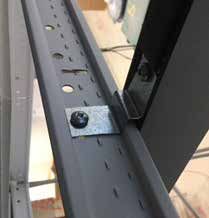
Design and Installation Planning
Proper planning and preparation is key to successful and profitable Volo projects. Take the
time to fully understand the customer’s needs and requirements.

IMPORTANT: Use the Project File tool to pre-qualify the project and select the product that
suits the client's price parameters. Have their Request for Bid documentation on hand when
performing site surveys and during design and installation. It is critical to document all deci-
sions made from start to finish.

Trendway field support
Trendway offers Field Technical Support for a nominal fee. Approved Trendway Technicians can
take field measurements, train and assist during the actual installation at the customer location.
Using this resource assures accurate product design and planning, as well as fast, expert instal-
lation. Contact the Trendway Architectural Product team or Field Technical Support team for
more details.

NOTE: When planning for a Volo application that is not attached to a ceiling, the Freestanding
Volo Kit contains the parts needed to effectively provide the additional structural integrity
required for freestanding capability. Order part number VFCK for the kit of parts. This method
adds the rigidity necessary for a freestanding wall up to a 12' run. If you desire other dimen-
sions, contact your Trendway Architectural Specialist and design team for help.

                                                                        Freestanding Volo applications
                                                                        require the Volo Freestanding
                                                                        Crown Kit (VFCK),
                                                                        Important: Reveal Wall Starts
                                                                        and wall-hung components
                                                                        CAN NOT be installed on
                                                                        freestanding applications.

                                                                        NOTE: Panels must be
                                                                        securely braced during
                                                                        installation of Volo
                                                                        freestanding applications.
                                                                        Please refer to instruction
                                                                        sheet INS659 for proper
                                                                        installation sequence.

                    Volo Planning Guide         4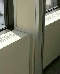
Site survey and verified field measurements
• A thorough pre-installation survey is required.

• Ensures fast, accurate, effective space planning and design.

• Allows effective scheduling for timely completion, no lost time on the job.

• Improves profit through problem-free installations, happy customers and return business.

Floor plans
• Accurate floor plans with key dimensions and conditions within the building architecture are es-
 sential. They should include:
 a. Overall space dimensions
 b. Wall locations and distance from columns
 c. Wall runs that terminate flush with building wall surfaces

• Door locations for ceiling height measurements are crucial for accuracy — door frames offer
 just ± 1/2" of adjustment, and Full Height Doors are limited to 1/4" of adjustment.

• Define the location of the partition run. Volo Vertical Connectors are 2-1/2" thick, so using con-
 struction lines that are offset by 1-1/4" is a good place to start (center of panel). The thickness
 of a panel varies depending on the tiles used, but Wall Starts and condition connectors are
 consistently 2-1/2" thick.

• Once the desired location of the walls is determined, you can begin the office layout.

• The framing layout and elevations must be developed using 20/20 CAP planning software and
 Panel Builder supported with Trendway symbol libraries.

  Ceiling height – a critical measurement
  • Measurements must be taken on the final site floor treatment (after carpet or other
    flooring is installed) for accuracy.
  • IMPORTANT: Measure ceiling height at every door location.
  • Measure ceiling heights every 10', approximately along the line the wall will run.
  • If there is variance greater than 1/2" over a 10' measurement, take additional measure-
    ments at 5' intervals.
  • Note heights accurately on the floor plan.

                     Volo Planning Guide         5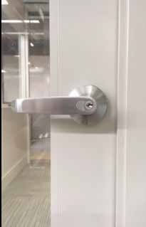
Site Ceiling                                                                         Flat Lay-In Tile Grid
Determine the installation site's ceiling type
and grid (if applicable), which will determine
attachment requirements. If you are not certain,
or encounter a different type of ceiling than
described here, send a photo to your Trendway
Technical Support team for assistance.
Information you will need:
• Identify ceiling type: Grid and Tile, Gypsum
  or other material (e.g. wood). This will deter-
  mine the type of ceiling anchors you require.
                                                          Tegular/Reveal Tile Grid
• Identify Grid ceiling tile type (if applicable):
  - Flat
  - Tegular/Reveal (see next bullet point)
  - Armstrong Silhouette
• Tegular/Reveal grids require the use of Grid
  Blocks for installation. Determine if the
  Tegular tile has a 1/4" or 3/8" tile recess
  dimension (how high it sits proud of the
  grid). There are Grid Blocks for Traditional
  and Reveal style crowns. Specify the 1/4"
  or 3/8" Block, depending on the tile recess.
                                                             Armstrong Silhouette
  Specify one Block for every 2' of panel run, or 6
  for every Crown section on order.
• Identify Grid type (if applicable): 1" Standard
  or 9/16" Thinline

                               Grid Block Installed

                                                                                       Tegular/Reveal Tile

                                                                    Flat Tile

                      Volo Planning Guide             6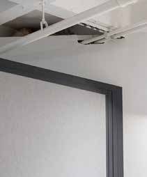
Site Ceiling

Volo Crown elements are secured to the ceiling or ceiling grid using appropriate fasteners.

         Volo Crown
                                                                                          Ceiling Grid

                                                                                           Volo Crown

         Ceiling Grid

                                                                Screw
                                                                                 Ceiling Grid

                                                                  Traditional Crown

                                          Screw
                                                           Ceiling Grid

                                          Reveal Crown

Armstrong Silhouette ceiling requires the use of Grid Clips
to attach the Crown to the grid, available for order from
Trendway (Special part number 404765).

                                           Grid Clip
                                        for Armstrong
                                      Silhouette Ceiling

                        Volo Planning Guide           7
Physical building conditions
Site conditions may affect wall placement or require special planning to accommodate. In-
spect the site and note any situations that may impact or interfere with the layout, or require
special wall connection treatment due to site wall conditions. These may include:
•   ADA requirements
•   Building walls and columns
•   Building electrical and data access
•   Convector Units (baseboard heating units)
•   Exterior Wall Start Conditions
•   Air-handling diffusers
•   Floor Type HVAC Supply and Return Grills
•   Light fixtures
•   Soffits
•   Sprinkler heads
•   Unusual Baseboard Configurations
•   Wall or floor outlets
•   Window conditions
•   Ceiling type
•   Flooring type
•   Window sill and drapery pockets

Ask the customer to look for obstructions before the product is ordered. It will be
their responsibility to remove obstructions or relocate the wall.
Once the site observation and measurements are complete:
• Identify any design modifications that should be anticipated due to site conditions.
• Review modifications with the designer before any design or layout begins
• Review modifications with the installers before installation work begins.
Once the design is finalized, it’s essential to do a thorough onsite verification of the installation
drawings to actual site dimensioning prior to installation.

Compliance with relevant regulations
Before any work is performed, be certain you are in compliance with local and/or Government
project or contract regulations. These may include, but are not limited to:
•   Building Codes
•   Building Permits
•   Test data or product sample submissions for approval
•   Certificates of Occupancy
•   Labor requirements (security clearance, trade union jurisdictions for tasks, etc.)
•   Verification of seismic bracing if required by local code
NOTE: ADA requires power outlets accessible within the range of 15" to 48" above the floor.
For Volo this requires hard-wired vertical power. Some municipalities will allow an ADA outlet
every 10-20 outlets in a work space and some municipalities may require all outlets to be ADA
accessible. Contact your local authority for clarification.

                       Volo Planning Guide        8
Installation planning checklist
___ Has the Project File tool form been completed and all Request Forms submitted?
___ Where will material be received, and who will receive?
___ Where will material be stored?
___ Are there any access or security rules governing time that installation may take place?
___ Where are walls to be installed?
___ Is the environment (i.e. heat, light, humidity, etc.) satisfactory?
___ Are there any power complications?
___ Are there any material handling obstacles (e.g. elevator/stairwell/corridor dimensions)?
___ What preparation is required for cleanliness of metal trim and panel cutting?
___ Are there any special tools or equipment required? (See Recommended Installation Tools
list on page 40.)
___ Are there complications or timing conflicts with other trades?
___ Are floor loading limitations satisfactory?
___ Ceiling type (Gypsum, drop Flat, drop Tegular/Reveal etc.)?
___ Is there anything on this job that requires extraordinary preparation?
Post-Installation
• Obtain post-installation verification of product delivery, ownership, and security.
• Complete any punch list items and “turnover” procedures (Certificate of Occupancy, etc.).
• If promotional photography is desired, obtain permission (signed release) and schedule.
NOTE: Custom Product/Specials
Trendway can support some kinds of custom product requests. See the FAQ section on page 51
for details.
Volo Planning Guide 9Volo Movable Wall
Volo Movable Walls consist of five distinct elements:
• Panel Frames
• Door Sections, Frames and Doors
• Tiles
• Connectors
• Electrical
Standard Panels
Insert Tiles
Door Height Panels
Double Sliding Doors
Glazing Tiles
Wood Framed
Wood
Flush/Solid Outsert
Tiles
Aluminum Aluminum Framed Swing Door
Framed (ADA Version Shown)
Standard
Panel
Center Mount
Glass Panel
Wood Flush/Solid
Sliding Door
Wood Framed Sliding Door
Aluminum Framed Sliding
Door Height Panels Door
7', 8' and 9' Doors Frameless Glass
Sliding Door
Volo Planning Guide 10Volo Components
Crown and Base Styles
• Since power/data routing and access is determined by Base selections, it's important to select it with this
requirement in mind.
• Vinyl Base is offered in 2", 4" and 6" heights. 2" Vinyl Base is recessed from the panel's lower rail. The 4" and 6"
Vinyl Base and the Aluminum Base sit slightly proud of it. The 6" Vinyl Base is required for horizontal electrical
access. 4" and 6"Vinyl Base can be specified in standard Smooth Trendway trim colors, but not in the Satin
Etch anodized aluminum color. The 2" Vinyl Base is available in Charcoal and Shadow Silver colors only.
• Aluminum Base affords a clean, modern aesthetic. It is 1/8" thick and sits slightly proud of the frame. Specify
the 2" Base panel frame for use with it.
• The bottom of the lower tile will align for 2" Vinyl, 4" Vinyl and Aluminum Base Frames.
• The Reveal Crown is lower in height than the Traditional Crown and slightly recessed, for a more subtle
transition to the ceiling.
• Different Base configurations can be combined within a layout, with transitions at corner or 3-way condi-
tions. Use this flexibility to enhance power/data routing and access. Note: 4" and 6" Vinyl Base requires the
use of Base End Caps at end-of-run and visible transition locations.
• NOTE: When planning for a Volo application that is not attached to a ceiling, the Freestanding Volo Kit
contains all the parts needed to effectively provide the structural integrity required for freestanding capa-
bility. Order part number VFCK. This method adds the rigidity necessary for a freestanding wall up to a 12'
run. If you desire other dimensions, contact your Trendway Architectural Specialist and design team for
help. Panels must be securely braced during installation of Volo freestanding applications. Please refer to
instruction sheet INS659 for proper installation sequence.
Crown Styles
Shown with Flat style drop ceiling Base Styles
REVEAL CROWN ALUMINUM BASE 2" VINYL BASE
Aluminum Base has a
clean, architectural look
TRADITIONAL CROWN 4" VINYL BASE 6" VINYL BASE
Required for Base modular
power/data access
Volo Planning Guide 11Panel Frames
Standard Panel Frame | Frames are constructed of 2-1/4" thick verticals (stiles) and horizontals (rails). Elements
consist of extruded anodized aluminum. Standard Frames can accommodate Center Mount Glass, and from one
(Monolithic) up to 7 Insert or Outsert Tiles per side. There is a specific Frame style to support each Base type.
NOTE: 2" Base Panels are to be specified for the Aluminium Base option, ships with Floor Runner attached.
WIDTHS: Standard Frames can be specified from a minimum of 6" to a maximum of 48" in 1/8" increments.
HEIGHTS: Standard Panel Frames can be specified from a minimum of 88" to a maximum of 120" total panel
height in 1/2" increments.
THICKNESS: 2-1/4" (plus 1/4" per side for Outsert Tiles).
48" Max., 1/8" Increments 6" Min.
STANDARD FRAME
120" Max.
½"
Increments 96" Max. Tiles:
Fabric Insert
HPL Outsert
Veneer Outsert
Glass Marker Board
88" Min.
Door Height Panel Frame | Door Height frames are similar to standard frames, and are available up to
48" wide (Center Mount Glass Tiles available up to 60") and come complete with a muntin rail installed to align
with the elevation detail of a partial-height door. They can be specified to match the available door heights of 7',
8' or 9'. Door Height frames can be further segmented below this initial segment height, but not above.
WIDTHS: Door Height Frames can be specified from a minimum of 6" to a maximum of 48" in 1/8" increments,
except for Center Mount Glazing Tiles which are available for 48" to 60" width (Door Height Frames only).
HEIGHTS: Door Height Frames can be specified from a minimum of 96" to a maximum of 120" in 1/2" increments.
5/8" Side Rail
DOOR HEIGHT FRAME
2"
No segments 1"
allowed
above
Pre-
installed
segment
9' 60" Max., 1/8"" Increments
8'
48"to 60" Wide
Center-Mount Glazing
Segments 7'
allowed Tiles Only
below
Volo Planning Guide 12Door Sections
Sliding Door Sections
Sliding Doors are ordered as Sections, which come complete with Door and Frame plus optional Soft Close
mechanism and Hardware when specified. Refer to the Cut Sheet for each Sliding Door to find detailed
specifications: Volo Frameless Glass Sliding Door, Volo Aluminum Framed Sliding Door, Volo Aluminum Framed
Double Sliding Door, Volo Wood Sliding Door, Volo Wood Double Sliding Door.
All door pulls are available in Satin Chrome 626 finish. For Double Sliding Door Post and Ladder Pulls, Black
finish is also available as a standard option. Black finish is available as a Service Part for other Door styles.
Hardware options include:
• BD and BDL – Blank Door: Allows for COM pulls or locksets. Doors must be drilled/machined on-site. BDL
includes lock (non SFIC).
• BDLICWOC – Blank Door Locking SFIC less core
• 18N – 18" Post Pull non locking
• 18L – 18" Post Pull locking (non SFIC)
• 18LICWOC – 18" Post Pull Locking SFIC less core
• 36N – 36" Post Pull non locking
• 36L – 36" Post Pull locking (non SFIC)
• 36LICWOC – 36" Post Pull Locking SFIC less core
• 72N – 72" Ladder Pull non locking
• 72L – 72" (Single Sliding Door) Ladder Pull locking (locks into floor)
• 72L – 72" (Double Sliding Door) Ladder Pull locking SFIC with core - Random Key-Best A Keyway
(locks into floor)
Note: for Frameless Glass Doors, locking is accomplished with the Patch Lock, which is separate from the Pull.
All doors except Frameless Glass can also be specified BD, BDL or BDLICWOC, the Blank Door option. The
BD option allows COM pulls or lock sets. Doors must be drilled/machined on-site as required. The BDL option
allows for COM pulls and includes a lock. Doors must be drilled/machined on-site to accommodate COM pull,
but door will be bored for our standard mortise lock which is included.
NOTE: If the Sliding Door will be positioned over Outsert Tiles when opened, a Sliding Door Outsert Kit
must be specified (SIVSDOUTKIT). The Kit includes spacers that will ensure proper clearance between the
door and the tiles.
SOFT CLOSE MECHANISM
The Soft Close ships standard with Frameless Glass Sliding Doors, and is available as an option for all door models.
Different Soft Close Mechanisms are sent for Single vs Double Sliding Door applications (below).
NOTE: Do not operate with excessive force. The Mechanism exerts slight resistance as it begins the soft open or close
operation: do not force. You can release at this point and the action completes gently and automatically.
Single Door Soft Close Mechanism Double Door Soft Close Mechanism
.47"
1.38"
A
SITSDSCM SIVSOFTCLOSE
.260"
60˚
Volo Planning Guide 13Frameless Glass Sliding Door Section | Frameless Glass Sliding Doors are 1/2" thick glass and are
available at Full Height only. 42" width is available up to 9'. Not available above 9' at this time. 48" width
is available at 8' height ONLY. Doors are specified as either Right or Left opening as viewed from the exte-
rior of the space. Volo Frameless Glass Sliding Door Cut Sheet for detailed dimensions and specifications. Find
complete door dimensions on page 17.
Frameless Glass Sliding Doors are available with three tempered glass options: Clear, Frost or Low Iron.
(Frost is installed with the matte texture on the outside of the enclosed space. All tempered glass has a visible
watermark.)
Two locking options are available, the Patch Lock and Ladder Pull. The Patch Lock (not integral to the Pull),
has a stainless steel appearance that is similar to the Satin Chrome 626 finish on the Pulls and lock cylinder.
The locking 72" Ladder Pull throws a lock rod into a 1"-deep dustproof strike. See page 22 for lock details.
NOTE: Frameless Glass Doors require a soft close mechanism.
FRAMELESS GLASS
SLIDING DOOR SECTION
Volo Planning Guide 14Aluminum Framed Single Sliding Door Section — Full Height and Partial Height |
Aluminum Framed Sliding Doors are offered in three stile/rail combinations (below). See the Volo
Aluminum Framed Sliding Door Cut Sheet for detailed dimensions and specifications. Partial Height
Doors require an upper Tile to be specified for the transom opening. Find complete door dimensions on
page 19.
2-2-2: 2" Vertical Stiles and 2" Horizontal Rails
2-2-4: 2" Vertical Stiles and 2" top Horizontal Rail paired with a 4" bottom Horizontal Rail
4-4-4: 4" Vertical Stiles and 4" Horizontal Rails (required for 72" Ladder Pull)
Aluminum Framed Single Sliding Doors are available with the same glazing options offered for panel
frames, all 1/4" tempered glass: Clear, Frost, Low Iron and Laminated. (Frost is installed with the matte texture
on the outside of the enclosed space. All tempered glass has a visible watermark.)
Doors can also be specified BD or BDL, the Blank Door
option. The BD option allows COM pulls or lock sets. Doors must be drilled/machined on-site as required. The
BDL option allows for COM pulls and includes a lock. Doors must be drilled/machined on-site to accommodate
COM pull, but door will be bored for our standard mortise lock which is included.
NOTE: The ceiling height must be greater than the height of the Partial Height Door by at least 12". If it is
less than 12" higher, then a Full Height Door Section must be specified.
The height of a Partial Height Door is specified as either 7' (84"), 8' (96") or 9' (108").
Ceiling Height
must be at least
12" greater than
a Partial Height
Door
ALUMINUM FRAMED ALUMINUM FRAMED
SLIDING DOOR SECTION — SLIDING DOOR SECTION —
FULL HEIGHT PARTIAL HEIGHT
Volo Planning Guide 15Aluminum Framed Double Sliding Door Section — Full Height Only | Aluminum Framed
Double Sliding Doors are offered in three stile/rail combinations (below). See the Volo Aluminum
Framed Double Sliding Door Cut Sheet for detailed dimensions and specifications. Find complete door
dimensions on page 19.
2-2-2: 2" Vertical Stiles and 2" Horizontal Rails
2-2-4: 2" Vertical Stiles and 2" top Horizontal Rail paired with a 4" bottom Horizontal Rail
4-4-4: 4" Vertical Stiles and 4" Horizontal Rails (required for 72" Ladder Pull)
Aluminum Framed Double Sliding Doors are available with the same glazing options offered for panel
frames, all 1/4" tempered glass: Clear, Frost, Low Iron and Laminated. (Frost is installed with the matte texture
on the outside of the enclosed space. All tempered glass has a visible watermark.)
Doors can also be specified BD ALUMINUM FRAMED
or BDL, the Blank Door option. DOUBLE SLIDING DOOR
The BD option allows COM pulls or SECTION
lock sets. Doors must be drilled/
machined on-site as required. The
BDL option allows for COM pulls
and includes a lock. Doors must be
drilled/machined on-site to accom-
modate COM pull, but door will
be bored for our standard mortise
lock which is included.
Track 150"
Min. 36" Min. 36"
Panel Panel For proper clearance, panels at
least 36” wide must be specified
to the right and left of the double
door.
Volo Planning Guide 16Wood Single Sliding Door Section — Full Height and Partial Height | Doors offered in two
styles, Flush/Solid or Full Lite. They can be specified in HPL or Veneer surface. See the Volo Wood Sliding
Door Cut Sheet for detailed dimensions and specifications. Find complete door dimensions on page 19.
Full Lite Wood Doors are available with the same glazing options offered for panel frames, all tempered
glass: Clear, Frost, Low Iron or Laminated. (Frost is installed with the matte texture on the outside of the en-
closed space. All tempered glass has a visible watermark.)
Doors can also be specified BD or BDL, the Blank Door
option. The BD option allows COM pulls or lock sets. Doors must be drilled/machined on-site as required. The
BDL option allows for COM pulls and includes a lock. Doors must be drilled/machined onsite to accommodate
COM pull, but door will be bored for our standard mortise lock which is included.
NOTE: The ceiling height must be greater than the height of the Partial Height Door by at least 12". If it is less than
12" higher, then a Full Height Door Section must be specified.
The height of a Partial Height Door is specified as either 7' (84"), 8' (96") or 9' (108").
Ceiling Height
must be at least
12" greater than
a Partial Height
Door
WOOD SLIDING DOOR
SECTION — FULL HEIGHT WOOD SLIDING DOOR
(FULL LITE) SECTION — PARTIAL
HEIGHT (FULL LITE)
Volo Planning Guide 17Wood Double Sliding Door Section — Full Height Only | Doors offered in two styles, Flush/
Solid or Full Lite. They can be specified in HPL or Veneer surface. See the Volo Wood Double Sliding Door
Cut Sheet for detailed dimensions and specifications. Find complete door dimensions on page 19.
Full Lite Wood Doors are available with the same glazing options offered for panel frames, all tempered
glass: Clear, Frost, Low Iron or Laminated. (Frost is installed with the matte texture on the outside of the en-
closed space. All tempered glass has a visible watermark.)
Doors can also be specified BD or BDL, the Blank Door option. The BD option allows COM pulls or lock sets.
Doors must be drilled/machined on-site as required. The BDL option allows for COM pulls and includes a lock.
Doors must be drilled/machined onsite to accommodate COM pull, but door will be bored for our standard
mortise lock which is included.
WOOD FRAMED DOUBLE
SLIDING DOOR SECTION
Track 150"
Min. 36" Min. 36"
Panel Panel For proper clearance, panels at
least 36” wide must be specified
to the right and left of the double
door.
Volo Planning Guide 18Door Dimensions
Single Door Door Type Door Width Clear Opening
Style (Nominal) (Nominal/Installed)
Single Sliding Frameless Glass Single Sliding Door 42" and 48" 34" and 40"
Door
Aluminum Framed Single Sliding 42" and 48" 34" and 40"
Door (2-2-2, 2-2-4, 4-4-4)
Wood Single Sliding Door, Flush/ 42" and 48" 34" and 40"
Solid
Wood Single Sliding Door, Full Lite 42" and 48" 34" and 40"
(Frame is 4" top, 8" sides, 10" bot-
tom)
Single Swing Aluminum Framed Swing Door 36" 33"
Door (4-4-4 and ADA-compliant 4-4-10)
Wood Swing Door, Flush/Solid 36" 33"
Wood Swing Door, Full Lite 36" 33"
(Frame is 4" top, 6" sides, 9" bottom)
Double Door Door Type Door Clear Opening for Clear Clear
Style Width 2-2-2 and 2-2-4 Opening Opening
(installed) for 4-4-4 (installed)
(installed)
Double Sliding Aluminum Framed Double 39" 67" 65-1/2"
Door Sliding Door (2-2-2, 2-2-4,
4-4-4)
Double Sliding Wood Full Lite Double Sliding 39" 65-1/2"
Door Door
Double Sliding Wood Flush Double Sliding 39" 65-1/2"
Door Door
Volo Planning Guide 19Swing Door Frames
Swing Door Frames
Volo Swing Door Frames are constructed of 2-1/4" thick extruded aluminum vertical and horizontal elements.
Swing Door Frames are available in all three base styles.
NOTE: Doors must be specified separately, they are not included with the frame.
WIDTH: Swing Door Frames are available 39" wide only.
HEIGHTS: Swing Door Frames can be specified from a minimum 88" (96" for Partial Height) to a maximum
120" in 1/2" increments.
NOTE: Swing Doors cannot install adjacent to a Reveal Wall Start without a minimum 6" panel between them.
Swing Door Frame — Full Height | Full Height Swing Door Frames require a Full Height Door of
identical height and width. The height of the door frame is determined by the ceiling height, and the Door
Height is then specified separately to match. There is no transom opening with a Full Height frame. They can
be ordered in heights ranging from 88" to 120" in 1/2"
increments. The Frame offers up to 1/2" of total height
adjustment.
Door Size Actual Door Clear
Width Opening
36" x 7' 36" 33"
36" x 8' 36" 33"
36" x 9' 36" 33"
36" x 10' 36" 33"
SWING DOOR FRAME –
FULL HEIGHT
39"
120" Max.
½" Increments
88" Min.
Volo Planning Guide 20Swing Door Section — Partial Height | There is a transom opening with a Partial Height Sliding
Door Frame, with a minimum tile height of 8" — a Volo upper tile must be specified for this opening. The
Frame offers up to 1/2" of total height adjustment.
Note: If the ceiling height is not higher than a Partial Height Door by at least 12", a Full Height Door Section
and Full Height Door must be specified instead.
Door Size Actual Door Clear
Width Opening
36" x 7' 36" 33"
36" x 8' 36" 33"
36" x 9' 36" 33"
SWING DOOR FRAME –
PARTIAL HEIGHT
Ceiling Height must be at
least 12" greater than
a Partial Height Door
39"
8" Minimum
Tile Height —
a Tile must be 120" Max.
specified
½" Increments
96" Min.
Volo Planning Guide 21Volo Doors
Doors | Volo Doors are available in Sliding (Frameless Glass, Aluminum Framed, Wood Flush/Solid
and Full Lite) and Swing (Aluminum Framed, Wood Flush/Solid and Full Lite) models. All doors must be
specified either Right or Left Hand. See the illustration below to determine which to specify. NOTE: All
Doors are ADA compliant, with a minimum 32" clear opening (see detailed Dimension, page 16-17). They
are available with the same glazing options offered for panel frames, all tempered glass: Clear, Frost, Low Iron
or Laminated. (Frost is installed with the matte texture on the inside of the enclosed space. All tempered
glass has a visible watermark.)
Doors must be specified Full Height or Partial Height to match the specified Frame or Section.
SWING DOOR SLIDING DOOR Right-Hand Slide
Side 2
Outside Side 1
Left-Hand Slide
Right-Hand Swing* Left-Hand Swing* Side 2
*Based on Doors swinging out of the room Outside Side 1
and into the hallway.
SINGLE DOOR HARDWARE OPTIONS
NOTE: Swing doors do NOT have • BD and BDL - Blank Door: Allows for COM pulls or locksets. Doors must
a BD (Blank Door) hardware option. be machined onsite. BDL includes non-SFIC lock. (Sliding Door only)
(See options right) • NH - No Hardware: Allows for COM lever sets. Standard door prep iden-
tified on Volo Aluminum Framed Swing Door cut sheet.
• LP - Lever Passage set non-locking
• LL - Lever Lock set random key locking (non SFIC)
• LLICWOC – Lever Lock set, SFIC (COM core, not included)
Single Frameless Glass Sliding Door | Frameless Glass Sliding Doors are 1/2" thick and available at
Full Height only. The 42" width is available up to 9', and the 48" width is available at 8' height ONLY. The Soft
Close option is required for this door.
Single Aluminum Framed Glass Doors | Aluminum Framed Glass Doors are constructed of extruded
aluminum. They are 1-3/4" thick and accept 1/4" glazing. Doors can be specified from 88" to 120" high in 1/2"
increments. Doors are offered in either Trendway trim paint colors or in an Anodized Aluminum finish.
Aluminum Sliding Door Sections may be specified 2" on all sides (2-2-2), with 2" vertical stiles, 2" top horizontal
rail and 4" bottom horizontal rail (2-2-4), or 4" wide on all sides (4-4-4).
Aluminum Swing Door Frames are offered 4" on all sides (4-4-4) or ADA-compliant 4" top and vertical rails with
10" bottom horizontal rail (4-4-10).
Wood Doors | Wood doors are 1-3/4" thick and accept 1/4" glazing. Wood doors can be specified in
either a Flush/Solid or Full Lite style.
Full Lite Wood Sliding Doors have 8" vertical stiles, 4" top horizontal rail and 10" bottom horizontal rail. Full Lite Wood
Swing Doors have 6" vertical stiles, 4" top horizontal rail and 9" bottom horizontal rail. They are offered in either High
Pressure Laminate (HPL) or Wood Veneer. Doors can be specified from 88" to 120" high in 1/2" increments.
Note: For conference rooms over 150 s.f. in size or any classroom that holds 10 people or more,
swing doors are typically required to meet national access and egress codes.
Volo Planning Guide 22SINGLE SLIDING DOORS
Note: the Frost glass option is installed with
FRAMELESS GLASS
the matte texture on the inside of the enclosed
SINGLE SLIDING DOORS
space. All tempered glass has a visible water-
mark.
ALUMINUM FRAMED
SINGLE SLIDING DOORS
2-2-2 2-2-4 4-4-4
WOOD SINGLE
SLIDING DOORS
Flush/Solid Full Lite
Volo Planning Guide 23DOUBLE SLIDING DOORS
ALUMINUM FRAMED DOUBLE SLIDING DOOR
Aluminum Framed Double
Sliding Doors are available
in 2-2-2, 2-2-4 and 4-4-4
styles. Refer to the previous
page to view these style
options.
WOOD DOUBLE SLIDING DOORS
Flush/Solid Full Lite
Volo Planning Guide 24SINGLE SWING DOORS
ALUMINUM FRAMED SWING DOORS WOOD SWING DOORS
4-4-4 4-4-10 (ADA) Flush/Solid Full Lite
Volo Planning Guide 25Door Hardware | Several architectural-style door hardware options are available. All Door Pull styles are
available as Locking and Non-Locking. Locking is available Standard or Small Format Interchangeable Core (SFIC).
NOTE: Refer to Hardware Cut Sheets for specification details.
SFIC locks are widely used where re-keying is frequent. New cores (COM) can easily be changed out as
required. See the FAQ section for details, page 55.
For information about COM hardware accommodation see the FAQ section, page 55,
SINGLE/DOUBLE SLIDING DOOR PULL OPTIONS SINGLE SWING DOOR PULL
18" Post Pull 36" Post Pull ADA Lever Set SFIC Option
12" centerline-to-centerline of 22.5" centerline-to- Lever Lockset shown, SFIC lock. (COM Core not included)
mounting hardware. centerline of mounting Passage Set available.
hardware.
72" Ladder Pull MORTISE LOCK PATCH LOCK
Available for Wood and 4-4-4
Aluminum Framed Doors only.
Option for Frameless
The 72" Single Sliding Door Locking Ladder Pull locks into floor Glass Sliding Door only
with a Schlage "C" keyway. The 72" Double Sliding Door Locking
Standard Lock shown —
Ladder Pull ships with SFIC with core - Random Key-Best A
Keyway. Both lock into the floor and throw a lock rod into a SFIC Option available,
1"-deep dustproof strike (supplied). This option requires floor COM Core, not included
machining at the job site by a certified installer (above right).
NOTE: Master Key Statement
Each end user needs their own unique Master Key system. It is most effective for a local locksmith to work with
the client on their specific setup, so if changes or additions are required there is a nearby professional who
understands their system and can address their future needs. For that reason, supplying master keyed products
directly from Trendway is not in the best interest of the end user.
Trendway can provide blank cylinders, without keying, to assist in this process. If frequent changes are anticipated,
an interchangeable core system should be used so the cylinder can be removed without disassembling the lock.
Volo Planning Guide 26Volo Tiles
Volo offers three basic Tile styles:
Insert Tiles | Insert Tiles sit flush to the frame and leave the entire aluminum frame elements exposed. Tiles
are offered for Panel widths from 6" to 48" in 1/8" increments and heights from 8" to 114" in 1/2" increments
(Fabric Tiles to 96" only).
Outsert Tiles | Outsert Tiles sit 1/4" proud of the frame and leave a 1/4" reveal of frame exposed
between tiles. They consist of Upper and Lower Tiles. Tiles are offered for Panel widths from 6" to 48" in 1/8"
increments and heights from 8" to 96" in 1/2" increments,
Lower Outsert Tiles are required for the lowest tile position, where a tile installs on the base frame. They must
be specified for this position to allow the full range of height adjustment for the panel. Every panel will have at
least one Lower Tile, and monolithic Tiles are always Lower Tiles.
Upper Outsert Tiles are required for tile positions other than the lowest position where a tile installs on the
base frame.
Back-Painted Outsert Tiles ship separately and are installed onsite. See note on page 24.
NOTE: If the Outsert Tiles will be positioned behind a Sliding Door when it is open, a Sliding Door Outsert Kit
must be specified (SIVSDOUTKIT). The Kit includes spacers to ensure proper clearance between the door and tiles.
Center Mount Glazing Tiles | Center Mount Glazing Tiles provide transparency or translucency
anywhere on a Volo panel. Glazing Tiles are Class A fire rated when specified with tempered glass. Center
Mount Glazing Tiles are available in widths up to 48" (60" for Door Height Panels only), and in heights up to 114".
Note: Frost glass option is installed with the matte texture on the outside of the enclosed space. All tempered
glass has a visible watermark. Note: 3form is only available in a maximum width of 48" and height of 74-1/4".
Insert Tiles expose the entire aluminum frame Outsert Tiles reveal 1/4" of frame and sit 1/4" proud of it
Center Mount Glazing Tiles
Volo Planning Guide 27Volo Tiles
Volo Tiles are available in a wide range of functional and surface material options.
• Vinyl (Insert only)
• HPL (High Pressure Laminate - see Note below)
• Veneer
• Tackable/Fabric (Insert only, maximum 96" height)
• 1/4" Center Mount Glazing — standard options Clear Tempered, Clear Laminated, Frost, Low Iron and 3form.
(Frost is installed with the matte texture on the outside of the enclosed space. All tempered glass has a
visible watermark.)
• Back Painted Glass Marker Board (Outsert style only - Tiles ship separately crated and are installed to the
Panel onsite.)
• Back Painted Glass Marker Board - Steel Backed (enables use of strong magnets for attachment of items —
Outsert style only)
Tackable Fabric, HPL Laminate Veneer Vinyl
NOTE:
• Outsert Tiles have a maximum height of 96". Lower Outsert Tiles must
be specified for the lowest tile position on a frame, where the tile installs
on the base frame. This allows the full range of panel height adjustment.
Upper Outsert Tiles are specified for all tile positions above the Lower
Outsert Tile.
For Outsert Tiles, if the chosen HPL does not have a matching Trendway
edge band, the edge defaults to Charcoal. The Charcoal edge is largely
invisible in the shadow of the reveal, but the 1/4" edge will be visible at Center Mount Glazing, Back
the end of the run. Painted Glass Outserts
NOTE: Laminates with standard matching edge will be constructed with
the matching material. Tiles specified in all other laminate colors are
constructed with Charcoal edge. Edge is minimally visible in the reveal.
• Tackable Fabric Insert Tiles have a maximum height of 96".
• Vinyl, Laminate, Veneer and Center Mounted Glazing Insert Tiles are available in heights up to 114".
• Laminate Tiles can be specified in any HPL color in the Trendway offering. For Outsert Tiles see note about
matching edge above.
• The grain of Wood Grain HPL and Veneer runs vertically. Grain is not matched from tile to tile.
• Back Painted Glass Tiles are available in a selection of 3 standard colors. They can also be custom matched to
the customer's choice of Pantone colors. A $250 matching fee is required and extended lead times apply see
the Volo Price List for details. NOTE: Tiles ship separately crated and are installed to the Panel onsite.
Volo Planning Guide 28Volo Tiles
Component Mounting
• Volo Vinyl, HPL & Veneer surfaced Insert and Outsert Tiles will accommodate direct component
mounting.
• Components attach with a standard screw and bracket supplied by the installer. The brackets should
have a screw at least every 8", a minimum of 4 per bracket.
• Passes ANSI/BIFMA X5.6, can accommodate loads up to 150 lb., or 50 lb. per linear foot including the
unit itself. NOTE: There are no run length restrictions for panels attached to the ceiling. Some restrictions
apply to Freestanding applications. Contact your Trendway Architectural Product Specialist for details.
• If the unit is later removed, simply replace the tiles.
• Not applicable to Glass or Tackable Tiles.
Volo Planning Guide 29Horizontal Connectors
Horizontal Connectors are the system framing elements that connect the panels to the ceiling and floors.
Ceiling Crown | Ceiling Crown is available in two styles - Traditional and Reveal. Comes in 12' lengths. (See
notes about Ceiling Grid Blocks on page 6.) Freestanding applications require the Freestanding Volo Kit; see
specification details on page 11.
Base Trim | Vinyl Base is available in 12' lengths, Aluminum Base in 9' lengths so order accordingly (one
length per panel). Specify Base to match the frame style. The 6" Traditional Base allows for baseway power and
data access. 90° Corner Base is included for a clean, finished appearance for 90° and End-of-Run conditions.
End Caps provide a finished appearance on the 4" and 6" Vinyl Base in an end-of-run condition. They are
included when End of Run Connectors and Door Frames are ordered for 4" and 6" Vinyl Base. The 6" End Cap
is handed and should be ordered for every outside corner condition.
Floor Runner | Floor Runner needs to be ordered when specifying 4" and 6" Vinyl Base Frames. For the 2"
and Aluminum Base Frame, Floor Runner ships attached to the frame and does not need to be ordered separately.
CROWN (Reveal style shown)
FLOOR RUNNER for
ALUMINUM BASE
(Included — ships attached)
FLOOR RUNNER for
4" and 6" VINYL BASE
(Specified and shipped
separately)
BASE
VINYL BASE END CAP FOR END-OF-RUN CONDITIONS VINYL BASE CORNER BASE COVER FOR 90° CONDITIONS
(4" and 6" Vinyl Base only) (4" and 6" Vinyl Base only)
Inserts in the end Installed
of the Base Cover 12" 12"
(6" Base shown)
Volo Planning Guide 30Horizontal Connectors
Panel Extenders PANEL EXTENDER
PANEL EXTENDER part # 395796
(Can mount to bottom or top of panel)
(Profile View)
A Panel Extender allows the
height of a panel to extend by 1"
at the Base or Crown. Supplied in
12' lengths. This is a field applied
part. Cut the Panel Extender to
the exact width measurement
of the panel it will be applied to.
Apply to the Frame as shown
right, using a minimum of 4
3/8" Dia. Through
screws. Apply top or bottom for One Wall for Driver
4" and 6" Vinyl Base, top only for Bit (4 places)
the 2" Vinyl and Aluminum Base. 1/8" Dia. Pilot Hole
One Wall for Fas-
tener (4 places)
Volo Panel with Traditional Crown
CEILING
CEILING
CEILING
.500" 1.500" 2.500"
PANEL AS SPECIFIED PANEL AS SPECIFIED WITH PANEL AS SPECIFIED WITH
ONE PANEL EXTENDER TWO PANEL EXTENDERS
Volo Panel with Reveal Crown
CEILING
CEILING
CEILING
.500" 1.988" 2.978"
PANEL AS SPECIFIED PANEL AS SPECIFIED WITH PANEL AS SPECIFIED WITH
ONE PANEL EXTENDER TWO PANEL EXTENDERS
Volo Planning Guide 31Vertical Connectors
Volo Vertical Connectors are the elements that finish Volo panel runs, join them to existing building walls or
join two or more Panels. Typical conditions are Wall Starts, In-Line, 3-Way, 4-Way, Corner and End of Run. All
Connectors except Reveal Wall Starts are made from the highest grade extruded aluminum and can be specified
in all Trendway trim paint colors or in an Anodized Aluminum finish.
Wall Starts | Wall Starts create a clean finished connection with an existing building wall.
• Adjustable Wall Starts offer +/- 1/2" of adjustability. They match frame elements and provide flexibility to
cleanly attach to wall conditions. If conditions require, additional adjustment range can be achieved by
removal of Wall Start Part B (see image below) and/or addition of Filler Connectors (page 31).
Note: Select the "W" Wood Block option when specifying an Adjustable Wall Start that will attach to a
Swing Door section. This is the only condition where it is required. The Blocks are inserted between the two
rail parts to provided added stability.
Continued, next page
ADJUSTABLE WALL START ADJUSTMENT RANGE
2-1/2"
AS DESIGNED AND PLANNED
2-1/8"
FULLY COMPRESSED —
STANDARD
3"
ADJUSTABLE WALL START
FULLY EXTENDED — STANDARD
1-1/4"
COMPRESSED WITHOUT
ADJUSTABLE WALL START (Plan View) "B" PART (Right)
4"
Part A Part B
EXTENDED WITH ADDITIONAL
1" FILLER CONNECTOR
(Page 30)
Volo Planning Guide 32Wall Starts, Continued
• Reveal Wall Starts create a subtle, recessed wall connection where minimal (+/- 1/4") adjustability is
required. Use in conjunction with an Adjustable Wall start in the run for more flexibility. They are a good
choice for transition when connecting with other Architectural Wall products. Available in Charcoal and
Shadow Silver colors only. Not for use directly adjacent to doors or in freestanding applications.
• Angled Wall Start Wood Blocks (VCASB10) can be specified in a range of degrees of angle to
accommodate attachment to a wide variety of fixed site wall conditions. They are considered an extension of
the architecture, not part of the wall system. Specify any angle between 3 degrees and 87 degrees. Detailed
drawing must be submitted with the order. Available in standard Smooth paint finish colors. Wood Blocks
(WB10) can also be specified to be cut onsite when precise wall angle measurements are not available when
the order is placed.
• For irregular site wall conditions, use a solid monolithic Vinyl or Laminate insert panel. Order the panel wide
enough to reach the site wall or window glass. Order Traditional Crown for wall connection. Cut on-site as
required.
REVEAL WALL START
REVEAL WALL START (Plan View)
ANGLED WALL START WOOD BLOCKS MONOLITHIC INSERT PANELS WITH VINYL OR
CAN BE SPECIFIED TO ACCOMMODATE HPL SURFACES CAN BE CUT ON-SITE TO ACCOM-
SITE WALL ANGLES OF BETWEEN MODATE IRREGULAR WALL CONDITIONS, USING
3 AND 87 DEGREES TRADITIONAL CROWN FOR TRIM AROUND THE
(Curved Wall Pictured Above) CUT EDGES
Cannot be used in freestanding
applications
Wood Block (Plan View)
1-3/4"
END OF RUN
(Plan View)
End of Run Connectors | End of Runs are used to create a finished panel when it
does not join another panel or an existing building element.
Volo Planning Guide 33Inline Connectors
Inline Electrical Connectors include covers for optional electrical punch-outs or open duplex boxes to
accommodate hard wire power and data. Switches and Power elements must be provided and installed
onsite by an electrician. They can be utilized as powered or non-powered. Modular power may not be
utilized in vertical Inline Connectors; power must be hard-wired onsite by a qualified electrician.
Inline Angle Condition Wood Block Connectors are used to attach panels together at a range of angles
other than 90 degrees, specified from 3 degrees to 87 degrees. They maintain 1.75" center-of-clip to
center-of-wood-block dimension for layout planning purposes. They ship with two Stiles cut to size
and attached to the Wood Block, and with 10 panel-to-panel connectors. Specify ceiling height in 1/2"
increments.
Section to be
removed for
hard wire
applications
INLINE ANGLE CONDI-
2-WAY INLINE CONNECTOR 3-WAY INLINE CONNECTOR TION WOOD BLOCK
(Plan View) (Plan View) CONNECTOR
NOTE: 2-Way Inline Connectors can only accommodate a high-voltage box to be
installed on one side of the post. The other side can still accommodate low-voltage (phone/data) cables.
The punch-out dimension is 2.7" x 1.38". Punch-out heights available are:
6" – Data Height
18" – Standard Height Power (ADA compliant)
32" – Work Height Power
45" – Switch Height
72" – AV Height
NOTE: Punch-out locations cannot be back-to-back
on both sides of the connector.
Punch-out Description:
C0B 45" Switch Height with Box
C2AB 18" Standard Height with Box
C3B 32" Work Height with Box
C4B 6" Data Height with Box
C5AB 18" Standard and 32" Work Height with Boxes
C6AB 18" Standard and 6" Data Height with Boxes
C7B 32" Work Height and 6" Data with Boxes
C8B Special Punch Out location with Box
AVB 72" AV Height
AVC5AB 72" AV, 18" Standard and 32" Work Height with Boxes
AVC6AB 72" AV, 18" Standard and 6" Data Height with Boxes INLINE CONNECTORS OFFER VERTICAL ACCESS
TO POWER/DATA. POWER MUST BE HARD-
WIRED ONSITE BY A QUALIFIED ELECTRICIAN.
Vertical Power Routing | For power to be routed vertically, hard wiring in the field
required. The Hard wire Box (VVEB) is a custom size and comes with 2 mounting brackets. UL
listed. Engineered to fit Volo. Dimensions are 2" x 1-1/3" x 6-1/2".
ELECTRICAL HARD WIRE BOX
VVEB
Volo Planning Guide 34Condition Connectors
90° Corner Connectors | Corner Connectors vertically connect panels in 90° corner conditions. A 90°
Corner Connector includes a Vertical Cover.
Note; A Corner Base is included when a 4" or 6" Vinyl Base height options is specified. Other base options do
not utilize a corner.
90° CORNER CONNECTOR
(Plan View)
2, 3 and 4 Way Connectors | Vertically connect panels in 3-way, 4-way and 135° 2-way conditions.
3-WAY PANEL CONNECTOR 90°/135° 4-WAY PANEL CONNECTOR 2-WAY 135° PANEL CONNECTOR
(Plan View) (Plan View) (Plan View)
Filler Connectors | 1" and 1/2" Filler Connectors
provide the flexibility to add incremental width
to a panel run to respond to field requirements.
They are inserted in conjunction with other Vertical
Connectors. They are best placed at the end of a run
next to a Wall Start Connector. Filler Connectors can 1/2" FILLER CONNECTOR
(Plan View)
be inserted "stacked" on top of each other in any
combination, for more added incremental width.
1" FILLER CONNECTOR
(Plan View)
Volo Planning Guide 35Transition Connectors — Volo to Clear Wall
Volo to Clear Wall Frame Connectors provide an easy connection and clean lines when transitioning between
Volo and Clear Wall Glass Insert runs. Remember that Volo is 2-1/4" and Clear Wall is 3-1/4" thick, so that
when bringing the two systems together, the centerlines will not align perfectly and there will be a step
on both sides of the connectors (see Fig 1 below).
CLEAR WALL TO VOLO TRANSITION POSTS
3-Way Connector - CVC
FIG. 1
Volo
Clear
7/8" Centerline
Post
Clear Clear
3/8"
TOP VIEW
3.75" Volo
Volo Clear Centerline
3"
3-Way Connector - VCC Inline Connector
Clear Volo
Clear
Volo
Clear
TOP VIEW
TOP VIEW
3.375" 3.375"
3.75" 2.5"
3-Way Connector - VVC 90 Degree Connector
Volo
Clear
Volo
Clear Volo
TOP VIEW
TOP VIEW
3.375" 2.75"
2.75"
3.375"
Volo Planning Guide 36Power and Data
It's important to establish an understanding of the customer's estimated power and data
requirements early in the design process. For an installation where there is a substantial need
for power and data access, the 6" Vinyl Base is required. Aluminum, 2" Vinyl and 4" Vinyl Base
models can accommodate power only within 2- and 3-way Vertical Connectors, which will
require individual hard wired infeed from building power.
Modular Power | 8 Wire System
The Volo modular electrical system provides many pathways for accessing building electrical power and
supplying it where and when it’s needed. Power feeds, Power Blocks, power jumpers and duplexes all work
together to supply power in the 6" Traditional Base. Power in the Vertical Inline Connectors can be hard wired
onsite by a qualified electrician — Punch outs and Boxes are supplied by Trendway (see Vertical Power Routing,
next page). This lay in capability makes electrical installation and relocations a snap.
Volo’s 8 wire 4-2-2 modular power system is identical in most respects to that of the rest of the Trendway family
power components.
Three General Circuits, One Dedicated
8-WIRE 4-2-2 POWERPAC
Circuit Name Circuit-1 Circuit-2 Circuit-3 Circuit-4
Dedicated WIRING DIAGRAM
Catalog Number PD1 PD2 PD3 PD4
Circuit Symbol I II III IVΔ
GRAY NEUTRAL-2
WHITE NEUTRAL-1
GRN/YEL ISO GRND
GREEN GROUND
PINK HOT-4
BLUE HOT-3
RED HOT-2
BLACK HOT-1
Ceiling Feed
Accessing Building Power | Ceiling and Base
CEILING FEED
The Ceiling Feed connects a building's electrical supply from a ceiling
access to the base electrical system. It distributes up to four 20 amp
circuits and attaches directly to a Power Block at any one of the
four distribution connections. UL Listed and CSA certified.
Base Feed
END MOUNT BASE FEED (6" Vinyl Base Only)
The End Mount Base Feed is designed to bring building electrical to the Volo electrical system. The modular
end of the Base Feed occupies one duplex location on a Power Block. Use of the End Mount Base Feed
reduces duplex capacity by one. For use with the 6" Vinyl Base only.
Vertical Data Routing | Data cables (Cat. 5) can be routed vertically in the Vertical Connectors.
2-WAY INLINE CONNECTOR 3-WAY INLINE CONNECTOR 90° CORNER CONNECTOR ADJUSTABLE WALL START
Outside Maximum: 8 Core Maximum: 20 36 Maximum Minimum 40, Maximum 56
Core Maximum: 20 Outside Maximum: 8
Outside Maximum: 8
Volo Planning Guide 37You can also read