Maintenance and Service Guide - OMEN by HP 17 Laptop PC - Geizhals Static Content
←
→
Page content transcription
If your browser does not render page correctly, please read the page content below
Maintenance and Service Guide

OMEN by HP 17 Laptop PC
© Copyright 2019 HP Development Company,           Product notice                                      Software terms
L.P.
                                                   This guide describes features that are common       By installing, copying, downloading, or
Bluetooth is a trademark owned by its              to most models. Some features may not be            otherwise using any software product
proprietor and used by HP Inc. under license.      available on your computer.                         preinstalled on this computer, you agree to be
DisplayPort and the DisplayPort logo are                                                               bound by the terms of the HP End User License
trademarks owned by the Video Electronics          Not all features are available in all editions or   Agreement (EULA). If you do not accept these
Standards Association (VESA) in the United         versions of Windows. Systems may require            license terms, your sole remedy is to return the
States and other countries. Intel, Core, and       upgraded and/or separately purchased                entire unused product (hardware and software)
Optane are trademarks of Intel Corporation or      hardware, drivers, software or BIOS update to       within 14 days for a full refund subject to the
its subsidiaries in the U.S. and/or other          take full advantage of Windows functionality.       refund policy of your seller.
countries. NVIDIA, GeForce, and Optimus are        Windows 10 is automatically updated, which is
trademarks and/or registered trademarks of         always enabled. ISP fees may apply and              For any further information or to request a full
NVIDIA Corporation in the U.S. and other           additional requirements may apply over time         refund of the price of the computer, please
countries. SDHC, SDXC, and microSD are             for updates. Go to http://www.microsoft.com         contact your seller.
trademarks or registered trademarks of SD-3C       for details.
LLC. Windows is either a registered trademark
                                                   To access the latest user guides, go to
or trademark of Microsoft Corporation in the
                                                   http://www.hp.com/support, and follow the
United States and/or other countries. Miracast
                                                   instructions to find your product. Then select
is a registered trademark of the Wi-Fi Alliance.
                                                   User Guides.
The information contained herein is subject to
change without notice. The only warranties for
HP products and services are set forth in the
express warranty statements accompanying
such products and services. Nothing herein
should be construed as constituting an
additional warranty. HP shall not be liable for
technical or editorial errors or omissions
contained herein.

First Edition: May 2019

Document Part Number: L64245-001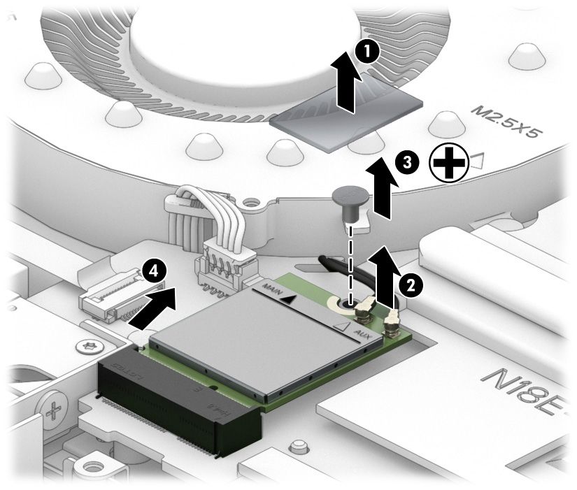
Important Notice about Customer Self-Repair Parts
       IMPORTANT: Your computer includes Customer Self-Repair parts and parts that should be accessed by only
       an authorized service provider. See Chapter 5, "Removal and replacement procedures for Customer Self-
       Repair parts," for details. Accessing parts described in Chapter 6, "Removal and replacement procedures for
       authorized service provider parts," can damage the computer or void your warranty.

                                                                                                                     iii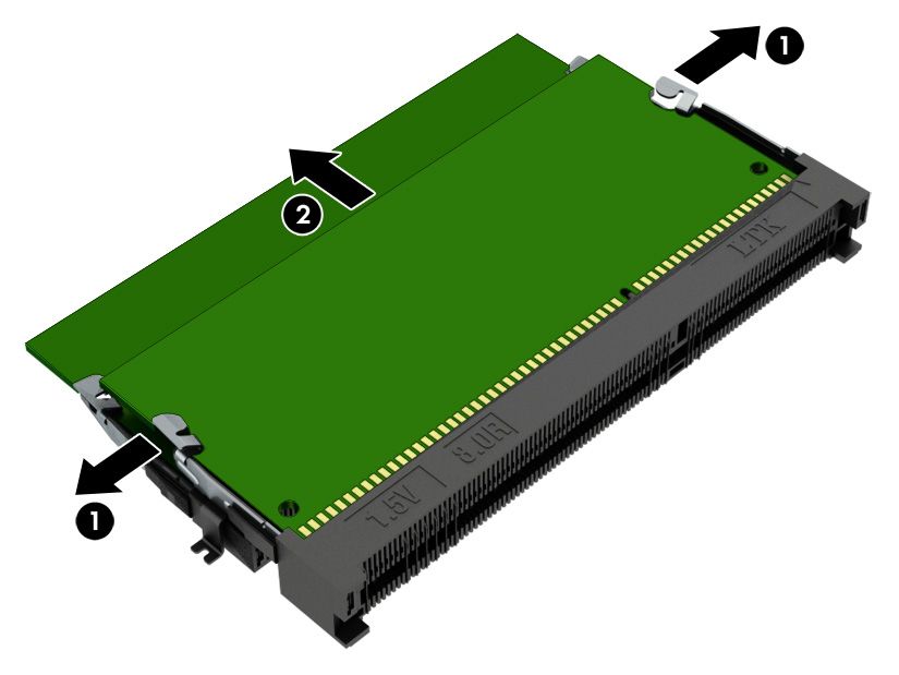
iv Important Notice about Customer Self-Repair Parts
Safety warning notice
       CAUTION: To reduce the possibility of heat-related injuries or of overheating the device, do not place the
       device directly on your lap or obstruct the device air vents. Use the device only on a hard, flat surface. Do not
       allow another hard surface, such as an adjoining optional printer, or a soft surface, such as pillows or rugs or
       clothing, to block airflow. Also, do not allow the AC adapter to contact the skin or a soft surface, such as
       pillows or rugs or clothing, during operation. The device and the AC adapter comply with the user-accessible
       surface temperature limits defined by applicable safety standards.

                                                                                                                           v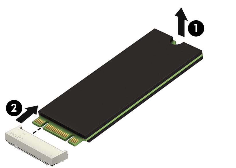
vi Safety warning notice
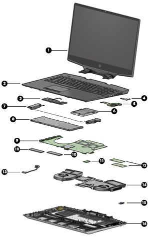
Table of contents

1 Product description ....................................................................................................................................... 1

2 Getting to know your computer ...................................................................................................................... 5
              Right side ............................................................................................................................................................... 5
              Left side ................................................................................................................................................................. 6
              Rear ........................................................................................................................................................................ 7
              Display .................................................................................................................................................................... 8
              Keyboard area ........................................................................................................................................................ 9
                               Touchpad ............................................................................................................................................. 9
                               Lights ................................................................................................................................................. 10
                               Button ................................................................................................................................................ 11
                               Special keys ....................................................................................................................................... 12
              Bottom ................................................................................................................................................................. 13
              Labels ................................................................................................................................................................... 14
              HP OMEN Command Center ................................................................................................................................. 15

3 Illustrated parts catalog .............................................................................................................................. 16
              Computer major components .............................................................................................................................. 16
              Mass storage devices ........................................................................................................................................... 19
              Display assembly subcomponents ...................................................................................................................... 20
              Cables ................................................................................................................................................................... 21
              Miscellaneous parts ............................................................................................................................................. 22

4 Removal and replacement procedures preliminary requirements .................................................................... 24
              Tools required ...................................................................................................................................................... 24
              Service considerations ......................................................................................................................................... 24
                               Plastic parts ....................................................................................................................................... 24
                               Cables and connectors ...................................................................................................................... 24
                               Drive handling ................................................................................................................................... 25
                               Workstation guidelines ..................................................................................................................... 25
              Electrostatic discharge information .................................................................................................................... 25
                               Generating static electricity .............................................................................................................. 26
                               Preventing electrostatic damage to equipment ............................................................................... 26
                               Personal grounding methods and equipment .................................................................................. 27
                               Grounding the work area ................................................................................................................... 27
                               Recommended materials and equipment ........................................................................................ 27

                                                                                                                                                                                                vii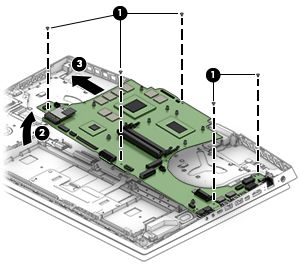
Packaging and transporting guidelines .............................................................................................................. 28
5 Removal and replacement procedures for Customer Self-Repair parts ............................................................. 29
Component replacement procedures .................................................................................................................. 29
Preparation for disassembly ............................................................................................................. 29
Bottom cover ..................................................................................................................................... 30
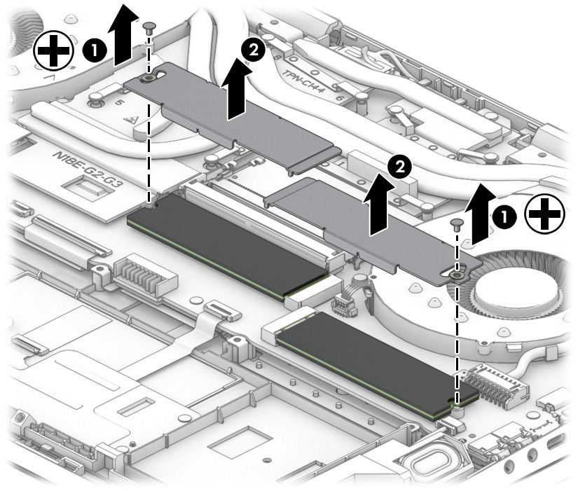
Solid-state drive and Optane memory module ................................................................................ 32
Memory module ................................................................................................................................ 34
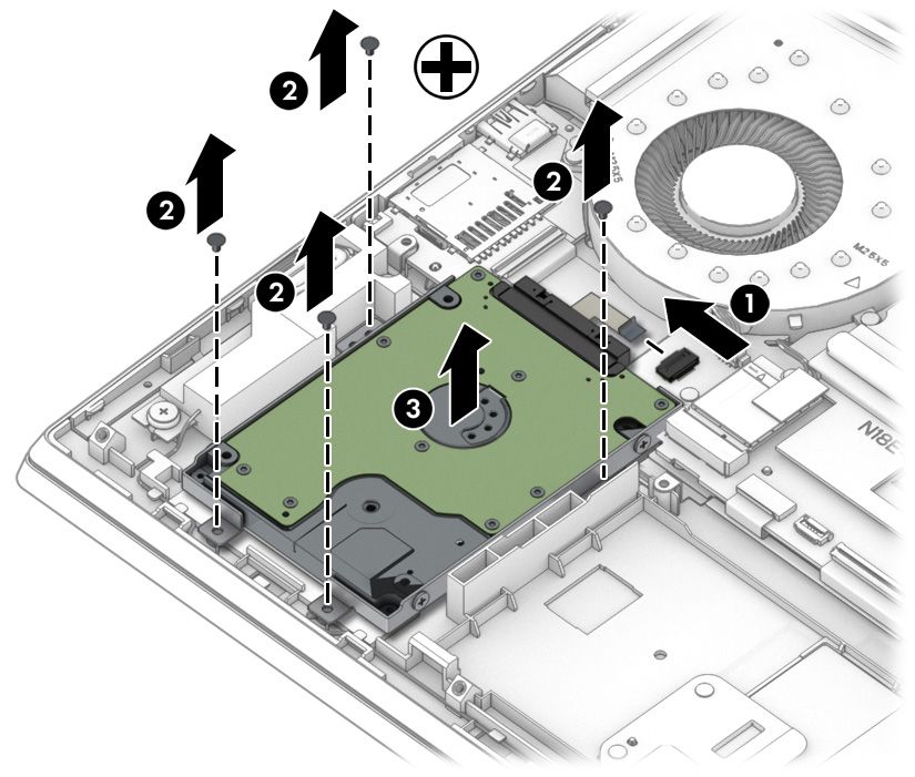
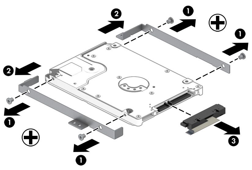
Hard drive assembly .......................................................................................................................... 35
6 Removal and replacement procedures for authorized service provider parts .................................................... 37
Component replacement procedures .................................................................................................................. 37
Thermal material ............................................................................................................................... 37
Battery ............................................................................................................................................... 38
WLAN module .................................................................................................................................... 39
Power connector ............................................................................................................................... 41
Speaker assembly ............................................................................................................................. 42
Touchpad button board ..................................................................................................................... 43
Heat sink/fan assembly .................................................................................................................... 44
Card reader/USB board ...................................................................................................................... 47
Power button board .......................................................................................................................... 48
System board .................................................................................................................................... 49
Thermal sensor board ....................................................................................................................... 51
Display assembly ............................................................................................................................... 52
Keyboard/top cover ........................................................................................................................... 59
7 Using Setup Utility (BIOS) ............................................................................................................................. 60
Starting Setup Utility (BIOS) ................................................................................................................................ 60
Updating Setup Utility (BIOS) .............................................................................................................................. 60
Determining the BIOS version ........................................................................................................... 60
Downloading a BIOS update .............................................................................................................. 61
8 Using HP PC Hardware Diagnostics ................................................................................................................ 62
Using HP PC Hardware Diagnostics Windows (select products only) ................................................................. 62
Downloading HP PC Hardware Diagnostics Windows ....................................................................... 62
Downloading the latest HP PC Hardware Diagnostics Windows version ....................... 63
Downloading HP Hardware Diagnostics Windows by product name or number
(select products only) ..................................................................................................... 63
Installing HP PC Hardware Diagnostics Windows ............................................................................. 63
Using HP PC Hardware Diagnostics UEFI ............................................................................................................. 63
viii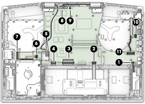
Starting HP PC Hardware Diagnostics UEFI ....................................................................................... 64
                               Downloading HP PC Hardware Diagnostics UEFI to a USB flash drive .............................................. 64
                                                Downloading the latest HP PC Hardware Diagnostics UEFI version .............................. 64
                                                Downloading HP PC Hardware Diagnostics UEFI by product name or number
                                                (select products only) ..................................................................................................... 64
               Using Remote HP PC Hardware Diagnostics UEFI settings (select products only) ............................................. 65
                               Downloading Remote HP PC Hardware Diagnostics UEFI ................................................................. 65
                                                Downloading the latest Remote HP PC Hardware Diagnostics UEFI version ................. 65
                                                Downloading Remote HP PC Hardware Diagnostics UEFI by product name or
                                                number ............................................................................................................................ 65
                               Customizing Remote HP PC Hardware Diagnostics UEFI settings .................................................... 65

9 Backing up, restoring, and recovering ........................................................................................................... 67
               Backing up information and creating recovery media ........................................................................................ 67
                               Using Windows tools ......................................................................................................................... 67
                               Using the HP Cloud Recovery Download Tool to create recovery media (select products only) ..... 67
               Restoring and recovery ........................................................................................................................................ 68
                               Restoring, resetting, and refreshing using Windows tools .............................................................. 68
                               Recovering using HP Recovery media ............................................................................................... 68
                               Changing the computer boot order ................................................................................................... 68

10 Specifications ............................................................................................................................................ 69

11 Power cord set requirements ...................................................................................................................... 70
               Requirements for all countries ............................................................................................................................ 70
               Requirements for specific countries and regions ................................................................................................ 71

12 Recycling .................................................................................................................................................. 73

Index ............................................................................................................................................................. 74

                                                                                                                                                                                         ix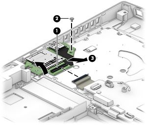
x
1   Product description

    Table 1-1 Product components and their descriptions
    Category                  Description

    Product Name              OMEN by HP 17 Laptop PC

                              Model numbers: 17-cb0000~17-cb0999, 17-cb000

    Processor                 Intel® Core™ i9-9880H (2.3 GHz, turbo up to 4.8 GHz, 2666 MHz FSB, 16 MB L3 cache, eight core, 45 W)

                              Intel Core i7-9750H (2.6 GHz, turbo up to 4.5 GHz, 2666 MHz FSB, 12 MB L3 cache, six core, 45 W)

                              Intel Core i5-9300H (2.4 GHz, turbo up to 4.1 GHz, 2666 MHz FSB, 8 MB L3 cache, quad core, 45 W)

    Graphics                  Internal graphics

                              Intel UHD Graphics 630

                              Discrete graphics

                              NVIDIA® GeForce® RTX 2080 with up to 8 GB of dedicated video memory (N18E-G3)

                              NVIDIA GeForce RTX 2070 with up to 8 GB of dedicated video memory (N18E-G2)

                              NVIDIA GeForce RTX 2060 with up to 6 GB of dedicated video memory (N18E-G0)

                              NVIDIA GeForce GTX 1660Ti with up to 6 GB of dedicated video memory (N18E-G0)

                              NVIDIA GeForce GTX 1650 with up to 4 GB of dedicated video memory (N18P-G0)

                              Supports HD decode, DX12, and HDMI

                              Supports Optimus™

                              Supports GPS (GPU Performance Scaling)

                              Supports VR

                              Supports MR ready

    Display panel             43.9 cm (17.3 in.), full high-definition (FHD) (1920 × 1080), antiglare, 72% CG, WLED, UWVA, slim,
                              narrow bezel, 300 nits; Microsoft® HDR streaming capable

                              eDP 1.2, A/P, 60 Hz

                              eDP 1.4 + PSR, A/P, 144 Hz

                              eDP 1.4 + PSR, 144 Hz

                              eDP 1.4 + PSR2, 60 Hz

    Memory                    Two SODIMM slots, customer accessible/upgradeable

                              DDR4-2666 dual channel support, 1.2 V

                              Supports up to 32 GB maximum system memory in the following configurations:

                              ●    32 GB (16 GB × 2)

                              ●    16 GB (16 GB × 1 or 8 GB × 2)

                              ●    12 GB (8 GB × 1 + 4 GB × 1)

                                                                                                                                     1
Table 1-1 Product components and their descriptions (continued)
Category Description
● 8 GB (8 GB × 1 or 4 GB × 2)
Storage Supports 7.0 mm/7.2 mm, 2.5 in. SATA hard drives
Support for solid-state drive + hard drive
Support for M.2 PCIe/SATA solid-state drive
Accelerometer/hard drive protection support
Single hard drive configurations
1 TB, 7200 rpm, 7.0 mm, 2.5 in.
Dual storage configurations
512 GB, PCIe, NVMe, TLC, solid-state drive + 1 TB, PCIe, NVMe, TLC solid-state drive
512 GB, PCIe, NVMe, TLC, solid-state drive + 1 TB, 7200 rpm hard drive
512 GB, PCIe, NVMe, TLC, x2, RAID 0 solid-state drive + 2 TB, 5400 rpm hard drive
256 GB, PCIe, NVMe, TLC, solid-state drive + 1 TB, 7200 rpm hard drive
256 GB, PCIe, NVMe, TLC, solid-state drive + 2 TB, 5400 rpm hard drive
256 GB, PCIe, NVMe, TLC, x2, RAID 0 solid-state drive + 1 TB, 5400 rpm hard drive
128 GB, PCIe, NVMe, TLC, solid-state drive + 1 TB, 7200 rpm hard drive
NVMe, TLC, M.2 solid-state drive
1 TB, PCIe-3 × 4
512 GB, PCIe-3 × 4
256 GB, PCIe-3 × 4
Intel Optane™ (3D Xpoint) Solution (PCIe) Gen3 × 2 configurations
32 GB (Optane) + 512 GB, PCIe-3 × 2 × 2 solid-state drive
16 GB (Optane) + 1 TB, 7200 rpm hard drive
Audio Audio brand: Bang & Olufsen
Audio control panel: OMEN Audio Control (supports DTS: X Ultra)
Supports HP Audio Boost 2.0 with discrete amplifier
Dual speakers
Supports Headphone X
Video HP Wide Vision HD Camera - indicator LED, USB 2.0, HD BSI sensor, f2.0, WDR, 88° WFOV
720p by 30 frames per second
Dual-array digital microphone with appropriate software: beam forming, echo cancellation, noise
suppression
RJ-45 (network) jack Integrated 10/100/1000 NIC
Supports Network Booster
Sensors Accelerometer
2 Chapter 1 Product descriptionTable 1-1 Product components and their descriptions (continued)
Category Description
Wireless networking Integrated wireless option with dual antennas (M.2/MIPI/BRI)
Intel Wireless-AC 9560 802.11ac 2 × 2 Wi-Fi + Bluetooth® 5 (non-vPro) (MU-MIMO, Gigabit Wi-Fi speeds
supported)
Integrated wireless option with dual antennas (M.2/PCIe)
Intel Wi-Fi 6 AX200 + Bluetooth 5 (802.11ax 2 × 2 vPro, supporting gigabit transfer speeds)
Realtek RTL8822BE 802.11 ac 2 × 2 Wi-Fi + Bluetooth 4.2 Combo Adapter (MU-MIMO supported)
Support for Wi-Fi CERTIFIED Miracast™-certified devices
Ports HP Smart Plug AC adapter
Audio-out (headphone)/Audio-in (microphone) combo jack
Microphone-in jack
RJ-45 (network) jack
High-definition multimedia interface (HDMI) v.2.0 + HDCP 2.2 supporting up to 4096 × 2160 at 60 Hz
Hot plug/unplug and auto detect for correct output to wide-aspect vs. standard aspect video (auto
adjust panel resolution to fit embedded panel and external monitor connected)
Mini DisplayPort™
USB 3.0 Type A ports (3); two on left side, one on right side; supports HP Sleep & Charge (right side)
USB 3.1 Gen 2 Type-C port (left side; supports data transfer, DisplayPort 1.4 output up to 7680 × 3840
[60 Hz]; supports HP Sleep & Charge)
USB 3.1 Gen 2 Type-C port with Thunderbolt™ Gen 3 technology (left side)
Media card reader Supports microSD™/SDHC™/SDXC™
Push-push insertion/removal
Internal card expansion One M.2 slot for WLAN
Two M.2 slots for solid-state drive
Keyboard/pointing devices Keyboard
Full-sized, backlit, island-style, keyboard with numeric keypad, single-zone lighting
Full-sized, backlit, island-style, keyboard with numeric keypad, 4-zone lighting
Special highlight for WASD keys
Supports 26-key RO antighosting keys
Touchpad requirements
Touchpad with image sensor
Multitouch gestures enabled
Support for Precision Touchpad
Support for modern trackpad gestures
Taps enabled as default
Power requirements Battery
3Table 1-1 Product components and their descriptions (continued)
Category Description
Supports a 4 cell, 70 Wh, polymer battery
Supports a 3 cell, 52 Wh, polymer battery
Supports battery life enhancement
Supports battery fast charge (45 minutes, 50% charged)
Smart AC adapter (PFC)
330 W, 7.4 mm
230 W, 7.4 mm
200 W, 4.5 mm
150 W, 4.5 mm
Power cord (1 m, conventional)
C13 (for adapters > 200 W)
C5
Security Trusted Platform Module (fTPM) 2.0, firmware based
Operating system Preinstalled
Windows® 10 Home 64
Windows 10 Home 64 Advanced
Windows 10 Home 64 Advanced Single Language
Windows 10 Home 64 High-End Chinese Market CPPP
Windows 10 Home 64 Plus
Windows 10 Home 64 Plus Single Language
Windows 10 Home 64 Plus Single Language Africa Market
Windows 10 Home 64 Plus Single Language APAC EM PPP
Windows 10 Home 64 Plus Single Language India Market PPP
Windows 10 Home 64 Plus Single Language Indonesia Market PPP
Windows 10 Pro 64
Windows 10 Pro 64 High End
Windows 10 Pro 64 Web/Kiosk
FreeDOS 3.0
Serviceability End-user replaceable parts
AC adapter
Memory modules
Solid-state drive
Hard drive
4 Chapter 1 Product description2 Getting to know your computer
Your computer features top-rated components. This chapter provides details about your components, where
they are located, and how they work.
NOTE: Actual computer color, feature locations, and icon labels may vary from the images depicted.
Right side
Table 2-1 Right-side components and their descriptions
Component Description
(1) Drive light ● Blinking white: The hard drive is being accessed.
● Amber: HP 3D DriveGuard has temporarily parked the hard
drive.
(2) Memory card reader Reads optional memory cards that enable you to store, manage,
share, or access information.
To insert a card:
– or – 1. Hold the card label-side up, with connectors facing the
computer.
2. Insert the card into the memory card reader, and then
press in on the card until it is firmly seated.
To remove a card:
▲ Press in on the card, and then remove it from the memory
card reader.
(3) USB SuperSpeed port with HP Sleep and Charge Connects a USB device, provides high-speed data transfer, and
even when the computer is off, charges most products such as a
cell phone, camera, activity tracker, or smartwatch.
(4) Vent Enables airflow to cool internal components.
NOTE: The computer fan starts up automatically to cool
internal components and prevent overheating. It is normal for
the internal fan to cycle on and off during routine operation.
Right side 5Left side
NOTE: Refer to the illustration that most closely matches your computer.
Table 2-2 Left-side components and their descriptions
Component Description
(1) Power connector Connects an AC adapter.
(2) AC adapter and battery light ● White: The AC adapter is connected and the battery is fully
charged.
● Blinking white: The AC adapter is disconnected and the
battery has reached a low battery level.
● Amber: The AC adapter is connected and the battery is
charging.
● Off: The battery is not charging.
(3) RJ-45 (network) jack/status lights Connects a network cable.
● White: The network is connected.
● Amber: Activity is occurring on the network.
(4) HDMI port Connects an optional video or audio device, such as a high-
definition television, any compatible digital or audio component,
or a high-speed High-Definition Multimedia Interface (HDMI)
device.
(5) Dual-Mode DisplayPort connector Connects an optional digital display device, such as a high-
performance monitor or projector.
(6) USB SuperSpeed ports Connect a USB device, such as a cell phone, camera, activity
tracker, or smartwatch, and provide high-speed data transfer.
(7) USB Type-C port with HP Sleep and Charge Connects a USB device that has a Type-C connector, provides
data transfer, and even when the computer is off, charges most
products such as a cell phone, camera, activity tracker, or
smartwatch.
– and –
Connects a display device that has a USB Type-C connector,
providing DisplayPort output.
NOTE: Cables and/or adapters (purchased separately) may be
required.
(7) USB Type-C power connector and Thunderbolt™ Even when the computer is off, connects and charges most USB
port with HP Sleep and Charge devices that have a Type-C connector, such as a cell phone,
6 Chapter 2 Getting to know your computerTable 2-2 Left-side components and their descriptions (continued)
Component Description
camera, activity tracker, or smartwatch, and provides high-
speed data transfer.
– and –
Connects a display device that has a USB Type-C connector,
providing DisplayPort output.
NOTE: Your computer may also support a Thunderbolt docking
station.
NOTE: Cables and/or adapters (purchased separately) may be
required.
(8) Audio-out (headphone)/Audio-in (microphone) Connects optional powered stereo speakers, headphones,
combo jack earbuds, a headset, or a television audio cable. Also connects an
optional headset microphone. This jack does not support
optional standalone microphones.
WARNING! To reduce the risk of personal injury, adjust the
volume before putting on headphones, earbuds, or a headset.
For additional safety information, see the Regulatory, Safety,
and Environmental Notices.
To access this guide:
▲ Type HP Documentation in the taskbar search box,
and then select HP Documentation.
NOTE: When a device is connected to the jack, the computer
speakers are disabled.
(9) Audio-in (microphone) jack Connects an optional computer headset microphone, stereo
array microphone, or monaural microphone.
Rear
Table 2-3 Rear components and their descriptions
Description
Vents Enable airflow to cool internal components.
NOTE: The computer fan starts up automatically to cool internal
components and prevent overheating. It is normal for the internal fan to
cycle on and off during routine operation.
Rear 7Display
Table 2-4 Display components and their descriptions
Component Description
(1) WLAN antennas* Send and receive wireless signals to communicate with wireless local
area networks (WLANs).
(2) Internal microphones Record sound.
(3) Camera light On: The camera is in use.
(4) Camera Allows you to video chat, record video, and record still images. Some
cameras also allow a facial recognition logon to Windows, instead of
a password logon.
NOTE: Camera functions vary depending on the camera hardware
and software installed on your product.
*The antennas are not visible from the outside of the computer. For optimal transmission, keep the areas immediately around the
antennas free from obstructions.
For wireless regulatory notices, see the section of the Regulatory, Safety, and Environmental Notices that applies to your country or
region.
To access this guide:
▲ Type HP Documentation in the taskbar search box, and then select HP Documentation.
8 Chapter 2 Getting to know your computerKeyboard area
Touchpad
Table 2-5 Touchpad components and their descriptions
Component Description
(1) Touchpad zone Reads your finger gestures to move the pointer or activate items
on the screen.
(2) Left touchpad button Functions like the left button on an external mouse.
(3) Right touchpad button Functions like the right button on an external mouse.
Keyboard area 9Lights
Table 2-6 Lights and their descriptions
Component Description
(1) Power light ● On: The computer is on.
● Blinking: The computer is in the Sleep state, a power-
saving state. The computer shuts off power to the display
and other unneeded components.
● Off: The computer is off or in Hibernation. Hibernation is a
power-saving state that uses the least amount of power.
(2) Caps lock light On: Caps lock is on, which switches the key input to all capital
letters.
(3) Mute light ● On: Computer sound is off.
● Off: Computer sound is on.
(4) Touchpad light ● On: The touchpad is off.
● Off: The touchpad is on.
(5) Num lock light ● On: Num lock is on. When num lock is on, the keypad can
be used like an external numeric keypad.
● Off: Num lock is off.
10 Chapter 2 Getting to know your computerButton
Table 2-7 Button and description
Component Description
(1) Power button ● When the computer is off, press the button to turn on the
computer.
● When the computer is on, press the button briefly to
initiate Sleep.
● When the computer is in the Sleep state, press the button
briefly to exit Sleep (select products only).
● When the computer is in Hibernation, press the button
briefly to exit Hibernation.
CAUTION: Pressing and holding down the power button results
in the loss of unsaved information.
If the computer has stopped responding and shutdown
procedures are ineffective, press and hold the power button
down for at least 5 seconds to turn off the computer.
To learn more about your power settings, see your power
options:
▲ Right-click the Power icon , and then select Power
Options.
Keyboard area 11Special keys
Table 2-8 Special keys and their descriptions
Component Description
(1) Gaming macro keys Allow you to create different gaming key combinations when
used alone or with the fn, ctrl, alt, or shift keys.
NOTE: See HP OMEN Command Center on page 15 for more
information.
(2) esc key Displays system information when pressed in combination with
the fn key.
(3) fn key Executes frequently used system functions when pressed in
combination with the fn key.
(4) Windows key Opens the Start menu.
NOTE: Pressing the Windows key again will close the Start
menu.
(5) Action keys Execute frequently used system functions.
NOTE: On select products, the f5 action key turns the keyboard
backlight feature off or on.
(6) Airplane mode key (also referred to as the Turns the airplane mode and wireless feature on or off.
wireless button)
NOTE: A wireless network must be set up before a wireless
connection is possible.
(7) OMEN key Opens the OMEN Command Center software.
(8) num lk key Alternates between the navigational and numeric functions on
the integrated numeric keypad.
12 Chapter 2 Getting to know your computerBottom
Table 2-9 Bottom components and their descriptions
Component Description
(1) Vent Enables airflow to cool internal components.
NOTE: The computer fan starts up automatically to cool
internal components and prevent overheating. It is normal
for the internal fan to cycle on and off during routine
operation.
(2) Speakers Produce sound.
Bottom 13Labels
The labels affixed to the computer provide information you may need when you troubleshoot system
problems or travel internationally with the computer. Labels may be in paper form or imprinted on the
product.
IMPORTANT: Check the following locations for the labels described in this section: the bottom of the
computer, inside the battery bay, under the service door, on the back of the display, or on the bottom of a
tablet kickstand.
● Service label—Provides important information to identify your computer. When contacting support, you
may be asked for the serial number, the product number, or the model number. Locate this information
before you contact support.
Table 2-10 Service label components
Component
(1) HP product name
(2) Model number
(3) Product ID
(4) Serial number
(5) Warranty period
● Regulatory label(s)—Provide(s) regulatory information about the computer.
● Wireless certification label(s)—Provide(s) information about optional wireless devices and the approval
markings for the countries or regions in which the devices have been approved for use.
14 Chapter 2 Getting to know your computerHP OMEN Command Center
HP OMEN Command Center allows you to customize your computer for your specific gaming needs.
▲ To open HP OMEN Command Center, select the Start button, select HP OMEN Command Center, and
then follow the on-screen instructions.
– or –
Press the OMEN key at the top right side of the keyboard.
The HP OMEN Command Center dashboard provides a central location to access and configure the following
features:
NOTE: Features may vary by platform.
● System Vitals: Monitor the computer status and performance.
● Lighting: Customize the keyboard lighting (select products only).
● Network Booster: View and adjust network priorities and settings.
● Performance Control: Optimize the performance of your computer for the task you are performing.
● Gaming Macro Keys: Configure the P-keys (select products only).
● OMEN Game Stream: Provide the ability to stream games to other devices.
● Update: Update the OMEN Command Center software.
● Help: Access “How to” information and frequently asked questions.
NOTE: To minimize the dashboard, select the < button at the top of the dashboard.
HP OMEN Command Center 153 Illustrated parts catalog
Computer major components
NOTE: HP continually improves and changes product parts. For complete and current information on
supported parts for your computer, go to http://partsurfer.hp.com, select your country or region, and then
follow the on-screen instructions.
NOTE: Details about your computer, including model, serial number, product key, and length of warranty,
are on the service tag at the bottom of your computer. See Labels on page 14 for details.
16 Chapter 3 Illustrated parts catalogTable 3-1 Computer major components and their descriptions
Item Component Spare part number
(1) Display assembly
NOTE: Display assemblies are spared only at a subcomponent level.
(2) Keyboard/top cover (includes acetate tape):
For a detailed list of country codes, see Keyboard/top cover on page 59.
For use models with 1-zone lighting (dragon red legend + red backlight) L57377-xx1
For use models with 4-zone lighting (white legend + RGB backlight) L57378-xx1
For use models with 1-zone lighting (dragon red legend + red backlight) with Thunderbolt L57379-xx1
For use models with 4-zone lighting (white legend + RGB backlight) with Thunderbolt L57380-xx1
For use models with 1-zone lighting (dragon red legend + red backlight) with Thunderbolt (G-sync) L62862-xx1
For use models with 4-zone lighting (white legend + RGB backlight) with Thunderbolt (G-sync) L62863-xx1
(3) Touchpad button board L57343-001
(4) Power button board L57371-001
NOTE: The power button board cable is available as spare part number L57364-001.
(5) Card reader/USB board L57370-001
NOTE: The card reader/USB board cable is available as spare part number L57363-001.
(6) Hard drive
NOTE: The hard drive connector is available as spare part number L57362-001.
2 TB, 5400 rpm 912487-850
1 TB, 7200 rpm 766644-001
(7) Speaker assembly (includes cushion) L57375-001
(8) Battery
4 cell, 70 Wh 917724-855
3 cell, 52 Wh L08855-855
(9) System board (includes processor):
All system boards use the following part numbers:
xxxxxx-001: Non-Windows operating system
xxxxxx-601: Windows 10 operating system
Intel Core i9-9880H processor and 8 GB of discrete graphics memory (GeForce RTX 2080; G-Sync) L59778-xx1
Intel Core i7-9750H processor and 8 GB of discrete graphics memory (GeForce RTX 2080; G-Sync) L59777-xx1
Intel Core i7-9750H processor and 8 GB of discrete graphics memory (GeForce RTX 2070; G-Sync) L59776-xx1
Intel Core i7-9750H processor and 6 GB of discrete graphics memory (GeForce RTX 2060) L59775-xx1
Intel Core i7-9750H processor and 6 GB of discrete graphics memory (GeForce GTX 1660Ti) L59774-xx1
Intel Core i7-9750H processor and 4 GB of discrete graphics memory (GeForce GTX 1650) L59772-xx1
Intel Core i5-9300H processor and 6 GB of discrete graphics memory (GeForce GTX 1660Ti) L59773-xx1
Computer major components 17Table 3-1 Computer major components and their descriptions (continued)
Item Component Spare part number
Intel Core i5-9300H processor and 4 GB of discrete graphics memory (GeForce GTX 1650) L59771-xx1
Thermal pad kit (not illustrated) L57444-001
(10) Solid-state drives (M.2):
1 TB, PCIe, Gen 3 × 4 L57387-001
512 GB, PCIe, Gen 3 × 4 L57386-001
512 GB, PCIe + 32 GB Optane memory L57388-001
256 GB, PCIe, Gen 3 × 4 L57385-001
128 GB, PCIe, Gen 3 × 2 L57384-001
16 GB, PCIe, Gen 3 × 2 Optane memory module L57383-001
(11) WLAN module
Intel Wireless-AC 9560 802.11ac 2 × 2 Wi-Fi + Bluetooth 5 L22634-005
Intel Wi-Fi 6 AX200 802.11ax 2 × 2 + Bluetooth 5 (non-vPro) L35282-005
Realtek RTL8822BE 802.11ac 2 × 2 Wi-Fi + Bluetooth 4.2 Combo Adapter (MU-MIMO supported) 924813-855
(12) Memory modules (DDR4-2666):
16 GB 937438-850
8 GB 937236-850
4 GB L10598-850
(13) Power connector cable
For use in models with N18P-G0 graphics (GeForce GTX 1650; 200 W) L57358-001
For use in models with N18E-G0/G1 graphics (GeForce GTX 1660Ti/RTX 2060; 200 W) L57359-001
For use in models with N18E-G2/G3 graphics (GeForce RTX 2070/2080; 330 W) L60899-001
(14) Heat sink
NOTE: Heat sink appearance may vary.
Heat sink for use in models with GeForce GTX 1650 graphics L57367-001
Heat sink for use in models with GeForce GTX 1660Ti graphics L57366-001
Heat sink for use in models with GeForce RTX 2060 graphics L62864-001
Heat sink for use in models with GeForce RTX 2070 graphics L62865-001
Heat sink for use in models with GeForce RTX 2080 graphics L62866-001
Thermal grease (not illustrated) L65268-001
Thermal pad kit (not illustrated) L57444-001
(15) Thermal sensor board L57372-001
NOTE: The thermal sensor board cable is available as spare part number L57365-001.
(16) Bottom cover
18 Chapter 3 Illustrated parts catalogTable 3-1 Computer major components and their descriptions (continued)
Item Component Spare part number
For use in models with N18P/N18E G0/G1 graphics (NVIDIA GeForce GTX 1650, 1660Ti, RTX 2060) L57356-001
For use in models with N18E G2/G3 graphics (NVIDIA GeForce RTX 2070/2080) L57357-001
Mass storage devices
Table 3-2 Mass storage devices and their descriptions
Item Component Spare part number
(1) Hard drive
2 TB, 5400 rpm 912487-850
1 TB, 7200 rpm 766644-001
(2) Hard drive connector/cable L57362-001
(3) Solid-state drive (M.2)
1 TB, PCIe, Gen 3 × 4 L57387-001
512 GB, PCIe, Gen 3 × 4 L57386-001
512 GB, PCIe + 32 GB Optane memory L57388-001
256 GB, PCIe, Gen 3 × 4 L57385-001
128 GB, PCIe, Gen 3 × 2 L57384-001
16 GB, PCIe, Gen 3 × 2 Optane memory module L57383-001
Mass storage devices 19Display assembly subcomponents
Table 3-3 Display components and their descriptions
Item Component Spare part number
(1) Display bezel with magnet L57354-001
(2) Webcam/microphone module (includes bezel adhesive) L61453-001
(3) Display panel (includes panel adhesive tape and bezel adhesive):
NOTE: Display panel adhesive is available as spare part number L57369-001.
FHD, 60 Hz L57381-001
FHD, 144 Hz L57382-001
(4) Display hinges (left and right; includes bezel adhesive) L57368-001
(5) Display panel/webcam cable (includes display panel adhesive tape and bezel adhesive):
For use in FHD, 60 Hz displays L57360-001
For use in FHD, 144 Hz displays L57361-001
20 Chapter 3 Illustrated parts catalogTable 3-3 Display components and their descriptions (continued)
Item Component Spare part number
(6) Wireless antennas (main and aux; includes bezel adhesive and display panel adhesive tape) L57353-001
(7) Display back cover (includes bezel adhesive and display panel adhesive tape) L57355-001
Cables
Table 3-4 Cables and their descriptions
Item Component Spare part number
(1) Power connector cable
For use in models with N18P-G0 graphics (GeForce GTX 1650; 200 W) L57358-001
For use in models with N18E-G0/G1 graphics (GeForce GTX 1660Ti/RTX 2060; 200 W) L57359-001
For use in models with N18E-G2/G3 graphics (GeForce RTX 2070/2080; 330 W) L60899-001
(2) Hard drive connector/cable L57362-001
(3) Power button board cable L57364-001
(4) Display cable (includes bezel adhesive and display panel adhesive tape)
For use in models with an FHD, 60 Hz display L57360-001
For use in models with an FHD, 144 Hz display L57361-001
(5) Thermal sensor cable L57365-001
(6) Card reader/USB board cable L57363-001
Cables 21Miscellaneous parts
Table 3-5 Miscellaneous parts and their descriptions
Component Spare part number
AC adapter (PFC):
330 W, 7.4 mm 925142-850
230 W, 7.4 mm 925141-850
200 W, 4.5 mm L00818-850
150 W, 4.5 mm L32661-001
Power cord (C5, 1.0 m):
For use in Australia L22327-001
For use in Denmark L22322-001
For use in Europe L22321-001
For use in India L22624-001
For use in Israel L22323-001
For use in Japan L22330-001
For use in North America L22319-001
For use in the People’s Republic of China L21930-001
For use in South Africa L22325-001
For use in South Korea L22328-001
For use in Switzerland L22324-001
For use in Taiwan L22329-001
For use in Thailand L22326-001
For use in the United Kingdom L22320-001
Power cord (C13, 1.0 m):
For use in Australia L22339-001
For use in Denmark L22334-001
For use in Europe L22333-001
For use in India L22343-001
For use in Israel L22335-001
For use in Japan L22344-001
For use in North America L22331-001
For use in the People’s Republic of China L22341-001
For use in South Africa L22337-001
For use in South Korea L22340-001
For use in Switzerland L22336-001
22 Chapter 3 Illustrated parts catalogTable 3-5 Miscellaneous parts and their descriptions (continued)
Component Spare part number
For use in Taiwan L22342-001
For use in Thailand L22338-001
For use in the United Kingdom L22332-001
External optical drive 747080-001
Thermal grease L65268-001
Thermal pad kit L57444-001
HDMI-to-VGA adapter 701943-001
USB-C-to-USB-A adapter 833960-001
Screw Kit L57376-001
Miscellaneous parts 234 Removal and replacement procedures
preliminary requirements
Tools required
You will need the following tools to complete the removal and replacement procedures:
● Non-marking, non-conductive pry tool
● Magnetic Phillips P1 screwdriver
● Tweezers
Service considerations
The following sections include some of the considerations that you must keep in mind during disassembly
and assembly procedures.
NOTE: As you remove each subassembly from the computer, place the subassembly (and all accompanying
screws) away from the work area to prevent damage.
Plastic parts
IMPORTANT: Using excessive force during disassembly and reassembly can damage plastic parts.
Cables and connectors
IMPORTANT: When servicing the computer, be sure that cables are placed in their proper locations during
the reassembly process. Improper cable placement can damage the computer.
Cables must be handled with extreme care to avoid damage. Apply only the tension required to unseat or seat
the cables during removal and insertion. Handle cables by the connector whenever possible. In all cases, avoid
bending, twisting, or tearing cables. Be sure that cables are routed in such a way that they cannot be caught
or snagged by parts being removed or replaced. Handle flex cables with extreme care; these cables tear
easily.
24 Chapter 4 Removal and replacement procedures preliminary requirementsDrive handling
IMPORTANT: Drives are fragile components that must be handled with care. To prevent damage to the
computer, damage to a drive, or loss of information, observe these precautions:
Before removing or inserting a hard drive, shut down the computer. If you are unsure whether the computer is
off or in Hibernation, turn the computer on, and then shut it down through the operating system.
Before handling a drive, be sure that you are discharged of static electricity. While handling a drive, avoid
touching the connector.
Before removing an optical drive, be sure that a disc is not in the drive and be sure that the optical drive tray is
closed.
Handle drives on surfaces covered with at least 2.54 cm (1 inch) of shock-proof foam.
Avoid dropping drives from any height onto any surface.
After removing a hard drive or an optical drive, place it in a static-proof bag.
Avoid exposing an internal hard drive to products that have magnetic fields, such as monitors or speakers.
Avoid exposing a drive to temperature extremes or liquids.
If a drive must be mailed, place the drive in a bubble pack mailer or other suitable form of protective
packaging and label the package “FRAGILE.”
Workstation guidelines
Follow these grounding workstation guidelines:
● Cover the workstation with approved static-shielding material.
● Use a wrist strap connected to a properly grounded work surface and use properly grounded tools and
equipment.
● Use conductive field service tools, such as cutters, screw drivers, and vacuums.
● When fixtures must directly contact dissipative surfaces, use fixtures made only of static-safe materials.
● Keep the work area free of nonconductive materials, such as ordinary plastic assembly aids
and Styrofoam.
● Handle ESD-sensitive components, parts, and assemblies by the case or PCM laminate. Handle these
items only at static-free workstations.
● Avoid contact with pins, leads, or circuitry.
● Turn off power and input signals before inserting or removing connectors or test equipment.
Electrostatic discharge information
A sudden discharge of static electricity from your finger or other conductor can destroy static-sensitive
devices or microcircuitry. Often the spark is neither felt nor heard, but damage occurs. An electronic device
exposed to electrostatic discharge (ESD) might not appear to be affected at all and can work perfectly
throughout a normal cycle. The device might function normally for a while, but it has been degraded in the
internal layers, reducing its life expectancy.
Networks built into many integrated circuits provide some protection, but in many cases, the discharge
contains enough power to alter device parameters or melt silicon junctions.
Electrostatic discharge information 25IMPORTANT: To prevent damage to the device when you are removing or installing internal components,
observe these precautions:
Keep components in their electrostatic-safe containers until you are ready to install them.
Before touching an electronic component, discharge static electricity by using the guidelines described in this
section.
Avoid touching pins, leads, and circuitry. Handle electronic components as little as possible.
If you remove a component, place it in an electrostatic-safe container.
Generating static electricity
Note the following:
● Different activities generate different amounts of static electricity.
● Static electricity increases as humidity decreases.
Table 4-1 Static electricity occurrence based on activity and humidity
Relative humidity
Event 55% 40% 10%
Walking across carpet 7,500 V 15,000 V 35,000 V
Walking across vinyl floor 3,000 V 5,000 V 12,000 V
Motions of bench worker 400 V 800 V 6,000 V
Removing DIPs from plastic tube 400 V 700 V 2,000 V
Removing DIPs from vinyl tray 2,000 V 4,000 V 11,500 V
Removing DIPs from Styrofoam 3,500 V 5,000 V 14,500 V
Removing bubble pack from PCB 7,000 V 20,000 V 26,500 V
Packing PCBs in foam-lined box 5,000 V 11,000 V 21,000 V
Electronic components can be packaged together in plastic tubes, trays, or Styrofoam.
NOTE: As little as 700 V can degrade a product.
Preventing electrostatic damage to equipment
Many electronic components are sensitive to ESD. Circuitry design and structure determine the degree of
sensitivity. The following packaging and grounding precautions are necessary to prevent static electricity
damage to electronic components.
● To avoid hand contact, transport products in static-safe containers such as tubes, bags, or boxes.
● Protect all electrostatic parts and assemblies with conductive or approved containers or packaging.
● Keep electrostatic-sensitive parts in their containers until they arrive at static-free stations.
● Place items on a grounded surface before removing them from their container.
● Always be properly grounded when touching a sensitive component or assembly.
26 Chapter 4 Removal and replacement procedures preliminary requirements● Avoid contact with pins, leads, or circuitry.
● Place reusable electrostatic-sensitive parts from assemblies in protective packaging or conductive
foam.
Personal grounding methods and equipment
Use the following equipment to prevent static electricity damage to electronic components:
● Wrist straps are flexible straps with a maximum of 1 MΩ ±10% resistance in the ground cords. To
provide proper ground, a strap must be worn snug against bare skin. The ground cord must be
connected and fit snugly into the banana plug connector on the grounding mat or workstation.
● Heel straps/Toe straps/Boot straps can be used at standing workstations and are compatible with
most types of shoes or boots. On conductive floors or dissipative floor mats, use them on both feet with
a maximum of 1 MΩ ±10% resistance between the operator and ground.
Table 4-2 Static shielding protection levels
Static shielding protection levels
Method Voltage
Antistatic plastic 1,500
Carbon-loaded plastic 7,500
Metallized laminate 15,000
Grounding the work area
To prevent static damage at the work area, take the following precautions:
● Cover the work surface with approved static-dissipative material. Provide a wrist strap connected to the
work surface and properly grounded tools and equipment.
● Use static-dissipative mats, foot straps, or air ionizers to give added protection.
● Handle electrostatic sensitive components, parts, and assemblies by the case or PCB laminate. Handle
them only at static-free work areas.
● Turn off power and input signals before inserting and removing connectors or test equipment.
● Use fixtures made of static-safe materials when fixtures must directly contact dissipative surfaces.
● Keep work area free of nonconductive materials such as ordinary plastic assembly aids and Styrofoam.
● Use field service tools, such as cutters, screwdrivers, and vacuums, that are conductive.
Recommended materials and equipment
HP recommends the following materials and equipment to prevent static electricity:
● Antistatic tape
● Antistatic smocks, aprons, or sleeve protectors
● Conductive bins and other assembly or soldering aids
● Conductive foam
● Conductive tabletop workstations with ground cord of 1 MΩ ±10% resistance
● Static-dissipative table or floor mats with hard tie to ground
Electrostatic discharge information 27● Field service kits
● Static awareness labels
● Wrist straps and footwear straps providing 1 MΩ ±10% resistance
● Material handling packages
● Conductive plastic bags
● Conductive plastic tubes
● Conductive tote boxes
● Opaque shielding bags
● Transparent metallized shielding bags
● Transparent shielding tubes
Packaging and transporting guidelines
Follow these grounding guidelines when packaging and transporting equipment:
● To avoid hand contact, transport products in static-safe tubes, bags, or boxes.
● Protect ESD-sensitive parts and assemblies with conductive or approved containers or packaging.
● Keep ESD-sensitive parts in their containers until the parts arrive at static-free workstations.
● Place items on a grounded surface before removing items from their containers.
● Always be properly grounded when touching a component or assembly.
● Store reusable ESD-sensitive parts from assemblies in protective packaging or nonconductive foam.
● Use transporters and conveyors made of antistatic belts and roller bushings. Be sure that mechanized
equipment used for moving materials is wired to ground and that proper materials are selected to avoid
static charging. When grounding is not possible, use an ionizer to dissipate electric charges.
28 Chapter 4 Removal and replacement procedures preliminary requirements5 Removal and replacement procedures for
Customer Self-Repair parts
This chapter provides removal and replacement procedures for Customer Self-Repair parts.
NOTE: The Customer Self-Repair program is not available in all locations. Installing a part not supported by
the Customer Self-Repair program may void your warranty. Check your warranty to determine if Customer
Self-Repair is supported in your location.
Component replacement procedures
NOTE: Details about your computer, including model, serial number, product key, and length of warranty,
are on the service tag at the bottom of your computer. See Labels on page 14 for details.
NOTE: HP continually improves and changes product parts. For complete and current information on
supported parts for your computer, go to http://partsurfer.hp.com, select your country or region, and then
follow the on-screen instructions.
There are as many as 20 screws that must be removed, replaced, and/or loosened when servicing Customer
Self-Repair parts. Make special note of each screw size and location during removal and replacement.
Preparation for disassembly
See Removal and replacement procedures preliminary requirements on page 24 for initial safety procedures.
1. Turn off the computer. If you are unsure whether the computer is off or in Hibernation, turn the
computer on, and then shut it down through the operating system.
2. Disconnect the power from the computer by unplugging the power cord from the computer.
3. Disconnect all external devices from the computer.
Component replacement procedures 29You can also read