Falcon Monitoring System - RLE Technologies - User Guide
←
→
Page content transcription
If your browser does not render page correctly, please read the page content below
RLE Technologies
Falcon Monitoring System

                    User Guide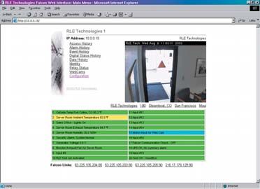
ii

Falcon User Guide
iii

                                         Falcon - Front View

                                          Falcon - Back View

All Falcon units are shipped from the manufacturer with a user guide.

24VDC models are also shipped with a wall adapter.

                                                                        Falcon User Guide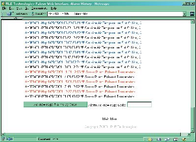
iv

Falcon User Guide
v

Contents                                                                         Product Registration.................................. 36
                                                                                 Flash Program ........................................... 36
Part One - Getting Started ..................................... 8         Part Three - EIA-232 Interface............................. 38
    Chapter One - Product Description ................. 9                      Chapter Five - Start-Up.................................. 39
      Product Description..................................... 9                 Unit Start-Up............................................. 39
      Indicators and Controls - Front Panel .........10                          Flash Executable Code ............................... 40
      Terminal Block Designation .......................11                     Chapter Six - Main Menu ...............................41
      Rear Panel Indicators ................................. 12                 Main Menu.................................................41
      Detailed Switch Settings ............................ 12                 Chapter Seven - Log Menu ............................ 42
    Chapter Two - Falcon Installation.................. 13                       LM - Log Menu ......................................... 42
      Falcon Installation ..................................... 13                 1 - Alarm History Log ............................ 42
      Common Ground Wiring...........................14                            2 - Minute Log........................................ 43
      Sensor Wiring - Interface to Falcon ............15                           3 - Hourly Log ........................................ 43
      Sensor Wiring - Transducer to Falcon.........16                              4 - Daily Log .......................................... 44
      Interface - Falcon Option Cards .................17                          5 - Access Log ......................................... 44
Part Two - Web Interface ......................................18                  6 - Event Log ...........................................45
    Chapter Three - RLE Falcon Main Menu.......19                                  7 - Log Information .................................45
      RLE Falcon Main Menu .............................19                         8 - Digital Status Log.............................. 46
      Access History ........................................... 20                Mx, Hx, Dx, AHCHx............................. 46
      Alarm History ........................................... 20                 RT - Run Times.......................................47
      Event Log ...................................................21              EH, ET, ER, EE, ED ...............................47
      Digital Status Log.......................................21                  20 - Return ............................................. 48
      Log Menu...................................................21            Chapter Eight - System Configuration........... 49
      Minute, Hour, and Day Links ................... 22                         SC - System Configuration ........................ 49
      Identity...................................................... 22            1 - System Menu ..................................... 49
      Relay Status............................................... 22                 1 - System Name.................................. 50
      WebCams.................................................. 23                   2 - Clock.............................................. 50
      Configuration ........................................... 23                   3 - Keypad Access .................................51
    Chapter Four - Configuration Menu ............. 24                                  1 to 20 - Access Codes ......................52
      Configuration Menu ................................. 24                           21 - Exit Request Input .....................53
      Inputs ........................................................ 24                22 - Alarm Bypass Input .................. 54
      Relays ........................................................ 26                23 - Alarm Dial Out .........................55
      System ....................................................... 27                 24 - Return ...................................... 56
      IP Configuration ....................................... 29                    4 - Inputs ............................................. 57
      WebCams.................................................. 29                   5 - Relays ............................................. 59
      Falcon Links.............................................. 30                  6 - Input Power .................................... 59
      Modem...................................................... 30                 7 - Analog Averaging ........................... 60
      Configure Phone Numbers.........................31                             8 - Persistent Traps................................61
      Alarm Settings........................................... 32                   9 - Slave Inputs .................................... 62
      Access Users .............................................. 32                 10 - Slave Relays .................................. 63
      Schedules................................................... 33                11 - Schedules ...................................... 63
      Battery....................................................... 33              12 - BACNet........................................ 64
      EIA-485 .................................................... 34                13 - Exit and Save ................................ 64
      Clock......................................................... 34            2 - IP Configuration Menu ......................65
      E-mail ........................................................35            3 - Modem Configuration Menu .............67
                                                                                        Alarm ID Reference Tables............... 70

                                                                                                                            Falcon User Guide
vi

              4 - EIA-485 Configuration Menu ........... 72
              5 - Factory Menu .....................................74
              6 - Load/Save Config. Data Menu .......... 75
              7 - Configuration Password .....................76
              8 - E-mail, SMTP Menu ......................... 77
              x - Exit .................................................... 77
     Part Four - Remote Access.................................... 78
         Chapter Nine - Configure Remote Access...... 79
     Part Five - PPP Access .......................................... 80
         Chapter Ten - Configure PPP .........................81
     Part Six - Firmware Uploads................................. 82
         Chapter Eleven - Upload via TFTP Client ..... 83
         Chapter Twelve - Upload via EIA-232 Port .... 85
     Appendices........................................................... 86
         Appendix A - Option Card ............................ 87
            Product Codes ........................................... 87
            Installation ................................................ 87
            Convert Input Channels ............................ 87
         Appendix B - Technical Specifications ........... 89
         Appendix C - Falcon 4-20mA Reference ....... 90

Falcon User Guide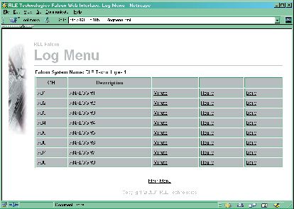
vii

Falcon User Guide
8

                    Part One
                    Getting Started
                    Chapter One.................Product Description......................9
                    Chapter Two .................Installation..................................... 13

Falcon User Guide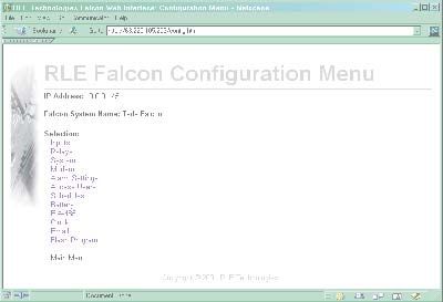
9

Chapter One                                            10BaseT network port, status LEDs, and an interface
                                                       for one option card. The power source for the
Product Description
                                                       standard unit is a 24VDC wall adapter. An optional
                                                       48VDC unit (FMS8-48) is available. Option cards
The Falcon Monitoring System is a comprehensive
                                                       provide additional digital and analog inputs, up to
system which monitors critical operating parameters
                                                       32 per unit. Reference Appendix A for option card
in enterprises, remote network facilities,
                                                       configurations.
communication rooms, remote and unmanned
facilities, and critical support systems. The Falcon
                                                       The Falcon performs internal diagnostics that
is a stand alone system. It operates via embedded
                                                       check the flash program code, serial ports, RAM,
software that handles all data collection, alarm
                                                       non-volatile RAM, real-time clock, internal power
reporting, and multiple concurrent communication
                                                       supplies, relay drivers, analog to digital converter
mediums:
                                                       (ADC), and modem. During operation, the Falcon
                                                       monitors its status and uses several LED indicators
    • The EIA-485 port allows a user to
                                                       to report its condition. The functions of these LEDs
      interconnect five units in a multi-drop
                                                       are described later in this manual.
      topology.
    • The EIA-232 direct connection facilitates
                                                       The embedded Falcon software enables system
      firmware downloads, system configuration,
                                                       configuration, I/O setup, status inquiries, alarm
      inquiries, and alarm reporting.
                                                       reports, data logs, and troubleshooting. Falcon
    • The internal modem provides dial in/out
                                                       software is menu driven and operates with any
      remote access support for the PC interface,
                                                       ASCII terminal or terminal emulation application
      inquiry and alarm reporting, numeric and
                                                       such as HyperTerminal.
      alphanumeric paging, alarm
      acknowledgement, PPP to ISP, e-mail over a
                                                       The universal inputs can be configured for digital
      dial-up connection, and DTMF output relay
                                                       signals - Normally Open (NO) or Normally Closed
      control.
                                                       (NC) dry contacts - or analog signals (4-20mA).
    • The Ethernet 10BaseT network port supports
                                                       The system will report any change of state or
      SNMP V1 MIB for persistent alarm traps,
                                                       values above or below specific set points. Data is
      e-mail alarm delivery, information inquiry,
                                                       logged for all analog points. The high, low, and
      I/O configuration and modification, and
                                                       average readings for each analog point are captured
      alarm acknowledgement. This port also
                                                       in minute, hour, and day logs. Alarms for all
      supports a UDP command set for third-party
                                                       configured points are recorded in the alarm history
      access and development.
                                                       log. All logs are fixed field delimited for easy data
    • BACNet allows the Falcon to communicate
                                                       extraction and upload to other programs. Output
      with building management systems.
                                                       relays can be activated through manual intervention
    • The built-in Web Server enables the Falcon’s
                                                       or triggered by any input. Appropriate time delays
      web interface. This allows the Falcon to be
                                                       can be set for each relay. The Falcon can provide
      configured and its status to be checked from
                                                       24VDC power for external sensors.
      remote locations.
                                                       The Falcon supports a 3x4 numeric keypad interface
The standard Falcon (FMS8) is configured in a rack
                                                       for controlled access to critical areas. Twenty access
mount enclosure with eight universal inputs, two
                                                       codes and descriptions can be entered through the
digital output relays, a keypad interface, a power
                                                       configuration port or over the network via the web
source for external sensors, one EIA-485 port, one
                                                       browser interface. Access is granted when the system
EIA-232 port, one internal modem, one Ethernet
                                                       validates a keypad entry. The system generates an

                                                                                             Falcon User Guide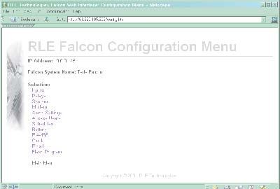
10

     alarm after three invalid entries. Access codes can          which in turn activates an equipment door latch or
     also be entered via telephone using DTMF signaling           electrical lock on an entrance door. An alarm bypass
     – just dial the unit and enter the access code               feature is also provided for doors equipped with a
     followed by the # key. A valid entry activates               forced entry alarming contact.
     an output relay for a user-defined period of time,

     Falcon - Front Panel Indicators and Controls

                            Network LED - Active

                 Network LED - Link                           System Status LED                  Power LED

                                 Communications LED - TX
                                                                                       System Power Switch
                                    Communications LED - RX

                                        Communications LED - OH

                                           Communications LED - CD

     Network LEDs – Two network status LEDs:
        • Link - Green if network link is established, red if not.
        • Active - On (green) when the link is transmitting or receiving data.

     Communications LEDs – Four modem status LEDs:
        • TX - On (green) – Information is being transmitted.
        • RX - On (green) – Information is being received.
        • OH - On (green) – Modem detects a dial tone (off hook).
        • CD - On (yellow) – Carrier detected.

     System Status LED – This LED illuminates (red) during initial boot of the system and flashes ten times per
     second. If the initial boot fails, the LED continues to flash. This indicates a condition that requires service.
     During normal operation, the system status LED turns solid red when the unit is in alarm condition.

     Power LED – On (green) as long as power is on.

     System Power Switch – Used to turn power to the unit on and off.

Falcon User Guide
11
Falcon Terminal Block Designations
TB1 P1 TB2 TB3 TB4 Status TB5 TB6 SW2 P6 P3 P4 Option Card
LEDs
TB1-1 (+) Input for 24/48VDC power TB4-1 Relay 1 normally closed (NC)
TB1-2 (-) Input for 24/48VDC power TB4-2 Relay 1 normally open (NO)
TB4-3 Relay 1 common
P1 24VDC wall adapter input (center +) TB4-4 Relay 2 normally closed (NC)
(not available with 48VDC version) TB4-5 Relay 2 normally open (NO)
TB4-6 Relay 2 common
TB2-1 24VDC positive (+)
(power for sensors) TB5-1 Keypad column 1
TB2-2 24VDC positive (+) TB5-2 Keypad column 2
(power for sensors) TB5-3 Keypad column 3
TB2-3 Channel 1 positive (+) TB5-4 Keypad row 1
TB2-4 Channel 1 negative (-) TB5-5 Keypad row 2
TB2-5 Channel 2 positive (+) TB5-6 Keypad row 3
TB2-6 Channel 2 negative (-) TB5-7 Keypad row 4
TB2-7 Channel 3 positive (+) TB5-8 Unused
TB2-8 Channel 3 negative (-) TB5-9 Input signal normally open (NO)
TB2-9 Channel 4 positive (+) TB5-10 Input signal return
TB2-10 Channel 4 negative (-)
TB6-1 EIA-485 positive (+)
TB3-1 Channel 5 positive (+) TB6-2 EIA-485 negative (-)
TB3-2 Channel 5 negative (-) TB6-3 EIA-485 ground
TB3-3 Channel 6 positive (+)
TB3-4 Channel 6 negative (-) SW2-1 Unit termination switch
TB3-5 Channel 7 positive (+) SW2-2 Master/slave switch
TB3-6 Channel 7 negative (-)
TB3-7 Channel 8 positive (+) P6 EIA-232 female DB9 pin connector
TB3-8 Channel 8 negative (-)
TB3-9 24VDC ground (power for sensors) P3 RJ-11 telephone line connector
TB3-10 24VDC ground (power for sensors)
P4 Ethernet 10BaseT connector
Falcon User Guide12
Falcon Rear Panel Indicators - Relay and Communication Status LEDs
The rear panel of the Falcon houses a series of green LEDs. The chart tracks indicator status when the
corresponding green LED is illuminated:
EIA-232 TX
Status Indicator
K1 EIA-485 TX
K1 output relay Energized
K2 output relay Energized
K3 K5 EIA-232 TX interface Data is being transmitted
EIA-232 RX interface Data is being received
EIA-485 TX interface Data is being transmitted
K4 K6 EIA-485 RX interface Data is being received
K3 to K6 output relays Energized (option card)
Option Card
K2 EIA-485 RX
EIA-232 RX
Base System
Detailed Switch Settings
TB6
EIA-485 SW2
+ - Gnd 1 2
Master Unit #1
Off Switch is on.
On
+ - Gnd 1 2 Switch is off.
Off
Slave Unit #2 On
+ - Gnd 1 2
Off
Slave Unit #3
On
+ - Gnd 1 2
Off
Slave Unit #4
On
+ - Gnd 1 2
Off
Slave Unit #5
On
SW2-1 Termination switch ON (down) for first and last unit wired in the series.
Termination switch OFF (up) for all units between the first and last units wired in the series.
SW2-2 Master/Slave switch OFF (up) for master unit and ON (down) for slave units.
Falcon User Guide13
Chapter Two ii. On the Configuration tab of the
Network screen, double click the
Installation
TCP/IP Ethernet component.
1. The Falcon comes in a 19” rack mount
iii. On the IP Address tab of the
enclosure. Install the Falcon in the rack.
TCP/IP Properties screen, specify the
Use the proper anchoring method to mount
appropriate IP address. Click OK.
the unit securely.
The computer’s IP address has been
changed.
2. Supply either 24VDC or 48VDC to the
unit.
c. Connect the other end of the network
Units have different model numbers. cable to the Ethernet port on the back of
24VDC model: FMS8
the Falcon.
48VDC model: FMS8-48
Verify the model number and power rating (on
back of unit) before applying power. d. Change the IP address of the Falcon to one
provided by the network administrator.
3. The Falcon will not communicate over a This allows the Falcon to communicate on
user’s network the first time it is connected the network.
to the network. The manufacturer programs
the Falcon with a default IP address: e. Change the IP address of the computer
10.0.0.186, subnet: 255.255.255.0. back to its original IP address. If the
This default address must be changed to an computer was configured as DHCP - the
IP address that corresponds with the user’s network domain controller assigns it an IP
network before the Falcon can communicate address, return it to this state.
over the network. .
f. The computer and the Falcon are now
a. Plug the crossover network cable that both configured to communicate on the
shipped with the Falcon unit into the network. Both should be accessible via the
laptop or workstation that will be used network.
to configure the Falcon. This cable is
not intended to be connected to a network 4. The Falcon can be configured through
hub. the web interface or through the EIA-232
interface. To use the web interface, follow the
b. Write down the computer’s IP address. direction in Part Two of this guide. To use
Then change the IP address of the the EIA-232 interface:
computer from its existing address to one
that will allow it to communicate with a. Connect the EIA-232 port on the Falcon
the Falcon, such as 10.0.0.185. It may be to a terminal or PC running terminal
beneficial to set the IP address to one that emulation software (HyperTerminal) with
is one number different from the Falcon’s a 9-Pin Male-Female straight through
IP address. serial cable.
Win95/98/NT directions b. Set the appropriate COM port to 9600
i. Click on Start > Settings > baud, NO parity, 8 data bits,
Control Panel > Network. 1 stop bit, (9600/N/8/1), and
no software or hardware flow
control.
Falcon User Guide14
c. Once the terminal emulation software 5. Connect all other interfaces as required.
starts, press Enter (↵) on the keyboard
and select/execute commands from the 6. Proceed with further configuration and
Main Menu. If the Main Menu does not testing of the unit.
appear, check the communication settings
and make sure the unit is powered on.
Falcon User Guide15
Examples: Sensor Wiring - Interface to Base Falcon
TB2 - Inputs 1 to 4 TB3 - Inputs 5 to 8
24VDC Ch1 Ch2 Ch3 Ch4 Ch5 Ch6 Ch7 Ch8 Gnd
+ + + - + - + - + - + - + - + - + - - -
4 Wire PWR
Analog +
-
Sensor COM
TB2 - Inputs 1 to 4 TB3 - Inputs 5 to 8
24VDC Ch1 Ch2 Ch3 Ch4 Ch5 Ch6 Ch7 Ch8 Gnd
+ + + - + - + - + - + - + - + - + - - -
3 Wire PWR
Analog OUT
Sensor GND
TB2 - Inputs 1 to 4 TB3 - Inputs 5 to 8
24VDC Ch1 Ch2 Ch3 Ch4 Ch5 Ch6 Ch7 Ch8 Gnd
+ + + - + - + - + - + - + - + - + - - -
2 Wire +
Analog
Sensor -
TB2 - Inputs 1 to 4 TB3 - Inputs 5 to 8
24VDC Ch1 Ch2 Ch3 Ch4 Ch5 Ch6 Ch7 Ch8 Gnd
+ + + - + - + - + - + - + - + - + - - -
2 Wire
Dry
Contact
Falcon User Guide16
Sensor Wiring - RLE Transducer to Base Falcon
TB2 - Inputs 1 to 4 TB3 - Inputs 5 to 8
Falcon 24VDC Ch1 Ch2 Ch3 Ch4 Ch5 Ch6 Ch7 Ch8 Gnd
+ + + - + - + - + - + - + - + - + - - -
Temperature: Ch5 (+)
Temperature: Ch5 (-)
Humidity: Ch1 (+)
Humidity: Ch1 (-)
Transducer
Two wire analog sensor with two channels
Falcon User Guide17
Interface - Falcon Option Cards
12 Input Digital Option Card - 12 Input Option Card -
Digital Inputs Output Relays
TB7 TB9
- + - + - + - + - + - +
NC NO C NC NO C
Ch09 Ch10 Ch11 Ch12 Ch13 Ch14 RELAY 3 RELAY 4
Ch15 Ch16 Ch17 Ch18 Ch19 Ch20 RELAY 5 RELAY 6
+ - + - + - + - + - + - NC NO C NC NO C
TB8 TB10
24 Input Digital Option Card - Digital Inputs
TB7 TB9
- + - + - + - + - + - + - + - + - + - + - + - +
Ch09 Ch10 Ch11 Ch12 Ch13 Ch14 Ch21 Ch22 Ch23 Ch24 Ch25 Ch26
Ch15 Ch16 Ch17 Ch18 Ch19 Ch20 Ch27 Ch28 Ch29 Ch30 Ch31 Ch32
+ - + - + - + - + - + - + - + - + - + - + - + -
TB8 TB10
Recommended wiring - RLE Technologies recommends 18 to 20AWG stranded copper for connection from
each monitored point to a terminal block (TB) connection on the Falcon. RLE recommends no more than 500
feet at this specification. If longer runs are needed, please contact RLE Technologies for application guidance.
Shielded twisted pair is recommended for analog signal transmitters being wired outside of conduit runs and
dropped ceiling applications.
Falcon User Guide18
Part Two
Web Interface
Chapter Three ..............Main Menu .................................... 19
Chapter Four ................Configuration Menu .................. 24
Falcon User Guide19
Chapter Three
Main Menu
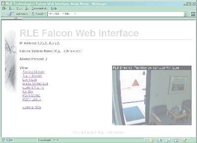
The Falcon’s web interface main menu provides
a convenient way to check the Falcon’s status
and reconfigure basic settings from any
Internet-enabled computer. A click of the
mouse allows users with proper permissions to
view the monitoring system’s output and alter
specific Falcon configuration settings.
The Falcon is shipped to the user with the IP
address configured as 10.0.0.186 and a subnet of
255.255.255.0. The user name is preconfigured
as Falcon. The unit is configured without a
password; when a password is requested, just leave
the space blank. These preconfigurations can be
changed to a personalized IP address, user name,
and password. Do this through the System link on Initial Falcon IP Address
the Configuration Menu of the web interface. Configuration:
Refer to chapter two to learn how to
change the Falcon’s factory assigned IP
To access the Falcon web interface, simply type the
address to one that will enable it to work
IP address of the Falcon into the location bar of the within a user’s network.
web browser. Then enter a user name and password.
The bottom of the Falcon web interface features
Optimize Use of Falcon Web Interface
two columns that list the Falcon’s configured inputs. Netscape’s “Smart Browsing” feature
The number of inputs displayed corresponds with complicates use of the Falcon Web
the number of inputs on the Falcon. Each input Interface. Turn off Smart Browsing to
is numbered. The input’s name is followed by its avoid these complications:
status. • In the menu bar at the top of the
Netscape browser, click on Edit,
The space behind each input is shaded. This then on Preferences.
shading changes as the input’s status changes. This • Smart Browsing is a subcategory
allows users to tell, at a glance, the status of their of the Navigator category. Access
points. Shading is as follows: Smart Browsing and click the box
in front of the “Enable ‘What’s
Green: Input is normal - not in an alarm state.
Related’” option. Eliminate the
Yellow: Analog inputs only - input is in high
check mark to disable this option.
alarm 1 or low alarm 1 state.
Red: Analog input - input is in high alarm 2
or low alarm 2 state.
Digital input - input is in an alarm
state.
Blue: Alarm/Input disabled by a schedule.
Falcon User Guide20
Access History
The Access History link displays the last 100
entries captured by the master unit. The following
information is displayed: access log index (ALxxx),
date and time of event, whether access was granted
or denied, method of entry (keypad or DTFM), and
the description associated with the access code.
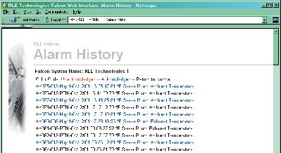
Alarm History
The Alarm History link displays the last 100
alarms captured by the master unit.
The following format is used to record
each alarm entry:
AH###-ID-Condition-Date Time
(Value UOM) Label
AH### is the alarm entry index.
ID is the alarm identifier number.
See Alarm ID Reference Table
Condition is On, High1, High2,
Low1, Low2, or RTN
– Returned To Normal.
Date and Time is the internal date
and time stamp of the alarm
condition.
Label is the alarm descriptor – can be
up to 64 characters long.
Value and Unit of Measure (UOM)
are captured for analog channels only.
The value recorded is the actual analog
value that exceeded its alarm threshold.
Alarms can also be acknowledged from this page.
To do so, type the appropriate code in the box at
the bottom of the page and click the Acknowledge
Alarms by Code button.
Falcon User Guide21
Event Log
The Event Log link displays the past 100 events, as
recorded by the Falcon.
Digital Status Log
A digital input can be configured as NO, NC, or
status. If the digital input is configured as status, it
will not alarm, but it will appear on this page. The
Digital Status Log link displays a history of
the state of digital points configured as status points.
Log Menu
The Log Menu link displays links to the Falcon’s
data logs.
Falcon User Guide22
Minute, Hourly, and Daily Links
The Minute, Hourly, and Daily links on the
Log Menu screen display the detailed information
the Falcon records in its logs.
Identity
The Identity link displays basic Falcon
information, including model number, firmware
version, and IP address.
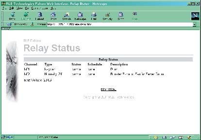
Relay Status
The Relay Status link displays the status of each
Falcon relay output.
Falcon User Guide23
RLE Falcon WebCams
The WebCam link displays a still image (jpg) of all
web cameras linked to the Falcon.
RLE Falcon Configuration
The Configuration link displays a menu that
allows authorized users to configure the Falcon’s
settings. The Configuration Menu is described in
greater detail in the next chapter.
Falcon User Guide24
Chapter Four
Configuration Menu
RLE Falcon Configuration Menu
The Configuration Menu allows authorized users to
adjust the Falcon’s settings. Each link displays a
page with specific configuration settings.
Inputs
The Inputs link allows users to program specific
parameters for each Falcon input. Users must push
the Submit Changes button after they configure
each input. If the changes are not submitted before
proceeding to the next input, all changes will be lost.
The number of inputs varies with installed option
cards.
Per channel, select the appropriate number to modify
inputs and either pick an item from a menu or type
the value or description for the item selected.
Gain and Offset
Gain for 4-20mA Transducer = (Sensor High
Range – Sensor Low Range)/4
Offset for 4-20mA Transducer = Sensor Low
Range – Gain
Relay Control
The table on the next page represents control values
for the Output Control Standard Relays (K1 and
K2) and Optional Relays (K3, K4, K5 and K6).
Select the appropriate value of the relay to activate it,
or add the respective values of the appropriate alarm
condition to activate more than one output relay.
Each input can have individual control values.
Falcon User Guide25
Examples: Relay Alarm Condition Value
K1 High2 Analog Alarm 1
Relay Control: 2 Depending on channel K1 Low2 Analog Alarm 4
configuration, this setting will K1 Digital Alarm 1
activate Output Relay K2 for K2 High2 Analog Alarm 2
either an analog 2nd Stage K2 Low2 Analog Alarm 8
High Alarm or a dry contact K2 Digital Alarm 2
change-of-state. K3 High2 Analog Alarm 16
K3 Low2 Analog Alarm 64
Relay Control: 64 Setting will activate Output K3 Digital Alarm 16
Relay K3 for an analog 2nd K4 High2 Analog Alarm 32
Stage Low Alarm. K4 Low2 Analog Alarm 128
K4 Digital Alarm 32
Relay Control: 35 Depending on channel K5 High2 Analog Alarm 256
configuration, this setting will K5 Low2 Analog Alarm 1024
activate Output Relays K1, K5 Digital Alarm 256
K2, and K4 for either an K6 High2 Analog Alarm 512
analog 2nd Stage High Alarm K6 Low2 Analog Alarm 2048
or a dry contact change-of- K6 Digital Alarm 512
state (1+2+32).
sensor must register 76°F before the Falcon reports it
Relay Control: 10 Setting will activate Output as returned to normal.
Relay K2 for either an analog
Alarm Dial Out is the order in which the Falcon
2nd Stage High or 2nd Stage
Low Alarm (8+2). sends alarm notification. The numbers correspond
to phone numbers configured from the Config
Phone Number links at the bottom of the Modem
Relay Control: 76 Setting will activate Output
Configuration page.
Relays K1, K2, and K3 for an
analog 2nd Stage Low Alarm
BACnet Instance is a BACnet object identifier.
(4+8+64).
It is a numerical code used to identify the input.
Unit of Measure is the appropriate unit of This code must be unique within the BACnet
measure for that input. device. Refer to the BACnet standard for further
information.
Label is the appropriate label for the particular
input. BACnet Unit is the BACnet engineering units.
This represents the units of measurement for the
Alarm Delay is the amount of time the Falcon input. Refer to the BACnet standard for further
waits to send an alert after an alarm condition is information.
detected.
Label (Dig off) is the label that is associated
Hysteresis is a number that designates the with a digital input when it is in an off state. When
amount an input reading must sway from its preset the digital input is in the on state, this label is used.
alarm reading before it is classified as returned to
normal. For example, a temperature sensor alarms
when it reaches 80°F. If hysteresis is set at four, the
Falcon User Guide26
Relays
The Relays link displays a screen that configures
the Falcon’s output relays.
Select a type for each relay. The time field then
designates the number of seconds the relay is active:
timed control 30=30 seconds, -1 = continuous,
following the alarm input.
Label is the appropriate label for the particular
relay.
BACnet Instance is a BACnet object identifier.
It is a numerical code used to identify the input.
This code must be unique within the BACnet
device. Refer to the BACnet standard for further
information.
BACnet Unit is the BACnet engineering units.
This represents the units of measurement for the
input. Refer to the BACnet standard for further
information.
Schedule designates which of the schedules from
the Schedule Configuration menu the relay
will adhere to.
Again, the Submit Changes button must be
pressed once changes are complete, or all changes
will be lost.
Falcon User Guide27
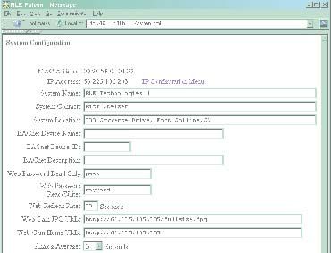
System
The System link allows users to configure basic
Falcon information. The Falcon’s IP address may
also be changed from this page.
System Name is the name of the Falcon.
System Contact is a contact person for the Falcon
unit.
System Location is the physical location of the
Falcon.
BACnet Device Name is similar to the
System Name but is bound by some BACnet
standards. Refer to the BACnet standard for further
information.
BACnet Device ID is similar to the BACnet
Instance but it applies to the entire device. Refer
to the BACnet standard for further information.
BACnet Description is similar to the system
description, but has some limitations. Refer to the
BACnet standard for further information.
To enable the SNMP receiving stations,
Web User Id is falcon (default). This Id can be the Falcon MIB, provided on a diskette
changed allowing up to 18 characters. with every unit, must be loaded on a
system(s) running a Network Operating
Web Password Read Only allows users to access System (NOS). This MIB is compiled
the Falcon web interface. through standard functions of the NOS.
Consult with the Network Administrator for
Web Password Read/Write allows users proper installation of the Falcon MIB on the
to access the Falcon web interface and web NOS. Once the MIB is loaded, the Falcon
configuration screens. unit(s) can be discovered and configured
over the network. For proper operation,
the IP addresses configured in the Falcon
Web Refresh Rate is the rate at which the
communities must match the IP addresses
Falcon’s web pages refresh themselves within the web on the receiving stations.
browser.
Analog Average allows the user to change the
averaging method for analog inputs. Normally,
the system samples analog points once a second
while keeping track of high and low values for each
analog point. After sixty seconds, the average of
these readings and the high and low values for these
Falcon User Guide28
points are recorded in the minute log. To alter this preferred, the Falcon can send only the label on
method of averaging, change the value to one of the Analog traps.
values listed in the drop down menu. Zero or one
maintains the method described above; a higher Falcon Trap Types is set by default to send an
value changes the method of averaging and the alarm entry added type trap. The Trap type can be
manner by which high and low values are recorded. set to a Port Type Trap.
An example of how averaging is altered and how it Communities identify computers that receive
impacts high and low recordings is shown here. SNMP traps from the Falcon and interact with the
• Analog averaging value is set to 5. Falcon over the network. To add a computer to
• The analog point is a temperature sensor. the communities list, select a community number
• Temperature readings are displayed for an posted as “empty.” Enter the receiving computer’s
eleven second period: IP address and a string that identifies
the computer. An IP address of 0.0.0.0 in the
Under normal conditions, the average reading would Communities > IP Address field allows any
equal 71, the high value would equal 74, and the low computer to access the Falcon through an MIB
value would equal 70. By changing the averaging browser or RLENet. Check the box next to write
70,70,70,71,71,72,72,73,73,74,74 if the machine will have read/write network access
Average = 70, High Value = 70, Low Value = 70 - this allows the computer to be configured over
70,70,70,71,71,72,72,73,73,74,74 the network. Check the box next to traps if the
Average = 70, High Value = 70, Low Value = 70 computer will receive traps.
70,70,70,71,71,72,72,73,73,74,74
Average = 71, High Value = 71, Low Value = 70 Changes will not go into effect until the Submit
Changes button is clicked.
70,70,70,71,71,72,72,73,73,74,74
Average = 71, High Value = 71, Low Value = 70
70,70,70,71,71,72,72,73,73,74,74
Average = 72, High Value = 72, Low Value = 70
70,70,70,71,71,72,72,73,73,74,74
Average = 72, High Value = 72, Low Value = 70
70,70,70,71,71,72,72,73,73,74,74
Average = 73, High Value = 73, Low Value = 70
method, the average reading ends up at 73, the
high value at 73, and the low value for this example
remains the same. In a sense, averaging slows down
the sensor response and the rate of change. This
parameter impacts all analog points.
Persistent Traps enables the Falcon to issue
continuous SNMP alarm traps until an Alarm
Acknowledgement is received by the Falcon. The
parameter is a user-defined time interval that is set
in minutes.
Analog Trap Varbinds is for communication
to a NMS via the SNMP traps. The default will
add the value/UOM (unit of measure)/label. If
Falcon User Guide29
IP Configuration
The IP Configuration link allows users to
change the Falcon’s IP address.
Contact a network administrator to obtain a valid IP
address for the network. Then, type the appropriate
IP address, net mask (subnet), and default route into
the interface.
HTTP Port
The Falcon broadcasts its web pages on port: 80 of
the IP address assigned. A zero in the field block
defaults the Falcon to Port: 80. This can be changed
to a specific port allowing increased security of the
web page broadcast.
TCP Max Segment Size 1436 or 536
The Falcon is defaulted to send web pages at a 1436
TCP seg. size. A smaller TCP seg. size helps with a
conjested network.
Refer to Part Five of this User Guide to learn more
about PPP and establishing a PPP connection with
the Falcon.
Changes will not go into effect until the Submit
Changes button is clicked.
WebCams
The WebCam Configuration link allows up to
five IP addressable web cameras to be linked to the
Falcon.
The first field, Web Cam #x JPG URL will display a
still image (jpg) on the main page of the Falcon.
The second field, Web Cam #x Home URL will
open a second window and give the PC a direct link
to the WebCam allowing streaming video to be
displays.
The third field, Web Cam #x Link Test will display
the name assigned to the image..
Falcon User Guide30
Falcon Links
The Falcon Links link allows up to four
Falcons or IP addressable devices to link to the
Falcon.
Modem
The Modem link allows users to configure the
Falcon’s internal modem. The initialization string
can be a maximum of 38 characters. &c1 and &d3
are mandatory. s0=1 sets the modem to answer
after one ring.
The dial prefix should be a specific Hayes
compatible command or dial modifier. It is also
limited to 38 characters. The default is set to atdt.
Pager Deliveries designates the number
of times to call the pager until the alarm is
acknowledged - 1 to 255. Pagers are called in
sequence. For example, if Pager Deliveries is
set to 3 and pagers 1, 7, and 10 are programmed to
be notified, the Falcon dials 1, 7, 10, 1, 7, 10, 1,
7, 10. As soon as the alarm is acknowledged, the
Falcon quits dialing the pagers with that particular
access code. Pagers with different access codes are
still dialed.
Pager Interval allots the number of minutes to Redial Attempts sets a number of times to call a
wait between redials. number until the call is successful, from one to 255.
Pager No Ack Alarm establishes a number to Redial Interval establishes the number of
call if the alarm isn’t acknowledged. A numbered minutes to wait between redials, from one to 255.
contact (one through 16) designates the number to
call. Comm Check Phone defines a numbered contact
(one through 16) to call to check communications.
Pager Baud Rate designates the pager baud rate.
Comm Check Time sets a time (24 hour format) to
Pager Unsuccessful Traps will allow the make the communications check.
Falcon to send an SNMP trap to the NMS if set to
YES. Force Alarm Acknowledge Code acknowledges
all unacknowledged alarms. This acts as a master
Pager Resend will send all unacknowledged code and can override all other alarm acknowledge
alarms in the Alarm History menu if set to YES. codes.
It will only send the last unacknowledged alarm if
set at NO. Changes will not go into effect until the Submit
Changes button is clicked.
Modem Password defines a remote access
password, seven characters max.
Falcon User Guide31
Configure Phone Numbers
This page is accessed through the Config Phone
Number link at the bottom of the Modem
Configuration page. This screen allows users to
configure pager and cell phone numbers that are
used for alarm notification.
A drop down menu allows the user to select
which type of device the Falcon calls. Use the
text option to dial a PC receiving ASCII strings.
Alpha-numeric Pager dials an alphanumeric
pager. Numeric Pager dials a numeric pager.
FalconView dials a PC running FalconView
software.
The Number blank is filled in with the pager service
number for numeric and alphanumeric pager entries.
Each comma after the pager number represents a two
second delay. This delay is used to allow enough
time for the pager service to answer before requesting
the pager ID. Experimentation with the proper Each paging service interprets * and #
number of commas may be necessary. differently. Before using these characters,
consult the paging service to see how they are
The Pager ID field is mandatory for numeric and interpreted and when they should be used.
alphanumeric pagers. An effective numeric page depends largely on
Alphanumeric pager - This ID is sent to the the parameters established by the paging service.
paging service along with all queued alarm Experimentation may be required to achieve desired
messages. The ID is the unique PIN for a results.
specific pager. The ID may be a maximum of
16 characters. The Acknowledgement Code is any number, up
to six digits, used to acknowledge receipt of an alarm
Numeric pager - The ID may be configured to and to terminate any additional call outs for this
deliver different numeric messages. The ID can phone number.
contain 15 characters: any combination of the
numerals 0 through 9 and a * or #. These are Dial Back on Returns designates whether
the only characters that will be transmitted to to call this number again once the alarm condition
the paging service. returns to normal.
A $ can be added or inserted anywhere into the Changes will not go into effect until the Submit
message string. This is converted into a 5 digit Changes button is clicked.
alarm code: XYZZZ.
X - binary alarm condition: 1=on, 0=return to Acknowledge an Alarm:
normal (RTN) 1. Dial Falcon from any phone.
Y - multi-drop address of the Falcon (0-4) 2. Wait for the computer tone.
ZZZ - alarm ID number - see reference table 3. Enter acknowledgement code followed
by the # key.
Falcon User Guide32
Alarm Settings
The Alarm Settings link displays a menu that
allows users to acknowledge current Falcon alarms
and clear the Falcon’s alarm and access history. A
click of each of these buttons will complete the tasks.
Access Users
The Access Users link displays a screen that
allows configuration of a maximum of 20 access
codes and user names. The access code can be up
to six digits long and the user name up to twenty
characters long.
Exit Request and Alarm Bypass Inputs
may also be configured from this menu. Exit
request devices provide a dry contact interface which
signals a request-to-exit relay to unlock a door. The
alarm bypass input is used in conjunction with the
controlled access function of the Falcon. When
enabled, the alarm circuit on the door is bypassed
upon entry of this valid access code.
Press the Submit Changes button after
configuration is complete or all access user
configuration changes will be lost.
Falcon User Guide33
Schedules
The Schedules link allows users to schedule the
activation and deactivation of relay outputs. This
is useful for cycling redundant equipment such as
chillers, generators, etc.
Press the Submit Changes button when done to
save all schedule changes.
Battery
The Battery link is used to configure power when
the Falcon is running off a 48V battery string.
Press the Submit Changes button when done to
save all battery configuration changes.
Falcon User Guide34
EIA-485
The EIA-485 link is used to create polling addresses
for Falcon units wired in series on the EIA-485 bus,
as well as the communications baud rate for the bus.
Before entering addresses, be sure each unit’s SW2
is set properly. Each poll address must be a unique
number from 2 through 254. They are entered
sequentially, separated by commas.
9600 is the default baud rate setting.
Alarm Dial Out specifies which of the
pre-programmed phone numbers to dial if a
communications loss occurs, and in which sequence
to call them.
Press the Submit Changes button when done to
save all schedule changes.
Clock
The Clock link allows users to set the date and time
on the Falcon’s internal clock.
Press the Submit Changes button when done to
save all schedule changes.
Falcon User Guide35
Email
Falcon firmware versions 5.3 and above can send e-
mail messages over a network connection or through
a dial-up connection to an ISP. The Email link
allows users to configure the Falcon so it sends alarm
notifications via e-mail. The Falcon will send one
e-mail message per alarm instance to a maximum
of eight e-mail recipients. This allows the Falcon to
send e-mail messages when inputs are in alarm state.
The Email link displays a data entry form which is
used to configure the e-mail settings.
• Access Type specifies to send the message
through a local network or over a PPP dial up
connection.
• DUN User Name and Password are only
used if PPP is selected. Use these blanks to
specify the dial-up networking user name
and password. Contact your ISP for this • Up to eight e-mail recipients can be specified
information. in the Mail Recipient (1) through
Mail Recipient (8) fields.
• DUN Phone Number is the number the
Falcon dials to connect to the ISP. Contact • SMTP Authentication is used for ESMTP.
your IT Department to obtain this phone Do not change from the default setting unless
number. instructed by your IT Department.
• DNS Servers are provided by your ISP. This When the information is complete, click Submit
information is needed to deliver the e-mail Changes for the changes to take effect.
message.
An individual e-mail client can be configured to
• The Mail (SMTP) Server specifies the enhance the capabilities of the Falcon. The e-mail
e-mail server used to receive/send mail. client can be set up to filter e-mails from specific
Falcons and automatically place the e-mails into
• The Mail Sender Address is the address specific folders. Some e-mail clients can also be
that will be displayed in the form field of the set up to automatically forward the e-mail to other
e-mail messages. recipients.
• The Mail Subject is displayed in the
subject field of the received e-mails. Adding
&m inserts the MAC Address of the Falcon
into the e-mail subject line. This ensures the
e-mail subject is always unique to a Falcon.
Falcon User Guide36
Flash Program
The Flash Program link specifies which versions
of Falcon firmware are loaded onto the Falcon. Only
two copies can be loaded onto the Falcon at a time.
In order to upload a program update, the backup
flash must be blank. If it is not, click the Erase
Backup button to erase it. This erases the oldest
version of firmware stored on the Falcon. Using a
TFTP client software program, send the falcon(vx.x
bx).bin file to the IP address of the Falcon. The
Falcon verifies the file name starts with falcon and
ends with .bin. Other file names or types will
not be accepted. The Falcon will accept TFTP block
sizes of 64, 128, 256, 512, or 1024.
Once the program has been successfully uploaded,
the Falcon will automatically reboot.
Product Registration
The Product Registration link allows the
Falcon to be registered on RLE’s database at the
time of configuration. IP address, subnet makst and
default gateway must already be set on the Falcon
before this link will work.
Falcon User Guide37 Falcon User Guide
38

                    Part Three
                    EIA-232 Interface
                    Chapter Five .................Start Up........................................... 39
                    Chapter Six....................Main Menu .................................... 41
                    Chapter Seven .............Log Menu....................................... 42
                    Chapter Eight...............System Configuration................ 49

Falcon User Guide
39
Chapter Five Falcon V6.1 BOOTUP
Start Up uP last reset by: external signal
Identifying Flash #1
Flash Mfg: 0089 Intel
In order to proceed through this part of Device Id: Mfg: 4471 28F400-B
the Falcon User Guide, the Falcon must Identifying Flash #2
be connected to a PC via the EIA-232 port. If Flash Mfg: 0089 Intel
the Falcon is not yet connected to a PC, turn Device Id: Mfg: 4471 28F400-B
to section 1.2 in this manual and follow the Current Time: MON 10/29/01 15:36:10
directions to do so. Diagnostics in progress
Serials: Passed
Ram: Passed
Unit Start-Up Clock: Passed
When the unit is powered up, diagnostic tests are Nvram: Passed
Flash #1 Blank Check:
performed and the flash program code is verified.
Parm1= Has Data
The main system code is executed after a ten second Parm2= Has Data
delay. During the bootup sequence, the System Boot = Blank
Status LED will flash at a rapid rate of 10 flashes Prgm = Has Data
per second. If the System Status LED continues to Flash Checksum - Calc: 9FC7 Actual:9FC7
flash for more then ten seconds, there is a fault with CS: Valid Serial Num: 0000
Flash #2 Blank Check:
the unit and service is required. Output similar to
Parm3= Blank
the screen shown should appear on the terminal or Parm4= Blank
terminal emulation software. Boot = Blank
Prgm = Has Data
Flash Checksum - Calc: 9FC7 Actual:9FC7
CS: Valid Serial Num: 0001
Relay Driver: Passed
Power Supplies:
24V: 25.62
Passed
ADC MAX197: (0,0,0,0,0,0,0,0) Passed
NIC 83902: Passed
Testing Modem:
ç{24}G{0}ðÆ{0}at{13}{13}{10}OK{13}{10}
Passed
Testing Option Card
Option Card Detected - 12DI/4 (00000001)
Flash Code will start in 10 seconds
Press to abort Flash Code
Checking fl ash program 1 .. Checking fl ash program 2
.. Running fl ash program 2
Falcon User Guide40
Flash Executable Code System Bootup
After the bootup sequence, the main program Falcon8 V6.3 B6 08/24/01
executes from Flash memory. In order to run Current time: 10/29/01 15:36:42
properly, the unit must have a unique MAC
Copyright 2000, Raymond & Lae Engineering Inc.
address (assigned by the manufacturer) and an IP
address. The factory default for the IP address
NvRam Initialized @ 00040000
is 10.0.0.186. If the unit is connected to the Initializing log @ 00048000
enterprise’s network, an IP address must be obtained Loading Block 1
from the network administrator. The Falcon must DATA LOADED
be reconfigured with this new IP address. This This device is an EIA-485 Master
Option Card Detected - 12DI/4
reconfiguration can be done in the field - see the
PC Ethernet address = 00:90:5B:00:00:40
Main Configuration Menu, menu number 2.
IP address = 10.0.0.128
Cold Start Completed
Once the system reaches this point, press the Enter
(↵) key to display the System Main Menu.
Refer to the other chapters in Part Three for setup,
configuration, and display of system information.
Falcon User Guide41
Chapter Six ** System Menu/Help **
Main Menu SS - System Status
CA - Current Alarms
KA - Kill All Alarms
All system functions begin in the Main Menu. Two LM - Log Menu
letter commands display information, execute commands, TI - Display Date/Time
and display submenus for additional inquiry and system AD - ADC Input Values
configuration functions. MS - Modem Stats
NS - Network Stats
AT - Arp Table
SS – System Status
SC - System Config
SS displays the raw input voltage or current of each DU - Dump Network Packets
channel to the Falcon and the alarm status of all input NT - Network Trace
channels and output relays. Actual data displayed PING - Ping an IP Address
depends on option card installed. EX - Exit to Bootloader
Menu Time-Outs
CA – Current Alarms
The Falcon backs up one menu level at a time
CA displays all active alarms on the master unit. If after one minute of inactivity. The process
alarms are present, the System Status LED is red. executes until the Main Menu is reached.
KA – Kill Alarms DU dumps the headers of all network packets received and
KA acknowledges all alarms and terminates all dial-out sent. It is only active until the next command is entered.
communications and network traps. This item is for network debugging only and is not
normally enabled.
LM - Log Menu
LM displays a submenu that lists all the options available NT – Network Trace
for viewing and erasing log files. NT displays troubleshooting messages during the
processing of network packets. It is only active until
TI – Display Date/Time the next command is entered. NT is for network
TI displays the Falcon’s current time and date. troubleshooting only and is not normally enabled.
AD – ADC Input Values PING - Allows user to ping another device on the
AD allows the user to examine the readings of the 4- network.
20mA inputs. These readings can be referenced during
start-up to verify gain and offset calculations. Data EX – Exit to Bootloader
displayed depends on the option card installed. EX is used to enter the Bootloader command section.
The unit will stop monitoring the inputs and allow
MS – Modem Statistics firmware updates to be loaded. To restore normal
MS provides a summary of all modem information. operation after updating firmware, type run and press the
Enter (↵) key on the keyboard, or power the unit
NS – Network Statistics OFF and then back ON again.
NS displays network and EIA-485 statistics including: The Bootloader section is designed
network packets received, packets transmitted, and errors. for experienced technicians or users
responsible for maintaining the system. Exit
SC - System Configuration immediately if you have not been trained in
SC displays a submenu that lists all items for system setup the use of the Bootloader commands.
and configuration.
Contact RLE for more information regarding
DU – Dump Network Packets the commands in this section.
Falcon User Guide42
Chapter Seven ** System Menu/Help **
Log Menu Enter Menu
SS - System Selection > LM
Status
** Log Menu
CA - Current **
Alarms
1. Alarm
KA - Kill History Log
All Alarms
LM – Log Menu 2. Minute
LM - Log Menu Log
LM displays a submenu that lists all the options 3. Hourly
TI - Display Log
Date/Time
available for viewing and erasing log files. 4. Daily
AD - ADC Input Log
Values
Information contained in the logs is fixed field 5. Access
MS - Modem Stats Log
6. Event
NS - Network Log
Stats
delimited for capture and extraction to other
7. Log
AT - Arp Information
Table
software packages. The next few pages show
8. Digital
SC - System ConfigStatus Log
examples of what the commands in this submenu Mx. Minute
DU - Dump NetworkLog by Channel Number (x)
Packets
display. Hx. Hourly
NT - Network Log by Channel Number (x)
Trace
Dx.
PING - Daily
Ping LogAddress
an IP by Channel Number (x)
AHCHx.
EX - Exit to Alarms by Channel Number (x)
Bootloader
RT. Run Times
EH. Erase Alarm History Log
ET. Erase Trending Log
EA. Erase Access Log
ER. Erase Run Times
EE. Erase Event Log
ED. Erase Digital Status Log
20. Return
Enter Menu Selection >
1 - Alarm History Log ** System Menu/Help **
This log contains the last 100 alarms captured by the Enter Menu
SS - System Selection >LM
Status
Master Unit. The following format is used to record Enter
** Log
CA - Current MenuMenu
** Selection >1
Alarms
each alarm entry: KA - Kill AH008-101-On
1. Alarm History -11/01/00
All Alarms Log 12:29:53 Slave Ofl n
AH009-101-On
2. Minute
LM - Log Menu Log -11/01/00 18:12:22 Slave Ofl n
AH###-ID-Condition-Date Time (Value
AH010-101-On
3. Hourly
TI - Display Log
Date/Time -11/01/00 18:12:24 Slave Ofl n
UOM) Label
AH011-101-On
4. Daily
AD - ADC Input Log
Values -11/01/00 18:12:27 Slave Ofl n
AH### is the alarm entry index. AH012-101-On
5. Access
MS - Modem Stats Log -11/01/00 18:12:30 Slave Ofl n
ID is the alarm identifier number. See AH013-101-On
6. Event
NS - Network Log
Stats -11/02/00 15:53:51 Slave Ofl n
Alarm ID Reference Table AH014-101-On
7. Log
AT - Arp Table -11/02/00 15:53:53 Slave Ofl n
Information
Condition is On, High1, High2, Low1, AH015-101-On
ConfigStatus -11/02/00
8. Digital
SC - System Log 15:53:56 Slave Ofl n
AH016-101-On
Mx. Minute
DU - Dump NetworkLog by -11/02/00
Packets 15:53:59
Channel Number Slave Ofl n
(x)
Low2, or RTN – Returned To
Press
Hx. Hourly
NT - Network Enter
Log bytoChannel
Trace Redisplay the (x)
Number Menu
Normal.
Dx.
PING - Number (x)
by Channel
Address
Date and Time is the internal date and time AHCHx.
EX - Exit to Alarms by Channel Number (x)
Bootloader
stamp of the alarm condition. RT. Run Times
Label is the alarm descriptor – can be up to EH. Erase Alarm History Log
64 characters long. ET. Erase Trending Log
EA. Erase Access Log
Value and Unit of Measure (UOM) are
ER. Erase Run Times
captured for analog channels only. The
EE. Erase Event Log
value recorded is the actual analog value that ED. Erase Digital Status Log
exceeded its alarm threshold. 20. Return
Enter Menu Selection >
Falcon User Guide43
2 - Minute Log ** System Menu/Help **
The Minute Log contains the average, high, and low Enter Menu
SS - System Selection >LM
Status
values for all analog inputs in the Master Unit for a Enter
** Log
CA - Current MenuMenu
** Selection >2
Alarms
sixty-minute period. At the end of this period, the “MAC=00:00:6C:22:01:01”
1. Alarm
KA - Kill History Log
All Alarms
“Computer
2. Menu
LM - Log Minute Log Room Falcon”
average, high, and low value for each analog point is
12/01/00
3. Hourly
TI - Display Log11:25
Date/Time
recorded in the Hourly Log, and the Minute Log is
CH01 Values
4. Input
AD - ADC Daily 32
Log 33 32 F Outside Air
reset to accumulate another sixty minutes of activity. MS - ModemCH02
5. Access 68
Stats Log 69 68 F Inside Temp
CH04Stats
6. Event
NS - Network 72
Log 72 72 F Server Room
CH05Information
7. Table
AT - Arp Log 18 19 17 %RH Server Rm
CH07
Config 0
8. Digital
SC - System Status0 Log 0 Volts Generator
DU - Dump 12/01/00
Mx. Minute
NetworkLog11:26
by Channel Number (x)
Packets
CH01Trace
Hx. Hourly
NT - Network 32 by 33
Log 32 Number
Channel F Outside
(x) Air
PING -Dx. CH02
Daily
Ping Log
an IP 68 69
by Channel
Address 68Number
F Inside
(x) Temp
CH04
AHCHx.
EX - Exit 71 by Channel
to Alarms
Bootloader72 71Number
F Server
(x) Room
CH05Times
RT. Run 17 18 17 %RH Server Rm
CH07 Alarm
EH. Erase 0 0
History 0Log Volts Generator
12/01/00
ET. Erase 11:27 Log
Trending
CH01 Access
EA. Erase 33 33
Log 33 F Outside Air
CH02 Run
ER. Erase 68 Times
69 68 F Inside Temp
CH04 Event
EE. Erase 71 Log
71 71 F Server Room
CH05 Digital
ED. Erase 17 17
Status17Log %RH Server Rm
CH07
20. Return 0 0 0 Volts Generator
Enter
Menu Selection >
3 - Hourly Log
** System Menu/Help **
The Hourly Log contains the average, high, and low Enter Menu
SS - System Selection >LM
Status
values for all analog inputs for a twenty-four hour ** Log Menu
CA - Current **
Alarms
period in the Master Unit. At the end of this period, KA - Kill Enter
1. Alarm Menu Selection
History
All Alarms Log >3
the average, high, and low value for each analog “MAC=00:00:6C:22:01:01”
2. Menu
LM - Log Minute Log
“Computer
3. Hourly
TI - Display Log Room Falcon”
Date/Time
point is recorded in the Daily Log, and the Hourly
11/30/00
4. Input
AD - ADC Daily Log 12:00
Values
Log is reset to accumulate another twenty-four hours
CH01
5. Access
MS - Modem 42
Stats Log 45 42 F Outside Air
of activity. CH02Stats
6. Event
NS - Network 72
Log 74 71 F Inside Temp
CH04Information
7. Table
AT - Arp Log 73 74 72 F Server Room
CH05
Config15
8. Digital
SC - System Status17Log 15 %RH Server Rm
CH07
Mx. Minute
DU - Dump 0Packets
NetworkLog by0 Channel
0 Generator
Number (x) Voltage
11/30/00
Hx. Hourly
NT - Network 13:00
Log
Trace by Channel Number (x)
PING -Dx. CH01
Daily
Ping Log
an IP 44 45 43 Number
by Channel
Address F Outside
(x) Air
CH02
AHCHx.
EX - Exit 73 by 75
to Alarms
Bootloader 72 Number
Channel F Inside
(x) Temp
CH04Times
RT. Run 73 74 73 F Server Room
CH05 Alarm
EH. Erase 15 16
History15Log %RH Server Rm
CH07 Trending
ET. Erase 0 0 Log 0 Generator Voltage
11/30/00
EA. Erase 14:00Log
Access
CH01 Run
ER. Erase 44 Times
46 43 F Outside Air
CH02 Event
EE. Erase 73 76
Log 73 F Inside Temp
CH04 Digital
ED. Erase 73 75 73 Log F Server Room
Status
CH05
20. Return 14 16 13 %RH Server Rm
EnterCH07 0 0
Menu Selection >0 Volts Generator
Press Enter to Redisplay the Menu
Falcon User GuideYou can also read