Scanner Appliance User Guide October 19, 2020 - Qualys, Inc.
←
→
Page content transcription
If your browser does not render page correctly, please read the page content below
Scanner Appliance User Guide October 19, 2020
Copyright 2005-2020 by Qualys, Inc. All Rights Reserved.

Qualys, the Qualys logo and QualysGuard are registered trademarks of Qualys, Inc. All other
trademarks are the property of their respective owners.

Qualys, Inc.
919 E Hillsdale Blvd
4th Floor
Foster City, CA 94404
1 (650) 801 6100
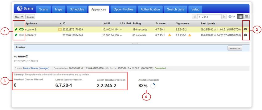
Table of Contents
Preface
Get Started
Before you begin ...................................................................................................................... 8
    Check package accessories .............................................................................................. 8
    Network requirements / configuration .......................................................................... 8
Best Practices for internal scanning .................................................................................... 10
Quick Start ............................................................................................................................. 11
    Step 1 - Connect the Scanner Appliance to the Network ........................................... 11
    Step 2 - Power On the Scanner Appliance.................................................................... 12
    Step 3 - Activate the Scanner Appliance ...................................................................... 14
    We recommend one more thing ................................................................................... 16

Scanner Appliance Tour
A Quick Look at the Appliance.............................................................................................              18
Navigating the Appliance UI ................................................................................................            20
System Reboot and Shutdown .............................................................................................                26
Configure VLANs and Static Routes ....................................................................................                  27
Configure Static IP Address ..................................................................................................          29
Configure IPv6 Address for Scanning ..................................................................................                  33
Proxy Configuration ..............................................................................................................      33
Split Network Configuration ................................................................................................            38
Ethernet Port Configuration .................................................................................................           42
Reset the Network Configuration ........................................................................................                44
Changing the Network Configuration .................................................................................                    45

Troubleshooting
How can I test network connectivity?.................................................................................                   48
Communication Failure message ........................................................................................                  48
Appliance Network Errors ....................................................................................................           49
Network Errors using older appliance model.....................................................................                         52
Where can I find the model number and serial number? ................................................                                   53

Appendix A - Product Specifications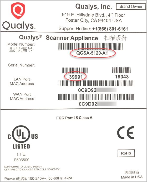
Contents

Appendix B - Software Credits
Appendix C - Safety Notices

                                4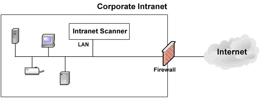
Preface

Preface
This user guide introduces the Qualys Scanner Appliance. The Scanner Appliance offers
Qualys users the ability to extend their use of the service to assess the security of internal
network systems, devices and web applications.
Note: Your use of the Qualys Scanner Appliance is subject to the terms and conditions of
the Qualys Service User Agreement.

About Qualys
Qualys, Inc. (NASDAQ: QLYS) is a pioneer and leading provider of cloud-based security and
compliance solutions. The Qualys Cloud Platform and its integrated apps help businesses
simplify security operations and lower the cost of compliance by delivering critical
security intelligence on demand and automating the full spectrum of auditing,
compliance and protection for IT systems and web applications.
Founded in 1999, Qualys has established strategic partnerships with leading managed
service providers and consulting organizations including Accenture, BT, Cognizant
Technology Solutions, Deutsche Telekom, Fujitsu, HCL, HP Enterprise, IBM, Infosys, NTT,
Optiv, SecureWorks, Tata Communications, Verizon and Wipro. The company is also a
founding member of the Cloud Security Alliance (CSA).
For more information, please visit www.qualys.com.

Contact Qualys Support
Qualys is committed to providing you with the most thorough support. Through online
documentation, telephone help, and direct email support, Qualys ensures that your
questions will be answered in the fastest time possible. We support you 7 days a week,
24 hours a day. Access support information at www.qualys.com/support/.

                                              5
Preface
6Get Started
Get Started
Welcome to the Qualys Scanner Appliance, an option with the Qualys Cloud Platform
from Qualys, Inc. With the Qualys Scanner Appliance, you can assess internal network
devices, systems and web applications. The Scanner Appliance is a robust, scalable
solution for scanning networks of all sizes including large distributed networks.
It’s easy to set up a Scanner Appliance within your network. Let’s get started!
Before you begin
Best Practices for internal scanning
Quick Start
Interested in Virtual Appliances?
Qualys Virtual Scanner Appliance is packaged and qualified for deployment on a
variety of virtualization and cloud platforms. Please contact your TAM or Qualys
Support if you’re interested in adding Virtual Appliances to your license.
Desktop/Laptop: VMware Workstation, Player, Fusion, Oracle VirtualBox
Client/Server: VMware vCenter/vSphere, Citrix XenServer, Microsoft Hyper-V
Cloud: Amazon EC2 - Classic, Amazon EC2 - VPC, Microsoft Azure, Google GCE,
OpenStack
Learn more
Qualys Virtual Appliance: Platform Qualification Matrix
7Get Started
Before you begin
Before you begin
Check package accessories
Your starter kit package should contain these components. If any components are missing
or damaged, please contact Qualys Support.
Qualys Scanner Appliance User Guide
AC power cord
CAT6 cable
Rack screws (quantity 4) - 10-32 x 3/4", Phillips, black matte, with washer
USB-to-RS232 converter cable
Network requirements / configuration
Bandwidth Minimum recommended bandwidth connection of
1.5 megabits per second (Mbps) to the Qualys Cloud
Platform.
Outbound HTTPS Access The local network must be configured to allow outbound
HTTPS (port 443) access to the Internet, so that the
Scanner Appliance can communicate with the Qualys
Cloud Platform.
Appliance Access to Qualys The Scanner Appliance must be able to reach certain
Cloud Platform infrastructure located at the Qualys Cloud Platform where
your Qualys account is located.
Tip - Log into your account and go to Help > About to see
the Qualys Cloud Platform URLs.
Appliance Access to The IP addresses for the hosts to be scanned must be
Target Host IPs accessible to the Scanner Appliance. The Appliance must
be able to resolve external DNS for the hostnames to be
scanned.
LAN Interface is Default The LAN interface services both scanning traffic and
management traffic to the Qualys Cloud Platform, unless
split network configuration is defined for the Appliance.
See Split Network Configuration.
8Get Started
Before you begin
VLAN Support VLAN configuration options: 1) If you have connected the
LAN interface to a 802.1q trunked port and need your
Scanner Appliance to use VLAN tags on the LAN default
network, enter the VLAN tag number using the Appliance
console. 2) For any Appliance, you can choose option 1)
and also configure more VLANs (to be used for scanning)
using the Qualys user interface.
DHCP or Static IP By default the Scanner Appliance is pre-configured with
DHCP. If configured with a static IP address, be sure you
have the IP address, netmask, default gateway, primary
DNS and WINS server (if appropriate).
Proxy Support The Scanner Appliance includes Proxy support with or
without authentication — Basic or NTLM. Proxy-level
termination (as implemented in SSL bridging, for example)
is not supported. SOCKS proxies are not supported.
WINS Support If your network is running Windows Internet Naming
Service (WINS), the Scanner Appliance needs to use it for
host name resolution during scanning. For an Appliance
configured with DHCP, please be sure your WINS server IPs
(primary and secondary) are added to your DHCP subnet
configuration using “option netbios-name-servers WINS1,
WINS2;”. For an Appliance with a static IP address, the
WINS servers are defined with the static IP settings using
the Appliance console.
Network Time Protocol (NTP) The Scanner Appliance syncs the time from the Qualys
SOC (Security Operations Center) for your
account/location automatically. For this reason, there is
nothing you need to configure for NTP.
9Get Started
Best Practices for internal scanning
Best Practices for internal scanning
Here are our best practices related to internal scanning.
Avoid scanning through a firewall from the inside out
Problems can arise when scan traffic is routed through the firewall from the inside out, i.e.
when the scanner Appliance is sitting in the protected network area and scans a target
which is located on the other side of the firewall. We recommend placing scanner
Appliances in your network topology in a way that scanning and mapping through a
firewall from the inside out is avoided if possible.
Learn more
Scanning through a firewall
Check network access to scanners
Go to Help > About in the application. The Scanner Appliances section lists URLs at the
SOC (Security Operations Center) for your account/location. Your Scanner Appliances
must be able to contact these URLs on port 443. For Private Cloud Platform, the URLs
displayed are appropriate to your local on-site SOC.
Learn more
How to check network access to scanners
Consult your network group for scanner placement
It's highly recommended that you work with your network group to determine where to
place Scanner Appliances in an enterprise network environment. Some things to consider:
place Scanner Appliances as close to target machines as possible, and make sure to
monitor and identify any bandwidth restricted segments or weak points in the network
infrastructure. Scanning through layer 3 devices (such as routers, firewalls and load
balancers) could result in degraded performance so you may consider using our VLAN
tagging feature (VLAN trunking) to circumvent layer 3 devices to avoid potential
performance issues.
10Get Started
Quick Start
Quick Start
Once you complete the Quick Start you’re ready to start scanning! It takes just a couple of
minutes. It’s important that you complete the steps in the order shown.
Step 1 - Connect the Scanner Appliance to the Network
Qualys strongly recommends the Scanner Appliance be plugged into a Managed Power
Supply. On the rare occasion where the Scanner Appliance may need to be rebooted,
utilizing the MPS will allow for remote rebooting in unmanned or high security areas.
Set Up Network Connection
The Scanner Appliance connects like any other computer to a switch on your network.
To set up the network connection, follow these steps:
• Connect one end of an Ethernet cable to the Ethernet LAN port on the Scanner
Appliance (back panel).
• Connect the other end of the Ethernet cable to a 10BASE-T or 100BASE-TX or
1 Gigabit switch on your network.
Remote Console Interface Set Up (optional)
The Remote Console interface supports remote configuration and management of the
Scanner Appliance using a VT100 terminal, such as Windows HyperTerminal.
Figure 1-1. Set up for Remote Console Interface
A USB-to-RS232 converter cable allows you to connect to their terminal server via network
cable. Qualys recommends the following USB-to-RS232 converter cable:
IOGEAR USB-Serial Model GUC232A
Full specifications: http://www.iogear.com/product/GUC232A/
Keystroke File Not Supported: The Remote Console interface is not intended for uploading
the whole scanner configuration by means of a pre-defined “keystroke file.” Uploading
such a file will result in lost characters and incorrect configuration.
11Get Started
Quick Start
To set up the Remote Console interface, follow these steps:
1 Be sure the terminal server is up and running. Also check the terminal server
settings. The following settings are required. Note - Stop Bits must be set to 2.
Port Setting Value
Bits per second (Baud rate) 9600
Data Bits 8
Parity None
Stop Bits 2
Flow Control None
Terminal Emulation VT100
2 Connect one end of the USB-to-RS232 converter cable to a USB port on the Scanner
Appliance (back panel).
3 Connect the other end of the USB-to-RS232 converter cable to your terminal server
via network cable.
4 Connect the Scanner Appliance (see Step 2 - Power On the Scanner Appliance)
Note: In the case where the Scanner Appliance is already powered on, you must
reboot the Scanner Appliance before taking the next step and making any
configurations. To reboot, press the Down arrow on the LCD interface until the
SYSTEM REBOOT message appears and then press ENTER. Please make sure that
the Scanner Appliance has fully rebooted (this takes up to 3 minutes).
5 Press the ENTER key on the VT100 terminal’s keyboard to display the Remote
Console interface. You will notice the MAC address for the Scanner Appliance
appears.
Step 2 - Power On the Scanner Appliance
To power on the Scanner Appliance, follow these steps:
1 Connect the AC power cord into the Power Supply Socket.
Note: Qualys strongly recommends the Scanner Appliance be plugged into a
Managed Power Supply. On the rare occasion where the Scanner Appliance may
need to be rebooted, utilizing the MPS will allow for remote rebooting in
unmanned or high security areas.
2 Press the power button on the back panel. Be sure that the power button has a
green backlight.
12Get Started
Quick Start
3 Welcome to Qualys appears in the Scanner Appliance interface followed by other
informational messages during the boot process which takes approximately two
minutes. These messages appear in the order shown:
Welcome to Qualys
Qualys Scanner is starting up...
Filesystem check in progress...
Qualys Scanner is coming up...
4 Once the Scanner Appliance makes a successful connection to the Qualys Cloud
Platform you’ll see the activation code message.
ACTIVATION CODE — The activation code for the Scanner Appliance is displayed.
A unique code is assigned to each Appliance. Make a note of the activation code
and then go to enter the activation code.
You might see an appliance configuration error instead. This will be reported if the
Scanner Appliance did not make a successful connection to the Qualys Cloud
Platform using its current network settings. The error must be resolved before you
go to Step 3. Need help? See Troubleshooting.
Tip - If you’ve set up the Remote Console, it may be necessary to press the ENTER
key on the VT100 terminal’s keyboard to display the Remote Console interface.
Complete the Network Configuration
Enable the network configurations for the Scanner Appliance, as appropriate, in the order
listed. One or more configurations may be required. Any error must be resolved before
going to Step 3. Refer to Troubleshooting for help with resolving any errors.
Configuration Options For information ...
A Static IP Address See “Configure Static IP Address” on page 29
B Proxy Support See “Proxy Configuration” on page 33
C Split Network See “Enable DHCP on the WAN Interface” on page 39
Configuration and ”Enable DHCP on the WAN Interface” on page 39
using DHCP
D Split Network See “Enable DHCP on the WAN Interface” on page 39
Configuration and ”Enable Static IP on the WAN Interface” on page 39
using a Static IP Address
13Get Started
Quick Start
Use the options chart below to determine the configurations needed.
DHCP Static IP DHCP Static IP
w/o Proxy w/o Proxy with Proxy with Proxy
Standard Config no action A B A&B
Split Netw. Config: C A&C B&C A, B, & C
DHCP on WAN
Split Netw. Config: D A&D B&D A, B, & D
Static IP on WAN
The Scanner Appliance supports VLAN interface configuration (802.1Q). For information,
see Configure VLANs and Static Routes.
You may see an appliance configuration error one or two more times, depending on how
many configurations are needed. For example, if the Scanner Appliance is installed on a
network with DHCP and a Proxy server, and you want split network configuration with
DHCP, you enable options B and C. After you enable option B, you’ll see another error
prompting you to make another configuration.
Step 3 - Activate the Scanner Appliance
You will need a Qualys user account with the role of Manager or Unit Manger. Check to be
sure that you have your account information.
1 Open a browser and go to the platform URL where your account is located. Please
refer to your registration email containing your platform URL and login
credentials. A Manager or Unit Manager account is required.
2 On the Qualys LOGIN page, enter your user name (login) and password, and then
click LOGIN. You are prompted to review and accept the licensing agreement when
you log into your account for the first time. Your Qualys Home page appears upon
successful login.
3 Select VM from the application picker.
4 Go to Scans > Appliances.
5 Select New > Scanner Appliance and enter the activation code for the appliance
(as it appears in the ACTIVATION CODE screen in your Appliance’s user interface.
Note: The activation code is shown only when the Appliance has not been
activated yet.
6 (Unit Manager only) From the Add To menu, select an asset group that you want
to add the Scanner Appliance to. This will make the Appliance available to users
in your business unit.
14Get Started
Quick Start
7 Click Activate. Then the Scanner Appliance attempts to log in to the Qualys Cloud
Platform.
Note: It may take a few minutes for the Scanner Appliance activation to occur. If
you prefer not to wait, complete the activation manually by restarting the Scanner
Appliance. Just press the Down arrow until the SYSTEM REBOOT screen appears
and then press ENTER. When REALLY REBOOT SYSTEM? appears press ENTER.
8 The SCANNER APPLIANCE NAME–IP ADDRESS message appears after the Scanner
Appliance makes a successful login to the Qualys Cloud Platform. Do you see
another message instead? See Troubleshooting and we’ll help you with this.
That’s all there is to it!
You are ready to start scanning with your Qualys Scanner Appliance! You’ll see the
Scanner Appliance name and IP address in the interface (LCD or Remote Console), this
indicates you have completed the Quick Start, the Scanner Appliance has been added to
your subscription.
Tip - Before you launch scans using the Scanner Appliance, we recommend you log into
the Qualys user interface and check the Appliance status on the appliances list.
Scanner Appliance Name and IP Address
The Scanner Appliance name and IP address appear as shown below.
The Scanner Appliance name displayed is “is_username”, where username is your
Qualys user name. The name can be changed using the Qualys user interface.
The IP address is available for information purposes only. The Scanner Appliance
is remote controlled by the Qualys Cloud Platform, and the Appliance does not
allow incoming logins or connections from the network. If split network
configuration is enabled, the IP address for the LAN interface is displayed.
The Qualys Cloud Platform indicator for your account appears in the lower right
corner.
15Get Started
Quick Start
Proper Shutdown
Just go to the LCD display on the front panel. Press the down arrow until SYSTEM
SHUTDOWN appears, and then press ENTER. When you see REALLY SHUTDOWN SYSTEM?
press ENTER. You'll notice the Scanner Appliance lights and LEDs are turned off. Then you
can safely disconnect the power supply.
Don't want to use the LCD interface? No problem, you can press the power button on the
back panel instead.
We recommend one more thing
Check your Scanner Appliance status in Qualys portal. Go to Scans > Appliances and
select your Appliance. You’ll see details in the preview pane.
1) tells you your Scanner Appliance is ready. Now you can start internal scans! Next to
the status you’ll see the busy icon is greyed out until you launch a scan, then it looks like
this .
You might also check out:
2) tells you that your Scanner Appliance is a Physical Appliance and means it’s a
Virtual Appliance.
3) Latest software versions - these are installed automatically as part of the activation.
4) The available capacity will be 100% until you launch a scan. You can come back and
check on this at any time.
16Scanner Appliance Tour
Scanner Appliance Tour
This section gives you a tour of the Qualys Scanner Appliance, its features, basic operation
and configuration options.
A Quick Look at the Appliance
Navigating the Appliance UI
System Reboot and Shutdown
Configure VLANs and Static Routes
Configure Static IP Address
Configure IPv6 Address for Scanning
Proxy Configuration
Split Network Configuration
Reset the Network Configuration
Changing the Network Configuration
17Scanner Appliance Tour
A Quick Look at the Appliance
A Quick Look at the Appliance
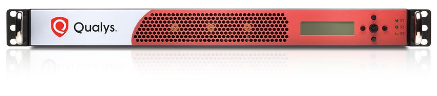
Front Panel
You’ll see Welcome to Qualys in the LCD display when you connect the Appliance to the
network for the first time. After you’ve successfully completed the Quick Start steps for
your Scanner Appliance, you’ll see the Scanner Appliance name and IP address.
Use the keypad to enter information and respond to prompts.
• Left and Right arrow buttons move the cursor to left/right in an entry field.
• Up and Down arrow buttons scroll through menu options, and scroll through
characters in an entry field.
• ENTER button, in the center, is used to confirm entries and move to the next
screen.
Tell me about the LEDs.
• S1 tells you a Qualys scan is in progress on the Scanner Appliance.
• S2 tells you a software update to the Scanner Appliance is in progress.
• S3 is not used.
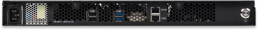
Back Panel
The Appliance’s back panel includes: the power socket, the Ethernet LAN port, the
Ethernet WAN port, two USB 2.0 ports and two USB 3.0 ports.
18Scanner Appliance Tour
A Quick Look at the Appliance
Power socket - Use to connect the power connector to the Appliance.
Power button - Use to power on the Appliance. A green light indicates the Appliance is
turned on.
LAN/WAN ports - Use to connect the Appliance to a hub or switch on your network using
a straight through CAT6 twisted pair Ethernet cable. The LAN port is required. The WAN
port is only required if you choose the split network configuration option.
USB ports - Connect a USB-to-RS232 converter cable to a USB port if you want to use the
optional Remote Console interface (any port may be used).
Appliance UI
The Scanner Appliance has a user interface for configuration and management. You can
choose to use the LCD display and keypad on the front panel, or the optional Remote
Console interface. Both the LCD display and Remote Console offer the same functionality
and share the same menus and navigation (ENTER key and arrows) for a consistent user
experience.
The Remote Console interface supports remote configuration and management of the
Scanner Appliance using a VT100 terminal, such as Windows HyperTerminal. See Remote
Console Interface Set Up (optional).
19Scanner Appliance Tour
Navigating the Appliance UI
Navigating the Appliance UI
Main Menu
To access the Scanner Appliance main menu, press ENTER when the Scanner Appliance
name and IP address are displayed. The first menu option displayed is SETUP NETWORK.
Figure 2-1. Scanner Appliance Main Menu
To move up through the menu options, press the Up arrow. To move down through the
menu options, press the Down arrow. To select an option, press ENTER. To exit the main
menu, press the down arrow button until the EXIT THIS MENU option appears, and then
press ENTER.
20Scanner Appliance Tour
Navigating the Appliance UI
Navigation Indicators
Each Scanner Appliance screen displays one or more indicators in the top right corner,
indicating the navigation options available from the current screen.
LCD Remote Description
Button Console
Key
ENTER Confirm a selection. After you press ENTER, another
screen appears.
RIGHT Move the cursor to the right in an entry field.
LEFT Move the cursor to the left in an entry field.
UP Used to:
— Increase the value in an entry field
— Move up through menu options
— Cancel a confirmation message
DOWN Used to:
— Decrease the value in an entry field
— Move down through menu options
Note these important guidelines for using buttons: 1) Press one button at a time, 2) Do not
hold down an arrow button (except as noted in guideline 3), instead press the arrow
multiple times, and 3) When entering a user name or password, you can hold down the Up
and Down arrow buttons to scroll through characters quickly.
Entering Information
The Scanner Appliance user interface (LCD and Remote Console) allow users to enter
information in the fields provided using arrow keys. The Left and Right arrows move the
cursor to the left and right and the Up and Down arrows are used to scroll through
characters. Some fields allow certain characters to be entered. The character restrictions
are described below.
Up and Down Arrows
Using the LCD user interface use the Up and Down arrows to enter characters in a field.
Using the Remote Console interface you have the option to use the Up and Down arrows
or to use your keyboard to enter characters.
In numeric entry fields, you press the Up and Down arrows to select a value between
0 and 9. When a numeric entry field is first displayed, a default value appears.
21Scanner Appliance Tour
Navigating the Appliance UI
In text entry fields where you enter a user name and password, you press the Up and
Down arrows to select a character (numeric, alphabetic, space, underscore or special
character). In these fields, you can hold the Up arrow or the Down arrow to scroll through
the available characters. When a text entry field is first displayed, the text entry field is
blank (filled with spaces).
Scrolling through Characters
Some fields allow you to select characters. Press the Up arrow to scroll through characters
in ascending order. Starting from the space character, the characters appear in this order:
lowercase letters (a to z), space, numbers (0 to 9), underscore, special characters (for Proxy
user name and password only), uppercase letters (A to Z).
Figure 2-2. Scrolling characters in ascending order
Press the Down arrow to scroll through characters in descending order. Starting from the
space character, the characters appear in this order: uppercase letters (Z to A), special
characters (for Proxy user name and password only), underscore, numbers (9 to 0), space,
lowercase letters (z to a).
22Scanner Appliance Tour
Navigating the Appliance UI
Figure 2-3. Scrolling characters in descending order
Space Character
When a text field entry contains fewer characters than the character positions on the
interface screen, you must select the space character for the unused positions, before or
after the field entry. Only the characters associated with the field entry and space
characters may be included in a text field entry.
Embedded spaces are not permitted in text field entries.
The space character may be used to remove characters when editing text fields, except the
Proxy password. To remove a character in an entry field using the LCD user interface,
move the cursor on the character (using the Left and Right arrows), select the space
character (using the Up and Down arrows) and then press ENTER. Any space characters
entered appear in the interface screen until the next time you revisit the screen.
IP Addresses
Entry fields for IP addresses are pre-filled with values in this format: nnn.nnn.nnn.nnn
The IP address format displays values for each character position in all octets. When
entering an IP address, you replace the three “n” digits for each octet as appropriate. If an
octet has less than three digits, then the octet must include leading zeros. For example, to
specify the IP address “194.55.176.2”, you input the IP address as “194.055.176.002”.
23Scanner Appliance Tour
Navigating the Appliance UI
Windows Domain Name
The WINS DOMAIN field in the static IP address configuration allows you to enter the
domain name (for example, mydomain.com). The domain name entry can have a
maximum length of 32 characters. These characters are allowed: uppercase letters,
numbers, underscore(_), and period (.).
Figure 2-4. Special characters in the Windows domain field
The screen displays 16 characters of the WINS DOMAIN field entry and it scrolls left. For
example, the first character of the domain name is hidden when the 17th character is
entered. As each additional character is entered, the domain name scrolls left.
Tips - The space character may be used to remove characters when editing the domain
name entry. There’s a shortcut for clearing a domain name entry. Just press the Left arrow
and Right arrow at the same time.
Proxy User Name
For the Proxy user name in the PROXY USER field you may enter a maximum of 32
characters including lower case letters, upper case letters, numbers, and underscore.
These special characters can be used: underscore (_), dash (-), backslash (\), period (.), at
sign (@).
Figure 2-5. Special characters in the Proxy user field
The screen displays 16 characters of the PROXY USER field entry, and it scrolls left. For
example, the first character of the Proxy user name is hidden when the 17th character is
entered. As each additional character is entered, the Proxy user name scrolls left. The
space character may be used to remove characters.
The format of a Proxy user entry is: “domain\user”. If there is a backslash in the middle of
the entry, the Appliance interprets the string before the backslash as the domain name.
No double backslashes (\\) are needed in front of the “domain\user” format.
24Scanner Appliance Tour
Navigating the Appliance UI
Proxy Password
The PROXY PASSW allows you to enter a maximum of 16 characters including lower case
letters, upper case letters, numbers, and underscore. Many special characters are allowed.
These characters are shown in ascending order in the table below. Using the LCD
interface, to scroll through characters 1 to 30, press the Up arrow. To scroll through
characters in descending order, press the Down arrow.
Special Characters in the PROXY PASSW field
Order Character Name Order Character Name
(ascending) (ascending)
1 _ underscore 16 + plus
2 - hyphen 17 = equal
3 \ backslash 18 ( parenthesis
left
4 / slash 19 ) parenthesis
right
5 | bar 20 { brace left
6 ~ tilda 21 } brace right
7 ! exclamation 22 [ bracket left
8 ? question 23 ] bracket
right
9 @ at sign 24 < less
10 # number sign 25 > greater
11 $ dollar 26 ; semicolon
12 % percent 27 “ double
quote
13 ^ asciicircum 28 ` grave
14 & ampersand 29 , comma
15 * asterisk 30 . period
25Scanner Appliance Tour
System Reboot and Shutdown
System Reboot and Shutdown
It is important to follow the proper system shutdown instructions described below. If you
do not follow these instructions, file system corruption may occur.
How to reboot the system
1 With the Scanner Appliance name and IP address displayed, press ENTER.
2 When the SETUP NETWORK menu option appears, press the Down arrow to
navigate through the menu options.
3 When the SYSTEM REBOOT menu option appears, press ENTER to select the option.
4 When the REALLY REBOOT SYSTEM? prompt appears, press ENTER to confirm.
Review the confirmation messages starting with REBOOTING SYSTEM message. The
SCANNER APPLIANCE NAME–IP ADDRESS is displayed after the Scanner Appliance makes
a successful connection to the Qualys Cloud Platform. This message indicates the Scanner
Appliance is ready for scanning. If another message appears you need to activate the
Scanner Appliance or troubleshoot the issue before scanning. See Troubleshooting for
help with resolving any errors.
How to shutdown the system
You can power off the system using the shutdown button or using the Appliance UI.
Using the Appliance UI:
1 With the Scanner Appliance name and IP address displayed, press ENTER.
2 When the SETUP NETWORK menu option appears, press the Down arrow to
navigate through the menu options.
3 When the SYSTEM SHUTDOWN menu option appears, press ENTER.
4 When the REALLY SHUTDOWN SYSTEM? prompt appears, press ENTER to confirm.
5 Important! The Scanner Appliance should now power down within 60 seconds.
When this message appears: “It’s now safe to unplug the box”, then you can safely
unplug the Scanner Appliance.
26Scanner Appliance Tour
Configure VLANs and Static Routes
What happens after restart?
When you restart the Scanner Appliance, several messages appear during the startup
process, as described below:
1 When the system is restarted, informational messages appear in the screen during
the boot process. These messages appear in the order shown below:
Welcome to Qualys
Qualys Scanner is starting up...
Filesystem check in progress...
Qualys Scanner is coming up...
2 The Appliance attempts to connect to the Qualys Cloud Platform using its
configuration. During this phase, these messages appear in the order shown
below:
CONTACTING QUALYS
Filesystem check in progress...
CONTACTING QUALYS
3 The SCANNER APPLIANCE NAME–IP ADDRESS is displayed after the Scanner
Appliance makes a successful connection to the Qualys Cloud Platform. This
means your the Scanner Appliance is ready to start scanning. If another message
appears you need to take some action before you can start scanning:
• ACTIVATION CODE — The Scanner Appliance needs to be activated. Refer to
the Quick Start for instructions.
• Appliance configuratin error — An error prevented the Scanner Appliance
from making a connection to the Qualys Cloud Platform. This issue must be
resolved before scanning. See Troubleshooting for help with resolving the
issue.
Configure VLANs and Static Routes
The Scanner Appliance supports VLAN trunking on the LAN interface for scanning traffic.
VLAN trunking on the WAN interface is not supported. One VLAN interface (802.1Q) may
be configured using the Scanner Appliance user interface (LCD and Remote Console). Up
to 4094 VLANs and static routes can be defined using the Qualys web application.
How it works - The Scanner Appliance adds VLAN tag(s) to all scanning packets following
the 802.1Q tagging protocol.
27Scanner Appliance Tour
Configure VLANs and Static Routes
Configure VLAN using the Appliance UI
A VLAN that is defined using the Scanner Appliance UI is saved on the Appliance and
can’t be edited using the Qualys UI.
Important! After making configuration changes, be sure to complete the entire network
configuration so that your Scanner Appliance makes a successful connection to the
Qualys Cloud Platform.
Configure VLAN
To configure the Scanner Appliance with a default VLAN interface on the LAN interface,
follow these steps:
1 Go to the SETUP NETWORK menu option and press ENTER to continue.
2 Press the Down arrow one time. When the ENABLE VLAN ON LAN menu option
appears, press ENTER to continue.
3 When the prompt VLAN 0-4094 appears, specify the VLAN ID. The value “0000”
appears in the screen by default. Specify the VLAN ID, and then press ENTER to
continue.
Change VLAN
A default VLAN that you’ve added using the Scanner Appliance user interface (LCD and
Remote Console) can be changed at any time. To do this, select the CHANGE VLAN ON LAN
menu option from the SETUP NETWORK menu. Then enter another VLAN ID and press
ENTER.
Disable VLAN
To disable a default VLAN, select the CHANGE VLAN ON LAN menu option from the SETUP
NETWORK menu. Then enter the VLAN ID “0000” and press ENTER. After the configuration
is disabled the ENABLE DHCP ON LAN menu option appears on the Scanner Appliance
interface.
Configure VLANs / Static Routes using the Qualys UI
Configuring VLANs and static routes is supported using the Qualys UI. Just go to the
appliances list (Scans > Appliances) and edit the Appliance settings. The VLANs and static
routes you add are saved with your account information on the Qualys Cloud Platform.
You can add up to 4094 VLANs to devices with a serial number over 29000 and up to
99 VLANs to devices with a serial number under 29000. Add up to 99 static routes.
Don’t see these settings? The VLAN trunking feature must be turned on for your account.
Please contact Support or your Technical Account Representative if you’d like us to turn it
on for you.
28Scanner Appliance Tour
Configure Static IP Address
Configure Static IP Address
If DHCP is not on your network, you must enable the Scanner Appliance with a static
IP address using the ENABLE STATIC IP ON LAN menu option. One of these
configurations is required.
Entry fields for IP addresses used in the static IP address configuration are pre-filled with
three digits for all octets, and you must enter a value for each digit. For example, to specify
the IP address “176.34.20.5”, you input the IP address as “176.034.020.005”. See IP
Addresses for details.
Tell me the steps
When enabling a static IP address on the LAN interface, you must enter network
configuration settings for the Scanner Appliance so that the Appliance can communicate
with the Qualys Cloud Platform. Also, you have the option to enter some network settings
for informational purposes.
To enable a static IP address on the LAN interface for the Scanner Appliance, follow
these steps:
1 Go to the SETUP NETWORK menu option and press ENTER to continue.
2 Press the Down arrow until the ENABLE STATIC IP ON LAN menu option appears.
Then press ENTER to continue.
3 When the CFG LAN STATIC NETWORK PARAMS? prompt appears, press ENTER to
continue. Or press the Up arrow to quit this procedure and return to the
SETUP NETWORK menu option.
Entering parameters
The Scanner Appliance user interface (LCD and Remote Console) allows users to enter
information in the fields provided using the arrow keys. Use the Left and Right arrows to
move the cursor to the left and right, and use the Up and Down arrows to scroll through
characters. With the Remote Console interface, you have the option to enter characters
using the VT100 terminal’s keyboard.
1 When the LAN IP ADDR prompt appears, enter the static IP address, and then
press ENTER to continue.
2 When the LAN NETMASK prompt appears, use the Up and Down arrows to scroll to
the desired netmask value. For information about netmask values, see Tell me
about LAN Netmask. After selecting a netmask value, press ENTER to continue.
3 When the LAN GATEWAY prompt appears, enter the gateway IP address, and then
press ENTER to continue.
29Scanner Appliance Tour
Configure Static IP Address
4 When the LAN DNS1 prompt appears, enter the IP address for the primary DNS
server, and then press ENTER to continue.
5 When the LAN DNS2 prompt appears, enter the IP address for the secondary DNS
server. This entry is optional. Press ENTER to continue.
6 Next are three optional network settings, used for informational purposes only.
These Appliance settings are not used to access the internal network for scanning
or the Qualys Cloud Platform for software updates. To skip these settings, press
ENTER three times.
– When the LAN WINS1 prompt appears, enter the IP address for the primary
WINS server, if any. Press ENTER to continue.
– When the LAN WINS2 prompt appears, enter the IP address for the secondary
WINS server, if any. Press ENTER to continue.
– When the DOMAIN NAME prompt appears, enter the domain name for the
DNS server (for example, mydomain.com). Press ENTER to continue.
7 When the REALLY SET LAN STATIC NETWORK? prompt appears, press ENTER to
continue. Or press the Up arrow to quit this procedure and return to the
SETUP NETWORK menu option.
8 Review the confirmation messages. The Scanner Appliance attempts to make a
connection to the Qualys Cloud Platform using the new configuration. Upon
success the SCANNER APPLIANCE NAME–IP ADDRESS message appears and the
static IP address is enabled.
Confirm the configuration
When you see SCANNER APPLIANCE NAME–IP ADDRESS this means you are ready to start
scanning. This message appears if the Scanner Appliance made a successful connection to
the Qualys Cloud Platform using the new configuration.
An appliance configuration error appears if the Scanner Appliance failed to make a
connection to the Qualys Cloud Platform. A error may occur because the static IP
parameters you entered are incorrect, or they do not match the static IP configuration on
your network. See Troubleshooting for help with resolving the issue.
30Scanner Appliance Tour
Configure Static IP Address
Tell me about LAN Netmask
When entering static network parameters, you will notice that the cursor does not appear
after the LAN NETMASK prompt and you cannot enter characters in the entry field. At first,
the netmask “255.255.255.000” appears. Use the Up and Down arrows to scroll through
valid netmasks. When the appropriate netmask value appears, press ENTER to confirm.
Possible netmask values are listed below. If you press the Down arrow, the values appear
in this order: “255.255.255.000”, “255.255.254.000”, “255.255.252.000... If you press the
Up arrow, the values appear in this order: “255.255.255.000”, “255.255.255.128”,
“255.255.255.192”...
Scrolling netmask values in the Netmask field
Prefix Netmask value Prefix Netmask value
/24 255.255.255.000 /9 255.128.000.000
/23 255.255.254.000 /8 255.000.000.000
/22 255.255.252.000 /7 254.000.000.000
/21 255.255.248.000 /6 252.000.000.000
/20 255.255.240.000 /5 248.000.000.000
/19 255.255.224.000 /4 255.000.000.000
/18 255.255.192.000 /3 224.000.000.000
/17 255.255.128.000 /2 192.000.000.000
/16 255.255.000.000 /1 128.000.000.000
/15 255.254.000.000 /30 255.255.255.252
/14 255.252.000.000 /29 255.255.255.248
/13 255.248.000.000 /28 255.255.255.240
/12 255.240.000.000 /27 255.255.255.224
/11 255.224.000.000 /26 255.255.255.192
/10 255.192.000.000 /25 255.255.255.128
31Scanner Appliance Tour
Configure Static IP Address
Interface - Enable Static IP on LAN
(*) One option may be enabled: ENABLE VLAN ON LAN or ENABLE DHCP ON LAN. After one
option is enabled, the other option disappears from the SETUP NETWORK menu.
Figure 2-6. User Interface for Enable Static IP on LAN
We’ll update menu options once you configure settings. Once you configure ENABLE
STATIC IP ON LAN the option will change to CHANGE STATIC IP ON LAN. Once you
configure ENABLE DHCP ON LAN the option will appear as RENEW DHCP ON LAN.
32Scanner Appliance Tour
Configure IPv6 Address for Scanning
Configure IPv6 Address for Scanning
You have the option to configure the Scanner Appliance with an IPv6 address on the LAN
interface - this will be used for scanning IPv6 hosts.
How it works - Once configured scanning traffic is routed through the LAN interface - LAN
IPv4 for scanning IPv4 hosts, and LAN IPv6 for scanning IPv6 hosts. All management traffic
(software updates, health checks, etc) is routed through the LAN IPv4 interface.
A few things to consider
• First go to the Appliance UI and complete the Quick Start. You must configure an
IPv4 address on the LAN interface (using DHCP or a static IP).
• Be sure your Scanner Appliance has successfully connected to the Qualys Cloud
Platform.
• The IPv6 Scanning feature must be enabled for your subscription.
Tell me the steps
1 Log in to the Qualys UI.
2 Go to Scans > Appliances and edit your Scanner Appliance. You’ll see the
Appliance wizard.
3 Under LAN settings select “Enable IPv6 for this scanner”. You can choose
“Automatically” and we’ll do IP assignment through router advertisement, or
choose “Static” and assign a static IP address.
Don’t see these settings? This means IPv6 Scanning is not turned on for your
account. Please contact Support or your Technical Account Manager if you’d like
us to turn it on for you.
4 Be sure to save the Appliance settings.
Proxy Configuration
If the Scanner Appliance is behind a Proxy server, you need to enable a Proxy
configuration using the ENABLE PROXY menu option. Authentication (Basic or NTLM) of
the Scanner Appliance connection to your Proxy server can be enabled by configuring the
Proxy user and password fields.
The Scanner Appliance uses Secure Sockets Layer (SSL) protocol (HTTPS) to secure its
connection to the Qualys web application, in a similar way that a web browser does to a
secure web server. If the Qualys connection must pass through a Proxy server, then you
must enable the Proxy option on the Scanner Appliance. This configuration re-directs
Qualys outbound connections through the Proxy server.
33Scanner Appliance Tour
Proxy Configuration
Your Proxy server must be configured to tunnel or pass through the SSL session to the
Qualys web application. This ensures a secured end-to-end connection. SSL bridging or
tunnel termination must not be configured in your Proxy server when supporting the
Scanner Appliance.
Tell me the steps
To configure the Scanner Appliance with Proxy support, follow these steps:
1 Go to the SETUP NETWORK menu option.
2 Press the Down arrow until the ENABLE PROXY menu option appears. Then press
ENTER to continue.
3 When the CONFIG PROXY PARAMETERS prompt appears, press ENTER to continue.
Or press the Up arrow two times to quit this procedure and return to the SETUP
NETWORK menu option.
Entering parameters
Enter Proxy parameters using the Up and Down arrows to scroll through characters.
1 When the PROXY HOST prompt appears, enter the Proxy server’s FQDN/IP address.
The gateway IP address appears in the screen by default. Use the Scanner
Appliance interface to enter an FQDN/IP address, and then press ENTER to
continue.
IP addresses are allowed in dotted decimal format, e.g. 176.34.20.5
Supported characters for FQDN: Upper case letters, numbers, dot (.) and hyphen (-)
2 When the PROXY PORT: prompt appears, enter the port number assigned to the
Proxy server. Port “0443” appears in the screen by default. Confirm that the port
number shown is correct or enter a different one, if necessary. When the correct
port number appears, press ENTER to continue.
Supported Characters: numbers only
3 When the PROXY USER: prompt appears, enter the user name for Proxy
authentication. If authentication is not enabled at the Proxy level, leave the entry
field blank. Press ENTER to continue.
Supported Characters: Lower case letters, upper case letters, numbers, and these
special characters: _-\@. (including dot).
4 When the PROXY PASSW prompt appears, enter the password for Proxy
authentication. If authentication is not enabled at the Proxy level, leave the entry
field blank. Press ENTER to continue.
Supported Characters: Lower case letters, upper case letters, numbers, and these
special characters: _-\/|~!?@#$%^&*+=(){}[]:;"`,. (including dot).
34Scanner Appliance Tour
Proxy Configuration
5 When the REALLY ENABLE PROXY? prompt appears, press ENTER to continue. Or
press the Up arrow two times to quit this procedure and return to the
SETUP NETWORK menu option.
6 Review the confirmation messages. The ENABLING PROXY SUPPORT message
appears followed by other messages while the Scanner Appliance attempts to
make a connection to the Qualys Cloud Platform using the new configuration.
Upon success the SCANNER APPLIANCE NAME–IP ADDRESS message appears and the
configured proxy is now confirmed working and being used.
Interface - Enable Proxy
The Scanner Appliance user interface to enable Proxy support is shown below.
Figure 2-7. User Interface for Enable Proxy
35Scanner Appliance Tour
Proxy Configuration
Want to update proxy setting?
Once a Proxy configuration is enabled, the Proxy settings are stored on the Scanner
Appliance. You can change or disable these settings at any time.
To change Proxy parameters, follow these steps:
1 Go to the SETUP NETWORK menu option.
2 Press the Down arrow until the CHANGE PROXY PARAMS menu option appears.
Then press ENTER to continue.
3 Follow the prompts and messages in the Scanner Appliance interface to change
the existing Proxy parameters. Existing parameters are displayed in each screen.
Change and confirm each parameter. If a parameter has not changed, press
ENTER to view the next parameter.
4 When the REALLY ENABLE PROXY? prompt appears, press ENTER to continue. Or
press the Up arrow two times to quit this procedure and return to the
SETUP NETWORK menu option.
5 Review the confirmation messages. The ENABLING PROXY SUPPORT message
appears followed by others.
To disable Proxy parameters, follow these steps:
1 Go to the SETUP NETWORK menu option.
2 Press the Down arrow until the DISABLE PROXY menu option appears. Then press
ENTER to continue.
3 When the REALLY DISABLE PROXY? prompt appears, press ENTER to continue.
Or press the Up arrow two times to quit this procedure and return to the
SETUP NETWORK menu option.
4 Review the confirmation messages.
36Scanner Appliance Tour
Proxy Configuration
Interface - Change Proxy Parameters
Figure 2-8. User Interface for Change Proxy Parameters
Confirm the configuration
When you see SCANNER APPLIANCE NAME–IP ADDRESS this means you are ready to start
scanning. This message appears if the Scanner Appliance made a successful connection to
the Qualys Cloud Platform using the new configuration.
The USER LOGIN prompt appears if the Scanner Appliance made a successful connection
to the Qualys Cloud Platform, however the Appliance has not been activated. See Step 3 in
the Quick Start and follow the instructions to activate the Scanner Appliance.
An appliance configuration error appears if the Scanner Appliance failed to make a
connection to the Qualys Cloud Platform. An error may occur because the Proxy
parameters you entered are incorrect, or they do not match the Proxy configuration on
your network. See Troubleshooting for help with resolving this issue
37Scanner Appliance Tour
Split Network Configuration
Split Network Configuration
The Qualys Scanner Appliance provides two network traffic configurations: Standard and
Split. The Standard configuration is enabled by default. You may enable the Split network
configuration using menu options on the SETUP NETWORK menu.
In the Standard network configuration, the LAN RJ45 Ethernet connector services both
scanning traffic and management traffic to the Qualys Cloud Platform over the Internet.
Figure 2-9. Standard network traffic configuration (default)
In the Split network configuration all Scanner Appliance management traffic, which
includes scan/map job pickup, scan/map data upload, software updates and health
checks are routed through the WAN port, whereas scan traffic uses the LAN port. This
configuration enables the use of Scanner Appliances in networks that do not have direct
Internet access.
Figure 2-10. Split network traffic configuration
No internal traffic is routed or bridged to the WAN port and no management traffic is
routed or bridged to the LAN port.
The Scanner Appliance implements logical separation of scanning traffic and
management traffic regardless of whether you configure the Standard or Split option.
38Scanner Appliance Tour
Split Network Configuration
A few things to consider
Please review these tips and best practices before you configure split network
configuration.
• Check to be sure that network connection to both the LAN and WAN ports on the
Scanner Appliance have been set up properly.
• The Scanner Appliance must be configured with DHCP or a static IP address on the
LAN interface first.
• Using the LAN interface now? If your Scanner Appliance is powered on and
connected to the LAN port only, power down the Scanner Appliance before you
connect the second Ethernet cable to the WAN port.
• Do not configure the LAN and WAN interfaces on the same subnet. This type of
configuration is not supported.
Enable DHCP on the WAN Interface
To configure the WAN interface with DHCP, follow these steps:
1 Select SETUP NETWORK, press the Down arrow until the ENABLE WAN INTERFACE
menu option appears. Then press ENTER to continue.
2 Go to the ENABLE DHCP ON WAN menu option and press ENTER to continue.
3 When the REALLY ENABLE DHCP ON WAN? prompt appears, press ENTER to
continue. Or press the Up arrow two times to quit this procedure and return to the
SETUP NETWORK menu option.
4 Review the confirmation message. When the SCANNER APPLIANCE NAME–IP
ADDRESS appears you are ready to start scanning. If another message appears you
need to complete the Quick Start or resolve the error indicated.
Enable Static IP on the WAN Interface
To configure the WAN interface with a static IP address, follow these steps:
1 Select SETUP NETWORK, press the Down arrow until the ENABLE WAN INTERFACE
menu option appears. Then press ENTER to continue.
2 Go to the ENABLE STATIC IP ON WAN menu option and press ENTER to continue.
3 When the CFG WAN STATIC NETWORK PARAMS? prompt appears, press ENTER to
continue. Or press the Up arrow to quit this procedure and return to the
SETUP NETWORK menu option.
4 When the WAN IP ADDR prompt appears, enter the static IP address, and then
press ENTER to continue.
39Scanner Appliance Tour
Split Network Configuration
5 When the WAN NETMASK prompt appears, use the Up and Down arrows to scroll to
the desired netmask value. After selecting a netmask value, press ENTER to
continue.
6 When the WAN GATEWAY prompt appears, enter the gateway IP address. Then press
ENTER to continue.
7 When the WAN DNS1 prompt appears, enter the IP address for the primary DNS.
Then press ENTER to continue.
8 When the WAN DNS2 prompt appears, enter the IP address for the secondary DNS.
This entry is optional. Press ENTER to continue.
9 When the REALLY SET WAN STATIC NETWORK? prompt appears, press ENTER to
continue. Or press the Up arrow to quit this procedure and return to the
SETUP NETWORK menu option.
10 Review the confirmation message. When the SCANNER APPLIANCE NAME–IP
ADDRESS message appears, you are ready to start scanning. If another message
appears you need to complete the Quick Start or resolve the error indicated.
40Scanner Appliance Tour
Split Network Configuration
Interface - Enable Static IP on WAN
Figure 2-11. Enable Static IP Address on WAN Interface
We’ll update menu options once you configure settings. Once you configure ENABLE
STATIC IP ON WAN the option will change to CHANGE STATIC IP ON WAN. Once you
configure ENABLE DHCP ON WAN the option will appear as RENEW DHCP ON WAN.
41Scanner Appliance Tour
Ethernet Port Configuration
Ethernet Port Configuration
The Scanner Appliance uses Ethernet auto negotiation on scanning and management
ports. Most network devices have auto negotiation enabled. Locked-down port policies
with auto negotiation disabled, such as forcing speed, duplex, and link capabilities, are
outdated. This is due to the maturity of the auto negotiation technology as well as the rate
of adoption by product vendors and consumers over many years.
In the rare and unusual case where auto negotiation is disabled, Ethernet port
configuration on the Scanner Appliance is necessary to ensure that link syncing occurs
between the Scanner Appliance and its link partners. The Ethernet port links on the
Appliance may be set to full-duplex 1GbaseT, 100baseT or 10baseT, or half-duplex
100baseT or 10baseT. The LAN and WAN port links (for split network configuration) may
be set. The port link configuration on the Scanner Appliance must match the same
configuration on the link partners. For example, if you have 100baseT full-duplex forced
on devices, the same configuration must be enabled on the Appliance.
In the absence of auto negotiation, link syncing between link partners may not occur and
the link may not come up. Consequently, the Scanner Appliance data transmission may
be slow and there may be high packet loss, leading to unreliable scan results.
Tell me the steps
1 Select the SETUP NETWORK menu option
2 Press the Down arrow to advance through the menu options. When the ETHERNET
PORT SETTINGS menu option appears, press ENTER.
3 The LAN PORT LINK option is displayed along with the LAN port link setting in
effect. Press the Right arrow to advance through the available port link settings.
Tips - Use the Left arrow to advance through the settings in reverse order. To quit
this procedure and return to SETUP NETWORK, press the Up arrow two times.
Setting Description
AUTO Auto negotiation
1GbaseT/Full 1GbaseT (1 gigabit) full-duplex data transmission
100baseT/Full 100baseT full-duplex data transmission
100baseT/Half 100baseT half-duplex data transmission
10baseT/Full 10baseT full-duplex data transmission
10baseT/Half 10baseT half-duplex data transmission
4 When the desired LAN port link setting is displayed, press ENTER to store the
confirm the configuration setting.
42You can also read