Rosemount 214C Temperature Sensors - Emerson
←
→
Page content transcription
If your browser does not render page correctly, please read the page content below
Product Data Sheet
March 2019
00813-0500-2654, Rev EB
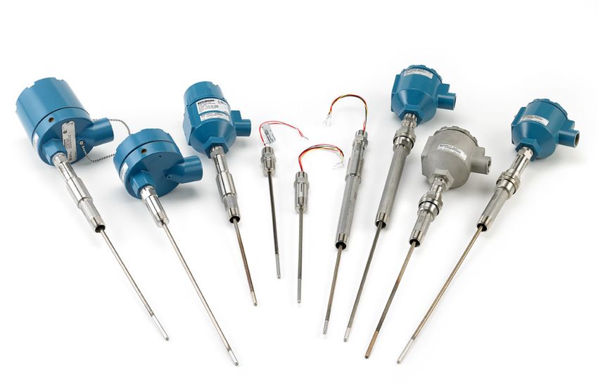
Rosemount™ 214C Temperature Sensors
Primary product benefits
High accuracy resistance temperature detectors (RTD) and various thermocouple types offered in a
variety of element configurations
Calibration capabilities for increased measurement accuracy for RTDs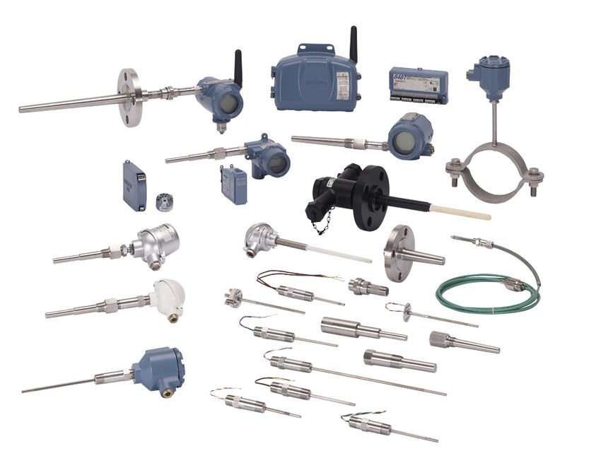
Rosemount 214C March 2019
Rosemount™ 214C Temperature Sensors
Optimize plant efficiency and increase measurement reliability with
industry-proven design and specifications
All sensor styles and lengths available as standard in 1/4-in. (6 mm) nominal diameter
State-of-the-art manufacturing processes providing robust element packaging, increasing reliability
Industry-leading calibration capabilities allowing for Callendar-Van Dusen values giving increased RTD accuracy when paired with
Rosemount transmitters
Optional Class A accuracy RTDs or Class 1/Special Tolerances thermocouples for critical temperature measurement points
Explore the benefits of a Complete Point Solution™ from Emerson™
“Transmitter assembled to sensor” and “Thermowell
assembled to sensor” options enable Emerson to provide a
complete point temperature solution, delivering
process-ready or hand-tight transmitter, sensor, and/or
thermowell assemblies
Complete portfolio of Single Point and Multi-Input
Temperature Measurement solutions, allowing effective
measurement and processes control with the trusted
reliability from Rosemount products
Experience global consistency and local support from numerous worldwide
Emerson manufacturing sites
World-class manufacturing provides globally consistent product from every factory
and the capacity to fulfill needs of any project, large or small
Experienced Instrumentation Consultants help select the right product for any
temperature application and offer advice on best installation practices
Extensive global network of Emerson service and support personnel can be on-site
when and where they are needed
Contents
Rosemount 214C Sensor . . . . . . . . . . . . . . . . . . . . . . . . . . . 3 Product certifications . . . . . . . . . . . . . . . . . . . . . . . . . . . . .31
RTD ordering information . . . . . . . . . . . . . . . . . . . . . . . . . . 4 Additional RTD specifications . . . . . . . . . . . . . . . . . . . . . .46
Thermocouple ordering information . . . . . . . . . . . . . . . 12 Additional thermocouple specifications . . . . . . . . . . . . .47
Ordering information detail . . . . . . . . . . . . . . . . . . . . . . . 20
2 Emerson.com/Rosemount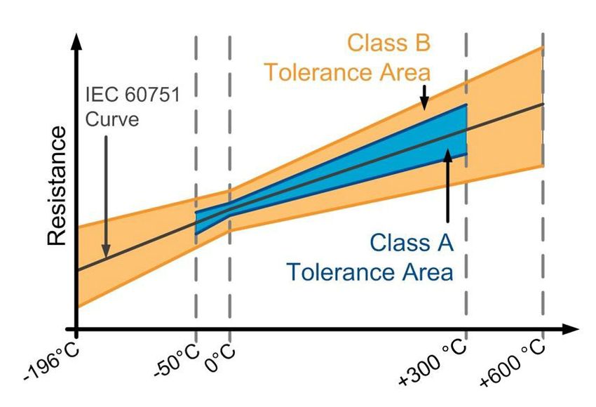
March 2019 Rosemount 214C
Rosemount 214C Sensor
The Rosemount 214C Sensors are designed to provide flexible and reliable temperature measurements in process monitoring and
control environments.
Features include:
Temperature ranges of –196 to 600 °C (–321 to 1112 °F) for RTDs and –196 to 1200 °C (–321 to 2192 °F) for thermocouples
Industry-standard sensor types: PT100 RTDs; thermocouple Type J, Type K, and Type T
Spring-loaded and compact spring-loaded sensor mounting styles
Hazardous location product approvals and certification
Calibration services to give insight to sensor performance
Calibration certificate to accompany sensor
Specification and selection of product materials, options, or components must be made by the purchaser of the equipment.
Figure 1. Model Number Ordering Example
Sensor
Sensor Sheath Sensor Number of Sensor insertion
Model Units mounting Options
type material accuracy elements length
style
2 1 4 C R W S M A 1 S 4 E 0 1 5 0 S L WR5, E5...
1 2 3 4 5 6 7 8 9 10 11 12 13 14 15 16 17 18 19 XXXXX
The numbers below the model string example in Figure 1 correlate to the character place numbers in the ordering table.
Ensure sensor fits thermowell
Rosemount 114C Head length (H) + Immersion length (U) = Rosemount 214C Sensor insertion length (L).
H U
L
Emerson.com/Rosemount 3
Rosemount 214C March 2019
RTD ordering information
Table 1. Rosemount 214C RTD Quick Order Table
Quick Order Table - RTD
2 1 4 C R
1 2 3 4 5 6 7 8 9 10 11 12 13 14 15 16 17 18 19 20...
316 SST material options
Sensor type M2 316 SST Components
Thin- lm; PT100; Sensor accuracy Product certification
T -50 to 450 °C Dimension units
(-58 to 842 °F) A1 Class A E5 USA Explosionproof
Sensor mounting style
B1 Class B English/U.S. Canada
Thin-film; PT100 E6
E customary units SL Spring loaded adapter Explosionproof
H -60 to 600 °C
(inches) See more options in
(-76 to 1112 °F) Adjustable spring xx
SA the full ordering table
M Metric units (mm) loaded fitting
Wire wound; PT100;
W -196 to 300 °C WA Welded adapter Connection heads
(-321 to 572 °F)
Rosemount Aluminum
Sensor insertion length
Sheath material Number of elements AR1 connection head with
0 to 78.5 inches; C1B1 1/2-in. NPT condult
SM 321 SST entry and instrument
S3 Single, 3-wire xxxx ¼-in. increments;
w/ English units connection
S4 Single, 4 -wire
Example Extensions types
D3 Dual, 3-wire 3.5 in = 0035;
50 in = 0500 UA Union Style
0 to 2000 mm; Extension length
xxxx 5mm increments;
w/ Metric units xx.x inches, 2.5 to 20
inches in ½-in.
Example Exxx
increments; w/ English
125 mm = 0125; Units
1300 mm = 1300
xxx mm, 65 to 500 mm
Exxx in 5-mm increments;
w/ Metric Units
Table 2. Rosemount 214C RTD Ordering Information
The starred offerings (★) represent the most common options and should be selected for best delivery. The non-starred offerings are subject
to additional delivery lead time.
Place #s
Model
1–4
★ 214C Temperature sensor core base model (made with standard outside diameter of 6 mm [1/4-in.])
Place #s Ref.
Sensor type Details
5–6 page
RTD, PT100; α = 0.00385; –50
★ RT Thin-film element is better in vibration and physical shock 21
to 450 °C (–58 to 842 °F)
RTD, PT100; α = 0.00385; –196
★ RW Wire wound element is better for low temperature applications 21
to 300 °C (–321 to 572 °F)
RTD, PT100; α = 0.00385; –60
★ RH High temperature thin-film element is better in vibration and physical shock 21
to 600 °C (–76 to 1112 °F)
Place #s
Sensor sheath material Details
7-8
★ SM 321 SST Maximum operating temperature limit of 816 °C (1500 °F) 23
4 Emerson.com/Rosemount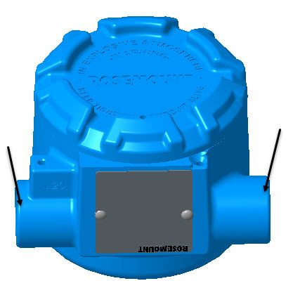
March 2019                                                                                                       Rosemount 214C

Table 2. Rosemount 214C RTD Ordering Information
The starred offerings (★) represent the most common options and should be selected for best delivery. The non-starred offerings are subject
to additional delivery lead time.
 Place #s                                                                                                                           Ref.
              Sensor accuracy                      Details                                                 Image
  9–10                                                                                                                              page

              Class A per IEC 60751 over
 ★ A1                                                                                                                                 24
              –50 to 300 °C (–58 to 572 °F)
                                                   Class A accuracy is only available
                                                   with wire-wound element Option
                                                   Code: RW
 ★ B1         Class B per IEC 60751                                                                                                   24

 Place #s
              Number of elements                   Details                                                 Image
  11–12

 ★ S3         Single, 3-wire                       Good measurement results                                                           25

                                                                                                                          Red
                                                                                                                          Red

 ★ S4         Single, 4-wire                       Excellent measurement results                                                      25

                                                                                                                          White
                                                                                                                          White

 ★ D3         Dual, 3-wire                         Added measurement redundancy                                                       25

  Place #
              Dimension units                      Details
    13
              English/U.S. customary units
 ★ E                                                                                                                                  26
              (inches)                             Only applies to lengths
 ★ M          Metric units (mm)                                                                                                       26

Emerson.com/Rosemount                                                                                                                      5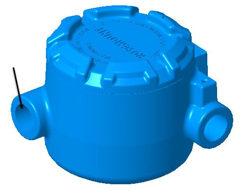
Rosemount 214C                                                                                                              March 2019

Table 2. Rosemount 214C RTD Ordering Information
The starred offerings (★) represent the most common options and should be selected for best delivery. The non-starred offerings are subject
to additional delivery lead time.
    Place #s                                                                                                                        Ref.
               Sensor insertion length (L)
     14–17                                                                                                                          page
               xxx.x inches, 0 to 78.5 inches in 1/4-in. increments (when ordered with Dimension units code E)
 ★ xxxx                                                                                                                               26
               Example of a 6.25-in. length where the second decimal is dropped off: 0062

               xxxx mm, 0 to 2000 mm in 5 mm increments (when ordered with Dimension units code M)
 ★ xxxx                                                                                                                               26
               Example of a 50 mm length: 0050
    Place #s                                                                                                                        Ref.
               Sensor mounting style(1)            Details                                                 Image
     18-19                                                                                                                          page

                                                   Ensures sensor contact with
 ★ SL          Spring loaded adapter                                                                                                  28
                                                   thermowell tip

                                                   Non-explosionproof adapter that is
                                                   1.17-in. (29.72 mm) shorter than
 ★ SC          Compact spring loaded adapter       standard spring loaded adapter                                                     28
                                                   (currently not available with
                                                   Division 2/Zone 2 approvals)
                                                   Spring loaded adapter with a small
               Spring loaded adapter with          opening on the side of the adapter
 ★ SW                                                                                                                                 28
               thermowell contact indication       for visual indication of sensor
                                                   contact with the tip of a thermowell
                                                   Welded joint between sensor
                                                   capsule and adapter allows for
                                                   direct immersion of sensor into the
 ★ WA          Welded adapter                                                                                                         29
                                                   process. If thermowell is used, this
                                                   welded joint acts as a secondary
                                                   process seal.
                                                   Non-explosionproof adapter that is
                                                   1.17-in. (29.72 mm) shorter than
 ★ WC          Compact welded adapter              standard welded adapter (currently                                                 29
                                                   not available with Division 2/Zone 2
                                                   approvals)
                                                   Adjustable fitting that allows for
                                                   installation along sensor capsule
 ★ SA          Adjustable spring loaded fitting    body. The spring loaded fitting                                                    29
                                                   ensures sensor contact to
                                                   thermowell tip.
 ★ CA          Compression fitting 1/8-in. NPT     Adjustable fitting that allows for
                                                   installation along the sensor
 ★ CB          Compression fitting 1/4-in. NPT     capsule body. (100 psig maximum.)
                                                                                                                                      30
 ★ CC          Compression fitting 1/2-in. NPT     (Default compression fitting
                                                   material is brass. For stainless steel,
 ★ CD          Compression fitting 3/4-in. NPT     select the M2 option.)
                                                   Sensor capsule without any fittings
 ★ SO          Sensor only                                                                                                            30
                                                   or adapters for mounting

6                                                                                                           Emerson.com/Rosemount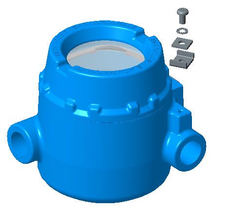
March 2019                                                                                                       Rosemount 214C

Table 2. Rosemount 214C RTD Ordering Information
The starred offerings (★) represent the most common options and should be selected for best delivery. The non-starred offerings are subject
to additional delivery lead time.

 Options (include with selected model number)
                                                                                                                                    Ref.
 316SST Material options                           Details                                                 Image
                                                                                                                                    page
                                                   Changes out the original 304SST
 ★ M1         316SST Wire on tag                   wire on tag to a corrosion-resistant                                               30
                                                   316SST wire on tag

                                                   Replaces various components with
                                                   corrosion-resistant 316SST material
 ★ M2         316SST Components                                                                                                       30
                                                   (review reference page for affected
                                                   components)

                                                                                                                                    Ref.
 Product certifications
                                                                                                                                    page
 ★ E1         ATEX Flameproof                                                                                                         32
 ★ I1         ATEX Intrinsic Safety                                                                                                   32
 ★ N1         ATEX Zone 2                                                                                                             32
 ★ ND         ATEX Dust Ignitionproof                                                                                                 32
 ★ E2         Brazil Flameproof                                                                                                       34
 ★ I2         Brazil Intrinsic Safety                                                                                                 34
 ★ E3         China Flameproof                                                                                                        34
 ★ I3         China Intrinsic Safety                                                                                                  35
 ★ N3         China Zone 2                                                                                                            35
 ★ E5         USA Explosionproof                                                                                                      31
 ★ N5         USA Division 2                                                                                                          31
 ★ E6         Canada Explosionproof                                                                                                   31
 ★ N6         Canada Division 2                                                                                                       31
 ★ E7         IECEx Flameproof                                                                                                        33
 ★ I7         IECEx Intrinsic Safety                                                                                                  33
 ★ N7         IECEx Zone 2                                                                                                            33
 ★ NK         IECEx Dust Ignitionproof                                                                                                33
 ★ EM         Technical Regulations Customs Union (EAC) Flameproof                                                                    36
 ★ IM         Technical Regulations Customs Union (EAC) Intrinsic Safety                                                              36
 ★ EP         Korea Flameproof                                                                                                        36
 ★ IP         Korea Intrinsic Safety                                                                                                  36
 ★ K1         Combination of ATEX Flameproof, Intrinsic Safety, Zone 2 and Dust Ignitionproof                                         36
 ★ K3         Combination of China Flameproof, Intrinsic Safety, Zone 2, and Dust Ignitionproof                                       36
 ★ K7         Combination of IECEx Flameproof, Intrinsic Safety, Zone 2, and Dust Ignitionproof                                       36

Emerson.com/Rosemount                                                                                                                      7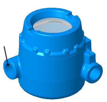
Rosemount 214C                                                                                                              March 2019

Table 2. Rosemount 214C RTD Ordering Information
The starred offerings (★) represent the most common options and should be selected for best delivery. The non-starred offerings are subject
to additional delivery lead time.
                                                                                                                                    Ref.
 Product certifications
                                                                                                                                    page
              Combination of Technical Regulations Customs Union (EAC) Flameproof, Intrinsic Safety, and Dust
 ★ KM                                                                                                                                 36
              Ignitionproof
 ★ KP         Combination of Korea Flameproof, Intrinsic Safety, and Dust Ignitionproof                                               36
 ★ KA         Combination of ATEX Flameproof and Canada Explosionproof                                                                36
 ★ KB         Combination of USA and Canada Explosionproof                                                                            36
 ★ KC         Combination of ATEX Flameproof and USA Explosionproof                                                                   36
 ★ KD         Combination of ATEX Flameproof, USA and Canada Explosionproof                                                           36
 ★ KE         Combination of ATEX and IECEx Flameproof, USA and Canada Explosionproof                                                 36
 ★ KN         Combination of ATEX and IECEx Zone 2, and USA and Canada Division 2                                                     36
                                                                                                                                    Ref.
 Connection heads                                  Details                                                 Image
                                                                                                                                    page

                                                    • Conduit connection: 1/2-in. NPT; M20
                                                    • Instrument connection: 1/2-in. NPT
                                                    • Optional terminal block, stainless
 ★ AR1        Rosemount aluminum                                                                                                      37
                                                      steel cover chain, external ground
                                                      screw, or low temperature options
                                                      also available

                                                    • Conduit connection: 1/2-in. NPT; M20
                                                    • Instrument connection: 1/2-in. NPT
              Rosemount aluminum with
 ★ AR2                                              • Optional terminal block, external                                               37
              display cover                           ground screw, or low temperature
                                                      options also available

                                                    • Conduit connection: 1/2-in. NPT; M20
                                                    • Instrument connection: 1/2-in. NPT
                                                    • Optional terminal block, stainless
 ★ SR1        Rosemount SST                                                                                                           37
                                                      steel cover chain, external ground
                                                      screw, or low temperature options
                                                      also available

                                                    • Conduit connection: 1/2-in. NPT; M20
                                                    • Instrument connection: 1/2-in. NPT
              Rosemount SST with display
 ★ SR2                                              • Optional terminal block, external                                               37
              cover                                   ground screw, or low temperature
                                                      options also available

                                                    • Conduit connection: 3/4-in. NPT
                                                    • Instrument connection: 1/2-in. NPT
 ★ AT1        Aluminum with terminal strip                                                                                            37
                                                    • Optional stainless steel cover chain or
                                                      external ground screw available

8                                                                                                           Emerson.com/Rosemount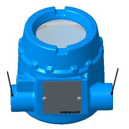
March 2019                                                                                                       Rosemount 214C

Table 2. Rosemount 214C RTD Ordering Information
The starred offerings (★) represent the most common options and should be selected for best delivery. The non-starred offerings are subject
to additional delivery lead time.
                                                                                                                                    Ref.
 Connection heads                                  Details                                                 Image
                                                                                                                                    page

                                                    • Conduit connection: 3/4-in. NPT
              Aluminum with terminal strip          • Instrument connection: 1/2-in. NPT
 ★ AT3                                                                                                                                38
              and extended cover                    • Optional stainless steel cover chain or
                                                      external ground screw available

                                                    • Conduit connection: 1/2-in. NPT or
                                                      M20
              Universal 3 entry aluminum            • Instrument connection 1/2-in. NPT
 ★ AJ1                                                                                                                                38
              junction box                          • Optional terminal block, external
                                                      ground screw, and stainless steel
                                                      cover chain available

                                                    • Conduit connection: 1/2-in. NPT or
                                                      M20
              Universal 3 entry aluminum            • Instrument connection 1/2-in. NPT
 ★ AJ2                                                                                                                                38
              junction box with display cover       • Optional terminal block, external
                                                      ground screw, and stainless steel
                                                      cover chain available

                                                                                                                                    Ref.
 Conduit entry (selection required for connection heads)                                                   Image
                                                                                                                                    page
                                                   Available for connection head
 ★ C1          / -in. NPT
              1 2                                                                                                                     38
                                                   options AR1, AR2, SR1, and SR2
                                                   Available for connection head
 ★ C2         M20 ⫻ 1.5                                                                                                               38
                                                   options AR1, AR2, SR1, and SR2
                                                   Available for connection head
 ★ C3          / -in. NPT
              3 4                                                                                                                     38
                                                   options AT1 and AT3

                                                                                                                                    Ref.
 Instrument connection (selection required for connection heads)                                           Image
                                                                                                                                    page

 ★ B1          / -in. NPT
              1 2                                                                                                                     39

                                                                                                                                    Ref.
 Conduit cable glands                                                                                      Image
                                                                                                                                    page

 ★ GN1        Ex d, standard cable diameter                                                                                           39

 ★ GN2        Ex d, thin cable diameter                                                                                               39

 ★ GN6        EMV, standard cable diameter                                                                                            39

Emerson.com/Rosemount                                                                                                                      9
Rosemount 214C                                                                                                              March 2019

Table 2. Rosemount 214C RTD Ordering Information
The starred offerings (★) represent the most common options and should be selected for best delivery. The non-starred offerings are subject
to additional delivery lead time.

 ★ GP1        Ex e, standard cable diameter, polyamide                                                                                39

 ★ GP2        Ex e, thin cable diameter, polyamide                                                                                    39

                                                                                                                                    Ref.
 Extension type                                    Details                                                 Image
                                                                                                                                    page
                                                   Contains union fitting, which allows
              Union style, 1/2-in. NPT,            orientation of the conduit entry
 ★ UA         1/2-in. NPT
                                                                                                                                      40
                                                   during installation; also known as
                                                   nipple-union style
                                                   Contains coupling fitting which
              Fixed style, 1/2-in. NPT,            does not allow orientation of the
 ★ FA         1/2-in. NPT
                                                                                                                                      40
                                                   conduit entry during installation;
                                                   also known as nipple-coupling style
                                                                                                                                    Ref.
 Extension length (E)
                                                                                                                                    page
 ★ Exxx       xx.x inches, 2.5 to 20 inches in 1/2-in. increments (when ordered with Dimension units code E)                          40
 ★ Exxx       xxx mm, 65 to 500 mm in 5 mm increments (when ordered with Dimension units code M)                                      40
                                                                                                                                    Ref.
 Single point calibration
                                                                                                                                    page
 ★ X91Q4      Resistance of one specified temperature point                                                                           42
                                                                                                                                    Ref.
 Temperature range calibration
                                                                                                                                    page
 ★ V20Q4      32 to 212 °F (0 to 100 °C)                                                                                              43
 ★ V21Q4      32 to 392 °F (0 to 200 °C)                                                                                              43
 ★ V22Q4      32 to 842 °F (0 to 450 °C)                                                                                              43
 ★ V23Q4      32 to 1112 °F (0 to 600 °C)                                                                                             43
 ★ V24Q4      –58 to 212 °F (–50 to 100 °C)                                                                                           43
 ★ V25Q4      –58 to 392 °F (–50 to 200 °C)                                                                                           43
 ★ V26Q4      –58 to 842 °F (–50 to 450 °C)                                                                                           43
 ★ V27Q4      –76 to 1112 °F (–60 to 600 °C)                                                                                          43
 ★ X8Q4       Custom specified temperature range                                                                                      43
                                                                                                                                    Ref.
 Ground screw                                      Details                                                 Image
                                                                                                                                    page

                                                   Allows for grounding of wires to the
 ★ G1         External ground screw                                                                                                   44
                                                   connection head

10                                                                                                          Emerson.com/Rosemount
March 2019 Rosemount 214C
Table 2. Rosemount 214C RTD Ordering Information
The starred offerings (★) represent the most common options and should be selected for best delivery. The non-starred offerings are subject
to additional delivery lead time.
Ref.
Cover chain Details Image
page
Keeps the cover connected to the
connection head when
★ G3 Cover chain 44
disassembled; not available with
display covers
Ref.
Terminal block Details Image
page
Available if wire termination in a
★ TB Terminal block 44
connection head is required
Ref.
Low temperature housing
page
★ LT Low temperature connection head option down to –51 °C (–60 °F) 44
Ref.
Transmitter assembled to sensor Details
page
Process-ready assembly of Ensures sensor is threaded into connection head with transmitter and
★ XA 45
transmitter and sensor torqued for process-ready installation; sensor is wired to the transmitter
Hand-tight assembly of Ensures sensor is threaded into connection head with transmitter but only
★ XC 45
transmitter and sensor hand tightened; manual wiring is required
Ref.
Thermowell assembled to sensor Details
page
Process-ready assembly of Ensures sensor is threaded into thermowell and torqued for process-ready
★ XW 45
sensor and thermowell installation
Hand-tight assembly of sensor
★ XT Ensures sensor is threaded into thermowell but only hand tightened 45
and thermowell
Ref.
Extended product warranty Details
page
★ WR3 3-year limited warranty This warranty option is to extend your manufacturers warranty to three or 45
★ WR5 5-year limited warranty five years for manufacturer related defects 45
1. Welded adapters are built several millimeters shorter than specified length to ensure that the sheath will not be damaged by contact with the bottom of a
thermowell if overtightened. Conversely, spring loaded adapters are built several millimeters longer than specified to ensure contact with the bottom of a
thermowell.
Emerson.com/Rosemount 11Rosemount 214C March 2019
Thermocouple ordering information
Table 3. Rosemount 214C Thermocouple Quick Order Table
2 1 4 C T
1 2 3 4 5 6 7 8 9 10 11 12 13 14 15 16 17 18 19 20...
316 SST material options
Sensor type M2 316 SST Components
Thermocouple Type J Sensor accuracy Product certification
J -40 to 760 °C Dimension units
(-40 to 1400 °F) T1 Class 1 E5 USA Explosionproof
Sensor mounting style
T2 Class 2 English/U.S. Canada
Thermocouple Type K E6
E customary units SL Spring loaded adapter Explosionproof
K -40 to 1200 °C SP Special Tolerances (inches) See more options in
(-40 to 2192 °F) Adjustable spring xx
ST Standard Tolerances SA the full ordering table
M Metric units (mm) loaded fitting
Thermocouple Type T
T -196 to 370 °C WA Welded adapter Connection heads
(-321 to 698 °F)
Rosemount Aluminum
Sensor insertion length
Sheath material Number of elements AR1 connection head with
0 to 78.5 inches; C1B1 1/2-in. NPT condult
SM 321 SST entry and instrument
SG Single, grounded xxxx ¼-in. increments;
w/ English units connection
AK Alloy 600 (Type K SU Single, ungrounded
only) Example Extensions types
DG Dual, grounded, 3.5 in = 0035;
un-isolated 50 in = 0500; UA Union Style
Dual, ungrounded,
DU 0 to 2000 mm; Extension length
isolated xxxx 5 mm increments;
w/ Metric units xx.x inches, 2.5 to 20
inches in ½-in.
Example Exxx
increments; w/ English
125 mm = 0125; units
1300 mm = 1300
xxx mm, 65 to 500
mm in 5-mm
Exxx
increments; w/ Metric
units
Table 4. Rosemount 214C Thermocouple Ordering Information
The starred offerings (★) represent the most common options and should be selected for best delivery. The non-starred offerings are subject
to additional delivery lead time.
Place #s
Model
1–4
★ 214C Temperature thermocouple sensor core base model (made with standard outside diameter of 6mm [1/4-in.])
Place #s Ref.
Sensor type Details
5–6 page
Thermocouple Type J, One of the most common thermocouples made of conductor materials Iron and
★ TJ 22
–40 to 760 °C (–40 to 1400 °F) Constantan
Commonly used for high temperature applications, Type K thermocouples
Thermocouple Type K,
★ TK contain Chromel® and Alumel® conductors (available with sheath material 23
–40 to 1200 °C (–40 to 2192 °F)
Option AK only)
Thermocouple Type T, Commonly used for low temperature applications, Type T thermocouples
★ TT 23
–196 to 370 °C (–321 to 698 °F) contain copper and constantan conductors
12 Emerson.com/RosemountMarch 2019 Rosemount 214C
Table 4. Rosemount 214C Thermocouple Ordering Information
The starred offerings (★) represent the most common options and should be selected for best delivery. The non-starred offerings are subject
to additional delivery lead time.
Place #s Ref.
Sensor sheath material Details
7–8 page
Maximum operating temperature limit of 816 °C (1500 °F) (For types TJ and TT
★ SM 321 SST 23
only)
★ AK(1) Alloy 600 Maximum operating temperature limit of 1200 °C (2192 °F) (For type TK only) 24
Place #s Ref.
Sensor accuracy Details
9–10 page
Approximately half of accuracy error margin than Class 2; made with higher
★ T1 Class 1 per IEC 60584 25
grade wire which increases accuracy reading
Wider accuracy error margin than Class 1; made with standard thermocouple
★ T2 Class 2 per IEC 60584 25
grade wire
Special Tolerances per ASTM Approximately half of accuracy error margin than Standard Tolerances; made
★ SP 25
E230 with higher grade wire which increases the accuracy reading
Standard Tolerances per ASTM Wider accuracy error margin than Special Tolerances; made with standard
★ ST 25
E230 thermocouple grade wire
Place #s Ref.
Number of elements Details Image
11–12 page
Provides contact to sheath for faster
response time than a single,
★ SG Single, grounded ungrounded thermocouple; more 26
susceptible to induced noise from
ground loops
Provides more accurate reading than a
★ SU Single, ungrounded single grounded thermocouple, with a 26
slower response time
Provides faster response time than a
dual ungrounded isolated
★ DG Dual, grounded, unisolated 26
thermocouple with added
redundancy in the reading
Provides more accurate reading than a
dual grounded unisolated
★ DU Dual, ungrounded, isolated 26
thermocouple, with a slower response
time
Place # Ref.
Dimension units Details
13 page
English/U.S. customary units
★ E 26
(inches) Only applies to lengths
★ M Metric units (mm) 26
Emerson.com/Rosemount 13Rosemount 214C March 2019
Table 4. Rosemount 214C Thermocouple Ordering Information
The starred offerings (★) represent the most common options and should be selected for best delivery. The non-starred offerings are subject
to additional delivery lead time.
Place #s Ref.
Sensor insertion length (L)
14-17 page
xxx.x-in. 0 to 78.5-in. in 1/4-in. increments (when ordered with Dimension units code E)
★ xxxx 26
Example of a 6.25-in. length where the second decimal is dropped off: 0062
xxxx mm, 0 to 2000 mm in 5 mm increments (when ordered with Dimension units code M)
★ xxxx 26
Example of a 50 mm length: 0050
Place #s Ref.
Sensor mounting style(2) Details Image
18–19 page
Ensures sensor contact with
★ SL Spring loaded adapter 28
thermowell tip
Non-explosionproof adapter that is
1.17-in. (29.72 mm) shorter than
★ SC Compact spring loaded adapter standard spring loaded adapter 28
(currently not available with
Division 2/Zone 2 approvals)
Spring loaded adapter with a small
Spring loaded adapter with opening on the side of the adapter for
★ SW 28
thermowell contact indication visual indication of sensor contact
with the tip of a thermowell
Welded joint between sensor capsule
and adapter allows for direct
★ WA Welded adapter immersion of sensor into the process. 29
If thermowell is used, this welded joint
acts as a secondary process seal.
Non-explosionproof adapter that is
1.17-in. (29.72 mm) shorter than
★ WC Compact welded adapter standard welded adapter (currently 29
not available with Division 2/Zone 2
approvals)
Adjustable fitting that allows for
installation along sensor capsule
★ SA Adjustable spring loaded fitting body. The spring loaded fitting 29
ensures sensor contact to thermowell
tip.
★ CA Compression fitting 1/8-in. NPT Adjustable fitting that allows for
installation along the sensor capsule
★ CB Compression fitting 1/4-in. NPT body.(Default compression fitting
30
★ CC Compression fitting 1/2-in. NPT material is brass. For stainless steel,
select the M2 option.) (100 psig
★ CD Compression fitting 3/4-in. NPT maximum.)
Sensor capsule without any fittings or
★ SO Sensor only 30
adapters for mounting
14 Emerson.com/RosemountMarch 2019 Rosemount 214C
Table 4. Rosemount 214C Thermocouple Ordering Information
The starred offerings (★) represent the most common options and should be selected for best delivery. The non-starred offerings are subject
to additional delivery lead time.
Options (include with selected model number)
Ref.
316SST Material options Details Image
page
Changes out the original 304SST wire
★ M1 316SST Wire on tag on tag to a corrosion-resistant 316SST 30
wire on tag
Replaces various components with
corrosion-resistant 316SST material
★ M2 316SST Components 30
(review reference page for affected
components)
Ref.
Product certifications
page
★ E1 ATEX Flameproof 32
★ I1 ATEX Intrinsic Safety 32
★ N1 ATEX Zone 2 32
★ ND ATEX Dust Ignitionproof 32
★ E2 Brazil Flameproof 34
★ I2 Brazil Intrinsic Safety 34
★ E3 China Flameproof 34
★ I3 China Intrinsic Safety 35
★ N3 China Zone 2 35
★ E5 USA Explosionproof 31
★ N5 USA Division 2 31
★ E6 Canada Explosionproof 31
★ N6 Canada Division 2 31
★ E7 IECEx Flameproof 33
★ I7 IECEx Intrinsic Safety 33
★ N7 IECEx Zone 2 33
★ NK IECEx Dust Ignitionproof 33
★ EM Technical Regulations Customs Union (EAC) Flameproof 36
★ IM Technical Regulations Customs Union (EAC) Intrinsic Safety 36
★ EP Korea Flameproof 36
★ IP Korea Intrinsic Safety 36
★ K1 Combination of ATEX Flameproof, Intrinsic Safety, Zone 2 and Dust Ignitionproof 36
★ K3 Combination of China Flameproof, Intrinsic Safety, Zone 2, and Dust Ignitionproof 36
★ K7 Combination of IECEx Flameproof, Intrinsic Safety, Zone 2, and Dust Ignitionproof 36
Emerson.com/Rosemount 15Rosemount 214C March 2019
Table 4. Rosemount 214C Thermocouple Ordering Information
The starred offerings (★) represent the most common options and should be selected for best delivery. The non-starred offerings are subject
to additional delivery lead time.
Ref.
Product certifications
page
★ KM Combination of Technical Regulations Customs Union (EAC) Flameproof, Intrinsic Safety, and Dust Ignitionproof 36
★ KP Combination of Korea Flameproof, Intrinsic Safety, and Dust Ignitionproof 36
★ KA Combination of ATEX Flameproof and Canada Explosionproof 36
★ KB Combination of USA and Canada Explosionproof 36
★ KC Combination of ATEX Flameproof and USA Explosionproof 36
★ KD Combination of ATEX Flameproof, USA and Canada Explosionproof 36
★ KE Combination of ATEX and IECEx Flameproof, USA and Canada Explosionproof 36
★ KN Combination of ATEX and IECEx Zone 2, and USA and Canada Division 2 36
Ref.
Connection heads Details Image
page
• Conduit connection: 1/2-in. NPT; M20
• Instrument connection: 1/2-in. NPT
★ AR1 Rosemount aluminum • Optional terminal block, stainless steel 37
cover chain, external ground screw, or
low temperature options also available
• Conduit connection: 1/2-in. NPT; M20
• Instrument connection: 1/2-in. NPT
Rosemount aluminum with
★ AR2 • Optional terminal block, external 37
display cover ground screw, or low temperature
options also available
• Conduit connection: 1/2-in. NPT; M20
• Instrument connection: 1/2-in. NPT
★ SR1 Rosemount SST • Optional terminal block, stainless steel 37
cover chain, external ground screw, or
low temperature options also available
• Conduit connection: 1/2-in. NPT; M20
• Instrument connection: 1/2-in. NPT
Rosemount SST with display
★ SR2 • Optional terminal block, external 37
cover ground screw, or low temperature
options also available
• Conduit connection: 3/4-in. NPT
• Instrument connection: 1/2-in. NPT
★ AT1 Aluminum with terminal strip 37
• Optional stainless steel cover chain or
external ground screw available
16 Emerson.com/RosemountMarch 2019 Rosemount 214C
Table 4. Rosemount 214C Thermocouple Ordering Information
The starred offerings (★) represent the most common options and should be selected for best delivery. The non-starred offerings are subject
to additional delivery lead time.
Ref.
Connection heads Details Image
page
• Conduit connection: 3/4-in. NPT
Aluminum with terminal strip • Instrument connection: 1/2-in. NPT
★ AT3 38
and extended cover • Optional stainless steel cover chain or
external ground screw available
• Conduit connection: 1/2-in. NPT or M20
• Instrument connection 1/2-in. NPT
Universal 3 entry aluminum
★ AJ1 • Optional terminal block, external 37
junction box ground screw, and stainless steel cover
chain available
• Conduit connection: 1/2-in. NPT or M20
• Instrument connection 1/2-in. NPT
Universal 3 entry aluminum
★ AJ2 • Optional terminal block, external 37
junction box with display cover ground screw, and stainless steel cover
chain available
Ref.
Conduit entry (selection required for connection heads) Image
page
Available for connection head options
★ C1 / -in. NPT
1 2 38
AR1, AR2, SR1, and SR2
Available for connection head options
★ C2 M20 ⫻ 1.5 38
AR1, AR2, SR1, and SR2
Available for connection head options
★ C3 / -in. NPT
3 4 38
AT1 and AT3
Ref.
Instrument connection (selection required for connection heads) Image
page
★ B1 / -in. NPT
1 2 39
Ref.
Conduit cable glands Image
page
★ GN1 Ex d, standard cable diameter 39
★ GN2 Ex d, thin cable diameter 39
★ GN6 EMV, standard cable diameter 39
Emerson.com/Rosemount 17Rosemount 214C March 2019
Table 4. Rosemount 214C Thermocouple Ordering Information
The starred offerings (★) represent the most common options and should be selected for best delivery. The non-starred offerings are subject
to additional delivery lead time.
Ref.
Conduit cable glands Image
page
★ GP1 Ex e, standard cable diameter, polyamide 39
★ GP2 Ex e, thin cable diameter, polyamide 39
Ref.
Extension type Details Image
page
Contains union fitting which allows
Union style, 1/2-in. NPT, orientation of the conduit entry
★ UA 1/2-in. NPT
40
during installation; also known as
nipple-union style
Contains coupling fitting which does
Fixed style, 1/2-in. NPT, not allow orientation of the conduit
★ FA 1/2-in. NPT
40
entry during installation; also known
as nipple-coupling style
Ref.
Extension length (E)
page
★ Exxx xx.x-in., 2.5 to 20-in. in 1/2-in. increments (when ordered with Dimension units code E) 40
★ Exxx xxx mm, 65 to 500 mm in 5 mm increments (when ordered with Dimension units code M) 40
Ref.
Ground screw Details Image
page
Allows for grounding of wires to the
★ G1 External ground screw 44
connection head
Ref.
Cover chain Details Image
page
Keeps the cover connected to the
★ G3 Cover chain connection head when disassembled; 44
not available with display covers
Ref.
Terminal block Details Image
page
Available if wire termination in a
★ TB Terminal block 44
connection head is required
18 Emerson.com/RosemountMarch 2019 Rosemount 214C
Table 4. Rosemount 214C Thermocouple Ordering Information
The starred offerings (★) represent the most common options and should be selected for best delivery. The non-starred offerings are subject
to additional delivery lead time.
Ref.
Low temperature housing
page
★ LT Low temperature connection head option down to –51 °C (–60 °F) 44
Ref.
Transmitter assembled to sensor Details
page
Process-ready assembly of Ensures sensor is threaded into connection head with transmitter and torqued
★ XA 45
transmitter and sensor for process-ready installation; sensor is wired to the transmitter
Hand-tight assembly of Ensures sensor is threaded into connection head with transmitter but only hand
★ XC 45
transmitter and sensor tightened; manual wiring is required
Ref.
Thermowell assembled to sensor Details
page
Process-ready assembly of Ensures sensor is threaded into thermowell and torqued for process-ready
★ XW 45
sensor and thermowell installation
Hand-tight assembly of sensor
★ XT Ensures sensor is threaded into thermowell but only hand tightened 45
and thermowell
Ref.
Extended product warranty Details
page
★ WR3 3-year limited warranty This warranty option is to extend your manufacturers warranty to three or five 45
★ WR5 5-year limited warranty years for manufacturer related defects 45
1. For type TK only.
2. Welded adapters are built several millimeters shorter than specified length to ensure that the sheath will not be damaged by contact with the bottom of a thermowell if
overtightened. Conversely, spring loaded adapters are built several millimeters longer than specified to ensure contact with the bottom of a thermowell.
Emerson.com/Rosemount 19Rosemount 214C March 2019 Ordering information detail Sensor type Back to RTD ordering table Back to Thermocouple ordering table RTD RTDs are based on the principle that the electrical resistance of a metal increases as temperature increases – a phenomenon known as thermal resistivity. Thus, a temperature measurement can be inferred by measuring the resistance of the RTD element. RTDs are constructed of a resistive material with leads attached and usually placed into a protective sheath (see “Sheath material” on page 23 for details). The resistive material can be a variety of materials. Emerson however, standardizes on platinum materials for all RTDs because of its high accuracy, excellent repeatability, and exceptional linearity over a wide temperature range. Platinum RTDs also exhibit a large resistance change per degree of temperature change. The relationship between the resistance change of an RTD vs. temperature is called its Temperature Coefficient of Resistance (TCR) and is often referred to as the RTD's alpha curve. Emerson's PT100 RTDs all have a standard alpha coefficient of α = 0.00385 which is the most popular option that is recognized nationally and internationally. Reference Figure 2 for typical behavior of the resistance of a platinum RTD over a range of temperature. Figure 2. Resistance Change vs. Temperature for Platinum RTD (PT100) Emerson offers the two most common styles of RTD sensors: thin-film and wire-wound. Wire-wound RTDs are manufactured by winding the resistive wire in a helical shape supported in a ceramic sheath – hence the name wire-wound. Thin-film RTDs are manufactured with a thin resistive coating that is deposited on a flat, usually rectangular ceramic substrate. 20 Emerson.com/Rosemount
March 2019                                                                                                 Rosemount 214C

Figure 3. RTD Elements
                            Thin-film                                                      Wire-wound

Thin-film RTD (RT, RH)
Thin-film elements are generally better in vibration and physical shock. With a platinum construction (PT100) and a temperature
coefficient α =0.00385, these elements can be rated between –60 to 600 °C (–76 to 1112 °F).

Wire-wound RTD (RW)
When a lower temperature range is required for an RTD, the wire-wound element is a better choice. The RW option code is for
wire-wound RTDs which are for –196 to 300 °C (–321 to 572 °F). Similar to the thin-film element, this element has a platinum
construction (PT100) and an alpha value of α =0.00385. Because of its lower temperature range, this option should be chosen for
low temperature applications (below –60 °C [–76 °F]).

Table 5. RTD Comparison
 Option code                          RT                         RW                           RH

 Element type                      Thin film                Wire wound            High temperature thin film
                                 –50 to 450 °C             –196 to 300 °C                –60 to 600 °C
 Temperature range
                                (–58 to 842 °F)           (–321 to 572 °F)              (–76 to 1112 °F)
                                                                                      Higher temperature
                             Higher vibration and      Higher accuracy and low
 Good for                                                                         applications, resistance to
                                physical shock        temperature applications
                                                                                 vibration, and physical shock
 Accuracy                           Class B                Class A; Class B                 Class B

Emerson.com/Rosemount                                                                                                             21
Rosemount 214C March 2019
Thermocouple
A thermocouple (T/C) is a closed-circuit thermoelectric temperature sensing device consisting of two wires of dissimilar metals
joined at both ends. A current is created when the temperature at one end or junction differs from the temperature at the other end.
This phenomenon is known as the Seebeck effect, which is the basis for thermocouple temperature measurements.
One end is referred to as the hot junction whereas the other end is referred to as the cold junction. The hot junction measuring
element is placed inside a sensor sheath and exposed to the process. The cold junction, or the reference junction, is the termination
point outside of the process where the temperature is known and where the voltage is being measured (e.g. in a transmitter, control
system input card, or other signal conditioner).
According to the Seebeck effect, a voltage measured at the cold junction is proportional to the difference in temperature between
the hot junction and the cold junction. This voltage may be referred to as the Seebeck voltage, thermoelectric voltage, or
thermoelectric EMF. As the temperature rises at the hot junction, the observed voltage at the cold junction also increases
non-linearly with the rising temperature. The linearity of the temperature-voltage relationship depends on the combination of
metals used to make the T/C.
There are many types of T/C that use various metal combinations. These combinations have different output characteristics that
define the applicable temperature range it can measure and the corresponding voltage output. The higher the magnitude of the
voltage output the higher the measurement resolution, which increases repeatability and accuracy. There are trade-offs between
measurement resolutions and temperature ranges which suits individual T/C types to specific ranges and applications. Refer to
Figure 4 for different thermocouple behavior over a range of temperatures.
Figure 4. Thermocouple Temperature Ranges
Performance Range (°C)
1000
1200
-200
200
400
600
800
Type
0
Type J Thermocouple
Type K Thermocouple
Type T Thermocouple
-200
200
600
1000
1400
1800
2200
Performance Range (°F)
Emerson offers a variety of thermocouples: Type J, Type K, and Type T.
Type J (TJ)
Figure 5. Type J Thermocouple Colors
ASTM color codes IEC color codes
Constructed of iron and constantan, Type J thermocouples have a potential temperature range of –40 to 760 °C (–40 to 1400 °F), and
a sensitivity of about 50 μ V/ °C. Type J thermocouples becomes brittle below 0 °C (32 °F) and are suitable for use in vacuum,
reducing, or inert atmospheres. These thermocouples will have a reduced life if used in an oxidizing atmosphere.
22 Emerson.com/RosemountMarch 2019 Rosemount 214C
Type K (TK)
Figure 6. Type K Thermocouple Colors
ASTM color codes IEC color codes
Constructed of Chromel and Alumel materials, Type K thermocouples are one of the most common general purpose thermocouples,
have a potential temperature range of –40 to 1200 °C (–40 to 2192 °F), and a sensitivity of approximately 41 μ V/ °C. Type K
thermocouples are relatively linear and may be used in continuously oxidizing or neutral atmospheres, and are typically used above
538 °C (1000 °F).
Type T (TT)
Figure 7. Type T Thermocouple Colors
ASTM color codes IEC color codes
Constructed of copper and constantan, Type T thermocouples have a potential temperature range of –196 to 370 °C (–321 to 698 °F)
and a sensitivity of 38 μ V/ °C. Type T thermocouples demonstrate a good linearity and can be used in oxidizing, reducing or inert
atmospheres, as well as in a vacuum. These thermocouples exhibit a high resistance to moisture corrosion, and are typically used in
very low (cryogenic) to medium temperature ranges.
Table 6. Thermocouple Types
Option code TJ TK TT
Element type Type J Type K Type T
Metals Iron-constantan Chromel-Alumel Copper-constantan
–40 to 760 °C –40 to 1200 °C –196 to 370 °C
Temperature range
(–40 to 1400 °F) (–40 to 2192 °F) (–321 to 698 °F)
Good for Medium temperature ranges High temperature ranges Low (cryogenic) temperature ranges
Sheath material
Back to RTD ordering table
Back to Thermocouple ordering table
(SM)
For Type J and T thermocouples, Emerson offers a protective sheath made of 321 SST. This material is a stainless steel stabilized by
adding titanium. This gives it excellent resistance to intergranular corrosion after exposure to high temperatures (above 427 °C [800
°F]). Type 321 has a maximum operating temperature limit of 816 °C (1500 °F). The operating temperature range for the sensor
element will constrain this limit. See Table 5 and Table 6 for the temperature range of the different sensor element types. This
material is only available for Type J and T thermocouple.
Emerson.com/Rosemount 23Rosemount 214C March 2019
(AK)
For Type K thermocouples, Emerson offers a protective sheath made of Alloy 600. This material is a nickel-chromium alloy with good
oxidation resistance at higher temperatures. Alloy 600 is designed for use in the temperature range of –40 to 1200 °C
(–40 to 2192 °F). The operating temperature range for the sensor element will be constrained by this limit.This material is only
available for Type K thermocouples.
Sensor accuracy
Back to RTD ordering table
Back to Thermocouple ordering table
(A1, B1)
The thin-film option codes RT and RH are available in Class B accuracy only.
The wire-wound option code RW is intended for applications that require high accuracy and/or subjected to low temperatures.
Option code RW is available with both Class A and Class B accuracy over –50 to 300 °C (–58 to 572 °F).
Table 7 shows the interchangeability of RTD sensors. It explains the tolerance for Class A and Class B accuracy RTDs over a specific
temperature range. The performance of the option codes RT and RW sensors conform to the standard set by IEC 60751. Figure 8 is a
graphical representation that demonstrates the Class A and Class B accuracy curve over temperature per IEC 60751. For maximum
system accuracy, Emerson can provide sensor calibration and optional sensor-to-transmitter matching obtainable through the use of
Callendar-Van Dusen constants. See “Calibration” on page 42 for additional calibration offering.
Table 7. Interchangeability Error for RTD per IEC 60751
°C (°F) Tolerance in °C (°F)
Class B for RTD Model Class B for RTD Model Class A for RTD Model Class B for RTD Model
Option RT Option RW Option RW Option RH
-196 (-321) N/A ±1.28 (2.30) N/A N/A
-100 (-148) N/A ±0.8 (1.44) N/A N/A
-50 (-58) ±0.55 (0.99) ±0.55 (0.99) ±0.25 (0.45) ±0.55 (0.99)
0 (32) ±0.3 (0.54) ±0.3 (0.54) ±0.15 (0.27) ±0.3 (0.54)
100 (212) ±0.8 (1.44) ±0.8 (1.44) ±0.35 (0.63) ±0.8 (1.44)
200 (392) ±1.3 (2.34) ±1.3 (2.34) ±0.55 (0.99) ±1.3 (2.34)
300 (572) ±1.8 (3.24) ±1.8 (3.24) ±0.75 (1.35) ±1.8 (3.24)
450 (842) ±2.55 (4.59) N/A N/A ±2.55 (4.59)
500 (932) N/A N/A N/A ±2.8 (5.04)
600 (1112) N/A N/A N/A ±3.3 (5.94)
Figure 8. Sensor Accuracy Curve
24 Emerson.com/RosemountMarch 2019 Rosemount 214C
(T1, T2, SP, ST)
Similar to RTDs, thermocouples also can have tolerances as defined by national standards. According to IEC 60584, thermocouples
can have a narrower tolerance (or higher accuracy) of Class 1. Class 1 thermocouples are manufactured with higher grade wire which
increases their accuracy reading. Class 2, on the other hand, has a wider accuracy error margin since they are manufactured with
standard thermocouple grade wires.
Emerson also provides thermocouples that meet tolerances per ASTM E230 standards. Special Tolerances are approximately half of
accuracy error margin than Standard Tolerances since they are made with higher grade wire.
Number of elements
Back to RTD ordering table
Back to Thermocouple ordering table
(S3, S4, D3)
For applications where a generic RTD temperature measurement is sufficient, select option S3 for a single, 3-wire measurement. For
better results, select option S4 for a single, 4-wire measurement. For added measurement reassurance, select option D3 for a dual,
3-wire measurement.
Since the lead wires are part of the RTD circuit, the lead wire resistance needs to be compensated for to achieve the best accuracy.
This becomes especially critical in applications where long sensor and/or lead wires are used. Emerson provides two lead wire
configurations that are commonly available: 3-wire and 4-wire.
In a 4-wire configuration, the lead wire resistance is inconsequential to the measurement. It uses a measurement technique where a
very small constant current of about 150 μA is applied to the sensor through two leads and the voltage developed across the sensor is
measured over the other two wires with a high-impedance and high resolution measuring circuit. In accordance with Ohm’s Law the
high impedance virtually eliminates any current flow in the voltage measurement leads and therefore the resistance of the leads is
not a factor.
In a 3-wire configuration, compensation is accomplished using a third wire with the assumption that it will be the same resistance as
the other two wires and the same compensation is applied to all three wires.
Lead wire configurations can be programmed in Emerson's Rosemount Temperature Transmitters since they are capable of
compensating for the various configurations.
All of the available lead wire configurations conform to IEC 60751. As a result, the wire colors for the sensor match what is defined by
the standard.
A 4-wire sensor can also be used in a 2- or 3- wire configuration. To properly wire the 4-wire RTD for use in a 2-, 3-, or 4-wire
configuration, refer to the Rosemount 214C Quick Start Guide.
Figure 9. RTD Lead Wire Configurations
Single element, 3-wire (S3) Single element, 4-wire (S4) Dual element, 3-wire (D3)
Red
Red
White
White
Emerson.com/Rosemount 25Rosemount 214C March 2019
(SG, SU, DG, DU)
For generic thermocouple measurements, select option SG for a single, grounded junction thermocouple measurement. This
grounded configuration provides contact to the sheath for faster response time; however, this is more susceptible to induced noise
from ground loops. This can be avoided by selecting option SU for single, ungrounded thermocouple configuration. This particular
type provides a more accurate reading than a single, grounded thermocouple, but with a slower response time due to it's isolation.
For added redundancy in the temperature measurement, select option DG for dual, grounded, unisolated configuration; or option
DU for dual, ungrounded, isolated sensor wire configuration. See Figure 10 for all available configurations.
Figure 10. Thermocouple Lead Wire Configurations
Single, grounded (SG) Single, ungrounded (SU)
Dual, grounded, unisolated (DG) Dual, ungrounded, isolated (DU)
Dimension units
Back to RTD ordering table
Back to Thermocouple ordering table
These dimensional units determine both the sensor insertion length and the extension length through the model.
English/U.S. customary units (E)
If English/U.S. customary units is selected, then all lengths will be in inches.
Metric (M)
If metric is selected, then all lengths will be in millimeters.
Sensor insertion length
Back to RTD ordering table
Back to Thermocouple ordering table
Sensor insertion length can be ordered by specifying a four-digit option code. However, when ordering, the second decimal place is
dropped off.
When ordering in inches, the length can be ordered in 1/4-in. increments. Here are some examples:
120.25-in. = 1202
62.75 -in. = 0627
26 Emerson.com/RosemountMarch 2019 Rosemount 214C
When ordering in millimeters, the length can be ordered in 5 mm increments. Here are some examples:
50 mm = 0050
325 mm = 0325
Determining the length (L) of a replacement spring-loaded sensor in existing installation
To replace only the sensor
1. Remove the existing sensor from the installation.
2. Measure the sensor length with the spring in the relaxed state from the tip of the sensor to the thread engagement point of
13 mm (0.5-in.) into the adapter threads.
3. Subtract 6 mm (0.25-in.) from your measurement. The resulting length is (L). Use this length to specify the sensor insertion
length in the ordering table.
To replace the sensor and extension
1. Remove the existing sensor and extension from the installed thermowell.
2. Measure the sensor length with the spring in the relaxed state from the tip of the sensor to the thread engagement point of
13 mm (0.5-in.) into the extension threads.
3. Subtract 6 mm (0.25-in.) from your measurement. The resulting length is (L). Use this length to specify the sensor insertion
length in the ordering table.
4. Measure the extension length from thermowell connection to the adapter/fitting connection accounting for 13 mm (0.5-in.)
thread engagement. The resulting length is (E). Use this length to specify the extension length in the ordering table (see
“Extension length” on page 40).
Note
Emerson standardizes on a spring compression of 13 mm (0.5-in.) for all spring loaded and compact spring loaded mounting styles
for sensors. The thermowell tip thickness is assumed to be 6 mm (0.25-in.) and the sensors are built 6 mm (0.25-in.) longer than the
ordered length to ensure contact to the thermowell tip.
To ensure sensor fits the Rosemount 114C Thermowell, refer to “Ensure sensor fits thermowell” on page 3.
Emerson.com/Rosemount 27Rosemount 214C March 2019 Sensor mounting style Back to RTD ordering table Back to Thermocouple ordering table Emerson offers a variety of mounting style options for every sensor. Depending on the application needs and constraints, a certain type of mounting style may be preferred. See description of each style and their dimensions below. Threaded style mounting adapters The threaded style is a sensor with a threaded adapter to provide a connection to the process and connection head. The benefit of the threaded style is the ability to install it directly into a process or thermowell without any additional mounting fittings. Emerson currently offers two different threaded mounting styles: Spring loaded adapter and Compact spring loaded adapter. Spring loaded adapter (SL) A spring located in the threaded adapter allows the sensor to travel, ensuring contact with the bottom of a thermowell. This helps ensure better sensor accuracy, improved sensor response time and aids in providing better performance while under vibration. Figure 11. Dimensions Compact spring loaded adapter (SC) When space is limited, Emerson provides a compact spring loaded adapter. This adapter has a length of 29.21 mm (1.15-in.) as shown in Figure 12. It is also an excellent option for when explosionproof approvals are not a concern yet continuous contact to the thermowell tip is required. Figure 12. Dimensions Spring loaded adapter with thermowell contact indication (SW) This spring loaded adapter contains a small opening on the side of the adapter giving this design an added advantage of a visual indication of the sensor contact to the tip of the thermowell. This design is slightly larger with a length of 66.04 mm (2.60-in.). Figure 13. Dimensions 28 Emerson.com/Rosemount
March 2019                                                                                                        Rosemount 214C

Welded adapter (WA)
Unlike the spring loaded style, the welded adapter does not contain a spring in the design. Instead, the
mounting adapter is welded to the body of the sensor that creates a seal when immersed directly into
the process. This seal is rated for 3500 psi.

Figure 14. Dimensions

Compact welded adapter (WC)
Similar size as the compact spring loaded adapter, the compact welded adapter does not contain a spring
and the mounting adapter is instead welded to the body of the sensor. This adapter has a length of
29.21 mm (1.15-in.).

Figure 15. Dimensions

Adjustable spring loaded fitting (SA)
A spring located in the adjustable threaded compression fitting allows the sensor to travel ensuring contact
to the bottom of a thermowell. As a result, this adjustable fitting allows for installation along the body of a
sensor capsule that can be of any length.

Figure 16. Dimensions

Emerson.com/Rosemount                                                                                                         29
Rosemount 214C March 2019 Compression fittings (CA, CB, CC, CD) An adjustable fitting that allows for installation along the body of a sensor capsule. This limits the need to stock various lengths of sensors. Instead it only requires to insert the sensor in the process or thermowell, adjust the fitting to length and tighten it on to the sensor sheath; allowing for quick set temperature measurement points. Note Default compression fitting material is brass. For stainless steel, select the M2 option. For low pressure applications— 100 psig maximum. Sensor only (SO) Sensor capsule without any fittings or adapters. 316SST Material options (M1, M2) Back to RTD ordering table Back to Thermocouple ordering table The M1 option changes out the original 304SST wire on tag to a corrosion resistant 316SST wire on tag while the M2 option changes out the following components: Wire on tag Adapter Union Nipple Name plate Drive screws Conduit cable glands Compression fittings The components listed above are replaced with corrosion resistant 316SST components. 30 Emerson.com/Rosemount
March 2019                                                                                                         Rosemount 214C

Product certifications
Back to RTD ordering table
Back to Thermocouple ordering table

Rev 1.21

European Directive Information                                                Markings: NI CL I, DIV 2, GP A, B, C, D; T6
                                                                                        (–50 °C ≤ Ta ≤ +80 °C), T5 (–50 °C ≤ Ta ≤ +95 °C);
A copy of the EU Declaration of Conformity can be found at the                          installed per Rosemount drawing 00214-1030;
end of the Quick Start Guide. The most recent revision of the EU                        Type 4X† and IP 66/67; Vmax 35VDC,
Declaration of Conformity can be found at                                               750 mWmax
Emerson.com/Rosemount.

Ordinary Location Certification                                          E6   Canada Explosionproof (XP) & Dust Ignitionproof (DIP)

The Rosemount 214C has been examined and tested to                            Certificate: 70044744
determine that the design meets the basic electrical,                         Standards: CAN/CSA C22.2 No. 0:2010, CAN/CSA No.
mechanical, and fire protection requirements by a nationally                             25-1966 (R2000), CAN/CSA C22.2 No.
recognized test laboratory (NRTL) as accredited by the Federal                           30-M1986 (R2012), CAN/CSA C22.2 No.
Occupational Safety and Health Administration (OSHA).                                    94-M1991 (R2011), CAN/CSA C22.2 No.
                                                                                         61010-1:2012
North America
                                                                              Markings: XP CL I, DIV 1, GP B, C, D; DIP CL II, DIV 1, GP E, F,
The US National Electrical Code® (NEC) and the Canadian                                 G; CL III; T6 (–50 °C ≤ Ta ≤ +80 °C), T5 (–50 °C ≤ Ta
Electrical Code (CEC) permit the use of Division marked                                 ≤ +95 °C); Seal not required; installed per
equipment in Zones and Zone marked equipment in Divisions.                              Rosemount drawing 00214-1030; Type 4X† and
The markings must be suitable for the area classification, gas,                         IP 66/67; Vmax 35 VDC,
and temperature class. This information is clearly defined in the                       750 mWmax
respective codes.
                                                                         Special Conditions for Safe Use (X):
                                                                           1. Flameproof joints are not intended for repair.
USA                                                                        2. Cable entries must be used which maintain the ingress
E5    USA Explosionproof (XP) and Dust-Ignitionproof (DIP)                    protection of the enclosure. Unused cable entries must be
                                                                              filled with suitable blanking plugs.
      Certificate: 70044744
                                                                         N6 Canada Division 2
      Standards: FM 3600:2011, FM 3615:2006, UL 50E:2007, UL
                  61010-1:2010, ANSI/ISA 60529:2004                           Certificate: 70044744
      Markings: XP CL I, DIV 1, GP B, C, D; DIP CL II, DIV 1, GP E, F,        Standards: : CAN/CSA C22.2 No. 0:2010, CAN/CSA C22.2
                G; CL III; T6 (–50 °C ≤ Ta ≤ +80 °C),                                     No. 94-M1991 (R2011), CAN/CSA No.
                T5 (–50 °C ≤ Ta ≤ +95 °C); Seal not required;                             213-M1987 (R2013), CAN/CSA C22.2 No.
                installed per Rosemount drawing 00214-1030;                               61010-1:2012
                Type 4X† and IP 66/67; Vmax 35 VDC,                           Markings: CL I, DIV 2, GP A, B, C, D; T6 (–50 °C ≤ Ta ≤
                750 mWmax                                                               +80 °C), T5 (–50 °C ≤ Ta ≤ +95 °C); Seal not
                                                                                        required; installed per Rosemount drawing
Special Conditions for Safe Use (X):                                                    00214-1030; Type 4X† and IP 66/67; Vmax
  1. Flameproof joints are not intended for repair.                                     35 VDC, 750 mWmax
  2. Cable entries must be used which maintain the ingress               † – Spring loaded indicator has reduced ingress and dust ratings.
     protection of the enclosure. Unused cable entries must be               Spring loaded sensors must be installed in a thermowell to
     filled with suitable blanking plugs.                                    maintain dust and ingress ratings. Unpainted aluminum
                                                                             enclosures are Type 4 rated.
                                                                         *Assembly is not Canada Explosionproof (E6) rated to Group B if
N5 USA Division 2 (NI)                                                     a 0079 connection head is used
      Certificate: 70044744
      Standards: FM 3600:2011, FM 3611:2004, UL 50E:2007, UL
                  61010-1:2010, ANSI/ISA 60529:2004

Emerson.com/Rosemount                                                                                                                      31
You can also read