AXI BFM Cores v5.0 LogiCORE IP Product Guide - Vivado Design Suite
←
→
Page content transcription
If your browser does not render page correctly, please read the page content below
AXI BFM Cores v5.0

LogiCORE IP Product Guide

Vivado Design Suite
PG129 October 1, 2014
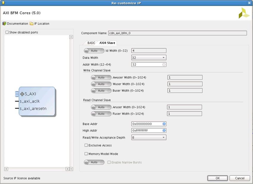
Table of Contents
       IP Facts

       Chapter 1: Overview
          Core Architecture. . . . . . . . . . . . . . . . . . . . . . . . . . . . . . . . . . . . . . . . . . . . . . . . . . . . . . . . . . . . . . . . . .       5
          Configuration Options . . . . . . . . . . . . . . . . . . . . . . . . . . . . . . . . . . . . . . . . . . . . . . . . . . . . . . . . . . . . . .          7
          Applications . . . . . . . . . . . . . . . . . . . . . . . . . . . . . . . . . . . . . . . . . . . . . . . . . . . . . . . . . . . . . . . . . . . . . .   7
          BFM Limitations . . . . . . . . . . . . . . . . . . . . . . . . . . . . . . . . . . . . . . . . . . . . . . . . . . . . . . . . . . . . . . . . . . .      7
          Licensing and Ordering Information . . . . . . . . . . . . . . . . . . . . . . . . . . . . . . . . . . . . . . . . . . . . . . . . . . .                   8

       Chapter 2: Product Specification
          Standards . . . . . . . . . . . . . . . . . . . . . . . . . . . . . . . . . . . . . . . . . . . . . . . . . . . . . . . . . . . . . . . . . . . . . . . . 9

       Chapter 3: Designing with the Core
          AXI BFM Cores Design Parameters . . . . . . . . . . . . . . . . . . . . . . . . . . . . . . . . . . . . . . . . . . . . . . . . . . . 10
          Test Writing API . . . . . . . . . . . . . . . . . . . . . . . . . . . . . . . . . . . . . . . . . . . . . . . . . . . . . . . . . . . . . . . . . . 24
          Protocol Description . . . . . . . . . . . . . . . . . . . . . . . . . . . . . . . . . . . . . . . . . . . . . . . . . . . . . . . . . . . . . . 52

       Chapter 4: Design Flow Steps
          Customizing and Generating the Core . . . . . . . . . . . . . . . . . . . . . . . . . . . . . . . . . . . . . . . . . . . . . . . .                        53
          Constraining the Core . . . . . . . . . . . . . . . . . . . . . . . . . . . . . . . . . . . . . . . . . . . . . . . . . . . . . . . . . . . . .            65
          Simulation . . . . . . . . . . . . . . . . . . . . . . . . . . . . . . . . . . . . . . . . . . . . . . . . . . . . . . . . . . . . . . . . . . . . . .     66
          Synthesis and Implementation . . . . . . . . . . . . . . . . . . . . . . . . . . . . . . . . . . . . . . . . . . . . . . . . . . . . . .                   66

       Chapter 5: Example Design
          Overview . . . . . . . . . . . . . . . . . . . . . . . . . . . . . . . . . . . . . . . . . . . . . . . . . . . . . . . . . . . . . . . . . . . . . . . 67
          Using AXI BFM Cores for Standalone RTL Design. . . . . . . . . . . . . . . . . . . . . . . . . . . . . . . . . . . . . . . . 68

       Chapter 6: Test Bench
          AXI3 BFM Example Test Bench and Test . . . . . . . . . . . . . . . . . . . . . . . . . . . . . . . . . . . . . . . . . . . . . .                           69
          AXI4 BFM Example Test Bench and Test . . . . . . . . . . . . . . . . . . . . . . . . . . . . . . . . . . . . . . . . . . . . . .                           70
          AXI4-Lite BFM Example Test Bench and Test . . . . . . . . . . . . . . . . . . . . . . . . . . . . . . . . . . . . . . . . . . .                            71
          AXI4-Stream BFM Example Test Bench and Test . . . . . . . . . . . . . . . . . . . . . . . . . . . . . . . . . . . . . . . .                                72
          Useful Coding Guidelines and Examples . . . . . . . . . . . . . . . . . . . . . . . . . . . . . . . . . . . . . . . . . . . . . .                          73

AXI BFM Cores v5.0                                                www.xilinx.com                                                Send Feedback
                                                                                                                                                                     2
PG129 October 1, 2014
Appendix A: Verification, Compliance, and Interoperability

       Appendix B: Migrating and Upgrading
          Migrating to the Vivado Design Suite. . . . . . . . . . . . . . . . . . . . . . . . . . . . . . . . . . . . . . . . . . . . . . . . . 78
          Upgrading in the Vivado Design Suite . . . . . . . . . . . . . . . . . . . . . . . . . . . . . . . . . . . . . . . . . . . . . . . . 78

       Appendix C: Debugging
          Finding Help on Xilinx.com . . . . . . . . . . . . . . . . . . . . . . . . . . . . . . . . . . . . . . . . . . . . . . . . . . . . . . . . . 79
          Interface Debug . . . . . . . . . . . . . . . . . . . . . . . . . . . . . . . . . . . . . . . . . . . . . . . . . . . . . . . . . . . . . . . . . . 81

       Appendix D: Additional Resources and Legal Notices
          Xilinx Resources . . . . . . . . . . . . . . . . . . . . . . . . . . . . . . . . . . . . . . . . . . . . . . . . . . . . . . . . . . . . . . . . . .     82
          References . . . . . . . . . . . . . . . . . . . . . . . . . . . . . . . . . . . . . . . . . . . . . . . . . . . . . . . . . . . . . . . . . . . . . .   82
          Revision History . . . . . . . . . . . . . . . . . . . . . . . . . . . . . . . . . . . . . . . . . . . . . . . . . . . . . . . . . . . . . . . . . .     83
          Please Read: Important Legal Notices . . . . . . . . . . . . . . . . . . . . . . . . . . . . . . . . . . . . . . . . . . . . . . . .                     85

AXI BFM Cores v5.0                                                www.xilinx.com                                                Send Feedback
                                                                                                                                                                   3
PG129 October 1, 2014
IP Facts

Introduction                                                             LogiCORE IP Facts Table
                                                                              Core Specifics
The Xilinx® LogiCORE™ IP AXI Bus Functional
                                                     Supported                 UltraScale™ Architecture, Zynq®-7000 All
Model (BFM) cores, developed for Xilinx by           Device Family (1)                     Programmable SoC, 7 Series
Cadence® Design Systems, support the                 Supported User
                                                                                      AXI4, AXI4-Lite, AXI4-Stream, AXI3
simulation of customer-designed AXI-based IP.        Interfaces
AXI BFM cores support all versions of AXI (AXI3,     Resources                                                     N/A
AXI4, AXI4-Lite, and AXI4-Stream). The BFMs
                                                                           Provided with Core
are encrypted Verilog modules. BFM operation
                                                     Design Files                                                  N/A
is controlled by using a sequence of Verilog
tasks contained in a Verilog-syntax text file.       Example Design                                              Verilog

                                                     Test Bench                                                  Verilog
                                                     Constraints File                                              N/A

Features                                             Simulation
                                                     Model
                                                                                                      Encrypted Verilog

•   Supports all protocol data widths and            Supported
                                                                                                                   N/A
                                                     S/W Driver
    address widths, transfer types and
    responses                                                            Tested Design Flows(2)(3)
                                                                                                  Vivado® Design Suite
•   Transaction-level protocol checking (burst       Design Entry
                                                                                                    Vivado IP Integrator
    type, length, size, lock type, cache type)
                                                                                      For supported simulators, see the
                                                     Simulation
                                                                             Xilinx Design Tools: Release Notes Guide.
•   Behavioral Verilog Syntax
                                                     Synthesis                                                     N/A
•   Verilog Task-based API
                                                                                 Support
                                                              Provided by Xilinx @ www.xilinx.com/support

                                                     Notes:
                                                     1. For a complete list of supported derivative devices, see
                                                        the Vivado IP catalog.
                                                     2. Windows XP 64-bit is not supported.
                                                     3. For the supported versions of the tools, see the
                                                        Xilinx Design Tools: Release Notes Guide.
                                                     4. This IP does not deliver BFM for Zynq PS. It only delivers
                                                        the BFM cores for AXI3, AXI4, AXI4-Lite, and AXI4-Stream
                                                        interfaces.

AXI BFM Cores v5.0                          www.xilinx.com                         Send Feedback                 4
PG129 October 1, 2014                                                                        Product Specification
Chapter 1

Overview

       Core Architecture
       The general AXI BFM core architecture is shown in Figure 1-1.
       X-Ref Target - Figure 1-1

                                                                  $;,%)0

                                                             &RQILJXUDWLRQ
                                                            )XQFWLRQ$3,
                                                             &KDQQHO$3,
                                                           6LJQDO,QWHUIDFH
                                                    Figure 1-1:    Core Architecture

       All of the AXI BFM cores consist of three main layers:

       •                   Signal interface
       •                   Channel API
       •                   Function API

       The signal interface includes the typical Verilog input/output ports and associated signals.
       The channel API is a set of defined Verilog tasks (see Test Writing API) that operate at the
       basic transaction level inherent in the AXI protocol, including:

       •                   Read Address Channel
       •                   Write Address Channel
       •                   Read Data Channel
       •                   Write Data Channel
       •                   Write Response Channel

       This split enables the tasks associated with each channel to be executed concurrently or
       sequentially. This allows the test writer to control and implement out-of-order transfers,
       interleaved data transfers, and other features.

AXI BFM Cores v5.0                                     www.xilinx.com                  Send Feedback
                                                                                                       5
PG129 October 1, 2014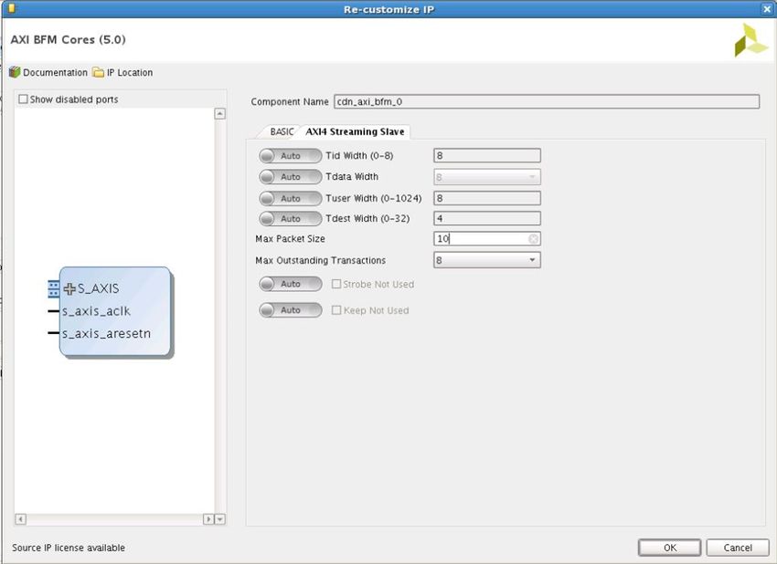
Chapter 1: Overview

       The next level up in the API hierarchy is the function level API (see Test Writing API). This
       level has complete transaction level control. For example, a complete AXI read burst process
       is encapsulated in a single Verilog task.

       An important component of the AXI BFM core architecture is the configuration mechanism.
       This is implemented using Verilog parameters and/or BFM internal variables and is used to
       set the address bus width, data bus width, and other parameters. The reason Verilog
       parameters are used instead of defines is so that each BFM can be configured separately
       within a single test bench.

       For example, it is reasonable to have an AXI master that has a different data bus width than
       one of the slaves it is attached to (in this case the interconnect needs to handle this). BFM
       internal variables are used for configuration variables that maybe changed during
       simulation. For a complete list of configuration options, see Configuration Options.

       The intended use of the AXI BFM cores are shown in Figure 1-2.
       X-Ref Target - Figure 1-2

                                                                7HVWY
                                                      7HVWEHQFKY

                                                                    $;,%)0

                                                                &RQILJXUDWLRQ
                                                                )XQFWLRQ$3,
                                                                                      7HVW3URJUDP
                                                                &KDQQHO$3,
                                   &ORFNDQG5HVHW            6LJQDO,QWHUIDFH
                                      *HQHUDWRU

                                                                     '87

                                               Figure 1-2:   AXI BFM Cores Use Case

       Figure 1-2 shows a single AXI BFM core. However, the test bench can contain multiple
       instances of AXI BFM core. The DUT and the AXI BFM core are instantiated in a test bench
       that also contains a clock and reset generator. Then, the test writer instantiates the test
       bench into the test module and creates a test program using the BFM API layers. The test
       program would call API tasks either sequentially or concurrently using fork and join. See
       Chapter 5, Example Design and Chapter 6, Test Bench for practical examples of test
       programs and test bench setups.

AXI BFM Cores v5.0                                      www.xilinx.com                  Send Feedback
                                                                                                            6
PG129 October 1, 2014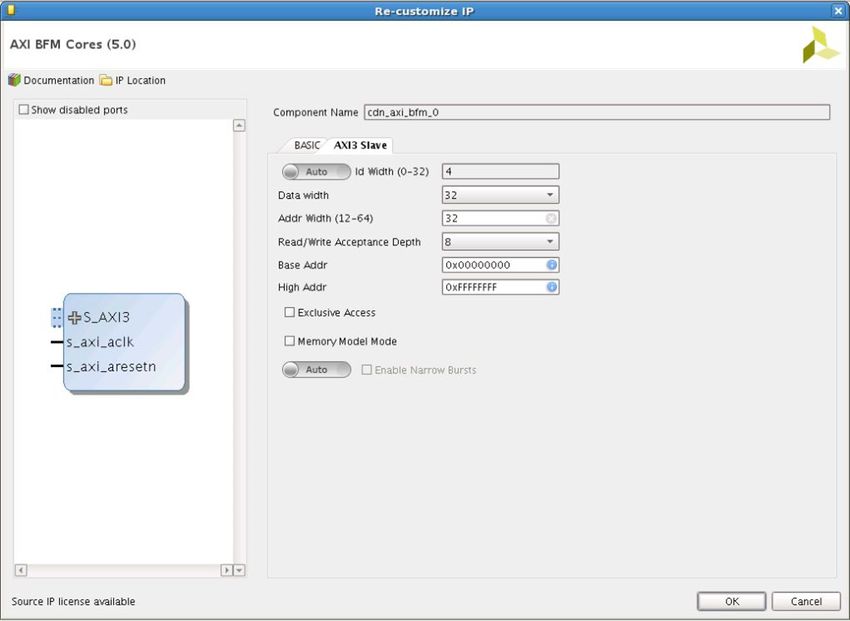
Chapter 1: Overview

       Configuration Options
       In most cases, the configuration options are passed to the AXI BFM cores through Verilog
       parameters. AXI BFM core internal variables are used for options that can be dynamically
       controlled by the test writer because Verilog parameters do not support run time
       modifications.

       To change the AXI BFM core internal variables during simulation, the correct BFM API task
       should be called. For example, to change the CHANNEL_LEVEL_INFO from 0 to 1, the
       set_channel_level_info(1)task call should be made. For more information on the
       API for changing internal variables, see Test Writing API.

       Applications
       The purpose of the AXI BFM cores are to verify connectivity and basic functionality of AXI
       masters and AXI slaves. A basic level of protocol checking is included with the AXI BFM
       cores. For comprehensive protocol checking, the Cadence AXI UVC [Ref 1] should be
       deployed.

       The following aspects of the AXI3 and AXI4 protocol are checked by the AXI BFM cores:

       •   Reset conditions are checked:

           °   Reset values of signals

           °   Synchronous release of reset
       •   Inputs into the test writing API are checked to ensure they are valid to prevent protocol
           violations.
       •   Signal inputs into master and slave BFM, respectively, are checked to ensure they are
           valid to prevent protocol violations.
       •   Address ranges are checked in the Slave BFM.

       This section describes the checkers that are implemented as Verilog tasks.

       BFM Limitations
       The purpose of this IP is to enable Xilinx customers to verify that their designs are able to
       communicate with Xilinx IP using AXI3 or AXI4 protocol. The complete verification of such
       interfaces with regards to protocol compliance is not within the scope of the AXI BFM cores;
       for compliance testing and complete verification of AXI interfaces then the Cadence AXI
       UVC should be deployed.

AXI BFM Cores v5.0                         www.xilinx.com                     Send Feedback
                                                                                                    7
PG129 October 1, 2014
Chapter 1: Overview

       The BFM cores are implemented in behavioral Verilog-2001 and as such are limited to the
       constructs available for this version of Verilog. For that reason, some of the checking might
       seem limited compared with other VIP offerings that can leverage from assertion languages
       like SVA or PSL. Furthermore, there are no constructs inside Verilog-2001 to prevent or
       handle test bench race conditions. This means that the test writer must ensure that they are
       not causing race conditions by calling the Function Level API tasks within concurrent blocks
       (for example, inside a fork... join block). It is possible to use the concurrent blocks to create
       certain scenarios as illustrated in the example tests provided with this VIP.

       The most common protocol violation caused by such race conditions is violation of the AXI3
       write ordering rules: the first write transfer of each burst MUST be in the same order as the
       address phase transfers that is. the WID of the first transfer in each burst must be in the
       same order as the associated AWIDs. This is an incredibly difficult check to write in
       Verilog-2001 but a limited debug check is available to help detect and debug such a
       condition (see the function "set_write_id_order_check_feature_value" in Section
       5 for more details on how to enable this).

       Another limitation for BFM is that AXI Master BFM does not allow the same ID for
       outstanding transactions. Each outstanding transaction must be given an unique ID.

       The BFM cores are encrypted using the Verilog P1735 IEEE standard. End users should note
       that while there are no import/export restrictions on this verification IP there maybe be a
       need for the correct simulator license feature for 256-bit AES decryption.

       Licensing and Ordering Information
       This Xilinx ® LogiCORE™ IP module is provided under the terms of the Xilinx Core License
       Agreement. The module is shipped as part of the Vivado ® Design Suite. For full access to all
       core functionalities in simulation, you must purchase a license for the core. Contact your
       local Xilinx sales representative for information on pricing and availability.

       For more information, visit the AXI Bus Functional Model web page.

       Information about other Xilinx LogiCORE IP modules is available at the Xilinx Intellectual
       Property page. For information on pricing and availability of other Xilinx LogiCORE IP
       modules and tools, contact your local Xilinx sales representative.

       IMPORTANT: When simulating AXI BFM cores, the license is checked out and held until the simulation
       is completed.

AXI BFM Cores v5.0                          www.xilinx.com                        Send Feedback
                                                                                                        8
PG129 October 1, 2014
Chapter 2

Product Specification

       Standards
       The AXI BFM cores are AXI4, AXI4-Lite, AXI4-Stream, and AXI3 compliant.

AXI BFM Cores v5.0                      www.xilinx.com                    Send Feedback
                                                                                          9
PG129 October 1, 2014
Chapter 3

Designing with the Core
        This chapter includes guidelines and additional information to facilitate designing with the
        core.

        AXI BFM Cores Design Parameters
        Note: Run Time Parameters can also be changed during simulation from test bench using respective
        APIs.

        AXI3 BFM
        AXI3 Master BFM
        Table 3-1 contains a list of parameters and configuration variables supported by the AXI3
        Master BFM.

Table 3-1:   AXI3 Master BFM Parameters
BFM Parameters                       Description
                                            Static Parameters
                                     String name for the master BFM. This is used in the messages coming
NAME
                                     from the BFM. The default for the master BFM is “MASTER_0.”
                                     Read and write data buses can be 32, 64, 128, 256, 512, or 1,024 bits
DATA_BUS_WIDTH                       wide.
                                     Default is 32.
ADDRESS_BUS_WIDTH                    This parameter can take the values from 12 to 64. Default is 32.
ID_BUS_WIDTH                         Default is 4.
                                     This defines the maximum number of outstanding transactions. Any
                                     attempt to generate more traffic while this limit has been reached is
MAX_OUTSTANDING_TRANSACTIONS         handled by stalling until at least one of the outstanding transactions has
                                     finished.
                                     Default is 8.

AXI BFM Cores v5.0                           www.xilinx.com                           Send Feedback
                                                                                                             10
PG129 October 1, 2014
Chapter 3: Designing with the Core
Table 3-1: AXI3 Master BFM Parameters (Cont’d)
BFM Parameters Description
This parameter informs the master that exclusive access is supported by
the slave. A value of 1 means it is supported so the response check
expects an EXOKAY, or else give a warning, in response to an exclusive
EXCLUSIVE_ACCESS_SUPPORTED
access. A value of 0 means the slave does not support this so a response
of OKAY is expected in response to an exclusive access.
Default is 1.
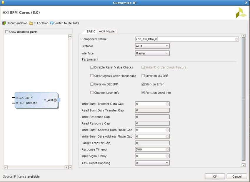
Run Time Parameters
The configuration variable can be set dynamically during the run of a
test. It controls the gap between the write data transfers that comprise
a write data burst. This value is an integer number and is measured in
clock cycles.
WRITE_BURST_DATA_TRANSFER_GAP Default is 0.
Note: If this is set to a value greater than zero and concurrent write bursts are
called. Then write data interleaving occurs. The depth of this data interleaving
depends on the number of parallel writes being performed. Care must be taken
to ensure that write order protocol is not violated by the test writer.
This value, measured in clock cycles, is the value used to determine if a
task that is waiting for a response should timeout.
RESPONSE_TIMEOUT
Default is 500 clock cycles.
A value of zero means that the timeout feature is disabled.
This configuration value is used to enable/disable the checks for the
reset values of input signals to the BFM. For example, the slave BFM
DISABLE_RESET_VALUE_CHECKS
checks at reset time if the signals from the master are at the expected
reset values.
This configuration variable is used to enable/disable the stopping of the
simulation on an error condition.
STOP_ON_ERROR
The default (1) means stop on error.
Note: This is not used for timeout errors; such errors always stop simulation.
This configuration variable controls the printing of channel level
information messages. When set to 1 info messages are printed, when
CHANNEL_LEVEL_INFO
set to zero no channel level information is printed.
Default (0) means channel level info messages are disabled.
This configuration variable controls the printing of function level
information messages. When set to 1 info messages are printed, when
FUNCTION_LEVEL_INFO
set to zero no function level information is printed.
Default (1) means function level info messages are enabled.
This configuration value is used to enable/disable the setting of BFM
CLEAR_SIGNALS_AFTER_HANDSHAKE output signals to reset values between transfers.
Default is 0.
This configuration value can be used to disable the write ID ordering
WRITE_ID_ORDER_CHECK_FEATURE
checks which might be required for error testing.
This configuration value is used to enable/disable errors on SLVERR
responses to reads or writes.
ERROR_ON_SLVERR
Default is 0, which means these are reported as warnings instead of
errors.
AXI BFM Cores v5.0 www.xilinx.com Send Feedback
11
PG129 October 1, 2014Chapter 3: Designing with the Core
Table 3-1: AXI3 Master BFM Parameters (Cont’d)
BFM Parameters Description
This configuration value is used to enable/disable errors on SLVERR
responses to reads or writes.
ERROR_ON_DECERR
Default is 0, which means these are reported as warnings instead of
errors.
This is used to move the BFM input signals off the simulation clock edge
INPUT_SIGNAL_DELAY
if needed. The default is 0.
0 = ignore reset and continue to process task (default)
1 = stall task execution until out of reset and print info message
TASK_RESET_HANDLING
2 = issue an error and stop (depending on STOP_ON_ERROR value)
3 = issue a warning and continue
AXI3 Slave BFM
Table 3-2 contains a list of parameters and configuration variables supported by the AXI3
Slave BFM:
Table 3-2: AXI3 Slave BFM Parameters
BFM Parameters Description
Static Parameters
String name for the slave BFM. This is used in the messages coming from
NAME
the BFM. The default for the slave BFM is “SLAVE_0.”
Read and write data buses can be 32, 64, 128, 256, 512, or 1,024 bits
DATA_BUS_WIDTH wide.
Default is 32.
ADDRESS_BUS_WIDTH Address parameter takes the values from 12 to 64. Default is 32.
Slaves can have different ID bus widths compared to the master. The
ID_BUS_WIDTH
default is 4.
SLAVE_ADDRESS This is the start address of the slave memory range.
This is the size of the memory that the slave models. Starting from
address = SLAVE_ADDRESS.
SLAVE_MEM_SIZE
This is measured in bytes therefore a value of 4,096 = 4 KB.
The default value is 4 bytes, meaning, one 32-bit entry.
This defines the maximum number of outstanding transactions. Any
attempt to generate more traffic while this limit has been reached is
MAX_OUTSTANDING_TRANSACTIONS handled by stalling until at least one of the outstanding transactions has
finished.
Default is 8.
AXI BFM Cores v5.0 www.xilinx.com Send Feedback
12
PG129 October 1, 2014Chapter 3: Designing with the Core
Table 3-2: AXI3 Slave BFM Parameters (Cont’d)
BFM Parameters Description
The parameter puts the slave BFM into a simple memory model mode.
This means that the slave BFM automatically responds to all transfers
and does not require any of the API functions to be called by the test.
The memory mode is very simple and only supports aligned and normal
INCR transfers. Narrow transfers are not supported, and WRAP and
FIXED bursts are also not supported.
MEMORY_MODEL_MODE
The size and address range of the memory are controlled by the
parameters SLAVE_ADDRESS and SLAVE_MEM_SIZE.
The value 1 enables this memory model mode. A value of 0 disables it.
Default is 0.
The slave channel level API and function level API should not be used
while this mode is active.
This parameter informs the slave that exclusive access is supported. A
value of 1 means it is supported so the automatic generated response
is an EXOKAY to exclusive accesses. A value of 0 means the slave does
EXCLUSIVE_ACCESS_SUPPORTED
not support this so a response of OKAY is automatically generated in
response to exclusive accesses.
Default is 1.
Run Time Parameters
The configuration variable controls the gap between the read data
transfers that comprise a read data burst. This value is an integer
number and is measured in clock cycles.
READ_BURST_DATA_TRANSFER_GAP Default is 0.
Note: If this is set to a value greater than zero and concurrent read bursts are
called, read data interleaving occurs. The depth of this data interleaving depends
on the number of parallel writes being performed.
This configuration variable controls the gap, measured in clock cycles,
between the reception of the last write transfer and the write response.
WRITE_RESPONSE_GAP Default is 0.
Note: Care must be taken to ensure that write order protocol is not violated by
the test writer.
This configuration variable controls the gap, measured in clock cycles,
between the reception of the read address transfer and the start of the
READ_RESPONSE_GAP
first read data transfer.
Default is 0.
This configuration variable, measured in clock cycles, is the value used
to determine if a task that is waiting for a response should timeout.
RESPONSE_TIMEOUT Default = 500 clock cycles.
A value of zero means that the timeout feature is disabled. The value of
this variable cannot be set when memory_model_mode is enabled.
This configuration value is used to enable/disable the checks for the
reset values of input signals to the BFM. For example, the slave BFM
DISABLE_RESET_VALUE_CHECKS
checks at reset time if the signals from the master are at the expected
reset values.
This configuration value can be used to disable the write ID ordering
WRITE_ID_ORDER_CHECK_FEATURE
checks which might be required for error testing.
AXI BFM Cores v5.0 www.xilinx.com Send Feedback
13
PG129 October 1, 2014Chapter 3: Designing with the Core
Table 3-2: AXI3 Slave BFM Parameters (Cont’d)
BFM Parameters Description
This configuration variable is used to enable/disable the stopping of the
simulation on an error condition.
STOP_ON_ERROR
The default value of one stops the simulation on an error.
Note: This is not used for timeout errors; such errors always stop simulation.
This configuration variable controls the printing of channel level
information messages. When set to 1 info messages are printed; when
CHANNEL_LEVEL_INFO
set to zero no channel level information is printed.
The default (0) disables the channel level info messages.
This configuration variable controls the printing of function level
information messages. When set to 1 info messages are printed; when
FUNCTION_LEVEL_INFO
set to zero no function level information is printed.
The default (1) enables the function level info messages.
This configuration value is used to enable/disable the setting of BFM
CLEAR_SIGNALS_AFTER_HANDSHAKE output signals to reset values between transfers.
Default is 0.
This is used to move the BFM input signals off the simulation clock edge
INPUT_SIGNAL_DELAY
if needed. The default is 0.
0 = ignore reset and continue to process task (default)
1 = stall task execution until out of reset and print info message
TASK_RESET_HANDLING
2 = issue an error and stop (depending on STOP_ON_ERROR value)
3 = issue a warning and continue
AXI4 BFM
AXI4 Master BFM
Table 3-3 contains a list of parameters and configuration variables supported by the AXI4
Master BFM.
Table 3-3: AXI4 Master BFM Parameters
BFM Parameters Description
Static Parameters
String name for the master BFM. This is used in the messages coming
NAME
from the BFM. The default for the master BFM is “MASTER_0.”
Read and write data buses can be 32, 64, 128, 256, 512, or 1,024 bits
DATA_BUS_WIDTH wide.
Default is 32.
ADDRESS_BUS_WIDTH Address width can vary from 12 to 64. Default is 32.
ID_BUS_WIDTH Default is 4.
AWUSER_BUS_WIDTH Default is 1.
ARUSER_BUS_WIDTH Default is 1.
RUSER_BUS_WIDTH Default is 1.
AXI BFM Cores v5.0 www.xilinx.com Send Feedback
14
PG129 October 1, 2014Chapter 3: Designing with the Core
Table 3-3: AXI4 Master BFM Parameters (Cont’d)
BFM Parameters Description
WUSER_BUS_WIDTH Default is 1.
BUSER_BUS_WIDTH Default is 1.
This defines the maximum number of outstanding transactions. Any
attempt to generate more traffic while this limit has been reached is
MAX_OUTSTANDING_TRANSACTIONS handled by stalling until at least one of the outstanding transactions has
finished.
Default is 8.
This parameter informs the master that exclusive access is supported by
the slave. A value of 1 means it is supported so the response check
expects an EXOKAY, or else give a warning, in response to an exclusive
EXCLUSIVE_ACCESS_SUPPORTED
access. A value of 0 means the slave does not support this so a response
of OKAY is expected in response to an exclusive access.
Default is 1.
Run Time Parameters
It controls the gap between the write data transfers that comprise a write
data burst. This value is an integer number and is measured in clock
cycles.
WRITE_BURST_DATA_TRANSFER_GAP
Default is 0.
Note: If this is set to a value greater than zero and concurrent read bursts are
called, then the BFM attempts to perform read data interleaving.
It controls the gap between the write address phase and the write data
WRITE_BURST_ADDRESS_DATA_ burst inside the WRITE_BURST task. This value is an integer number and
PHASE_GAP is measured in clock cycles.
Default is 0.
It controls the gap between the write data burst and the write address
phase inside the WRITE_BURST_CONCURRENT. This enables you to start
WRITE_BURST_DATA_ADDRESS_
the address phase at anytime during the data burst. This value is an
PHASE_GAP
integer number and is measured in clock cycles.
Default is 0.
This value, measured in clock cycles, is the value used to determine if a
task that is waiting for a response should timeout.
RESPONSE_TIMEOUT
Default is 500 clock cycles.
A value of zero means that the timeout feature is disabled.
This configuration value is used to enable/disable the checks for the
reset values of input signals to the BFM. For example, the slave BFM
DISABLE_RESET_VALUE_CHECKS
checks at reset time if the signals from the master are at the expected
reset values.
This configuration variable is used to enable/disable the stopping of the
simulation on an error condition.
STOP_ON_ERROR
The default value of one stops the simulation on an error.
Note: This is not used for timeout errors; such errors always stop simulation.
This configuration variable controls the printing of channel level
information messages. When set to 1 info messages are printed, when
CHANNEL_LEVEL_INFO
set to zero no channel level information is printed.
The default (0) disables the channel level info messages.
AXI BFM Cores v5.0 www.xilinx.com Send Feedback
15
PG129 October 1, 2014Chapter 3: Designing with the Core
Table 3-3: AXI4 Master BFM Parameters (Cont’d)
BFM Parameters Description
This configuration variable controls the printing of function level
information messages. When set to 1 info messages are printed, when
FUNCTION_LEVEL_INFO
set to zero no function level information is printed.
The default (1) enables the function level info messages.
This configuration value is used to enable/disable the setting of BFM
CLEAR_SIGNALS_AFTER_HANDSHAKE output signals to reset values between transfers.
Default is 0.
This configuration value is used to enable/disable errors on SLVERR
responses to reads or writes.
ERROR_ON_SLVERR
Default is 0, which means these are reported as warnings instead of
errors.
This configuration value is used to enable/disable errors on SLVERR
responses to reads or writes.
ERROR_ON_DECERR
Default is 0, which means these are reported as warnings instead of
errors.
This is used to move the BFM input signals off the simulation clock edge
INPUT_SIGNAL_DELAY
if needed. The default is 0.
0 = ignore reset and continue to process task (default)
1 = stall task execution until out of reset and print info message
TASK_RESET_HANDLING
2 = issue an error and stop (depending on STOP_ON_ERROR value)
3 = issue a warning and continue
AXI4 Slave BFM
Table 3-4 contains a list of parameters and configuration variables supported by the AXI4
Slave BFM.
Table 3-4: AXI4 Slave BFM Parameters
BFM Parameters Description
Static Parameters
String name for the slave BFM. This is used in the messages coming from
NAME
the BFM. The default for the slave BFM is “SLAVE_0.”
Read and write data buses can be 32, 64, 128, 256, 512, or 1,024 bits
DATA_BUS_WIDTH wide.
Default is 32.
ADDRESS_BUS_WIDTH Address width can vary from 12 to 64. Default is 32.
Slaves can have different ID bus widths compared to the master.
ID_BUS_WIDTH
Default is 4.
AWUSER_BUS_WIDTH Default is 1.
ARUSER_BUS_WIDTH Default is 1.
RUSER_BUS_WIDTH Default is 1.
WUSER_BUS_WIDTH Default is 1.
AXI BFM Cores v5.0 www.xilinx.com Send Feedback
16
PG129 October 1, 2014Chapter 3: Designing with the Core
Table 3-4: AXI4 Slave BFM Parameters (Cont’d)
BFM Parameters Description
BUSER_BUS_WIDTH Default is 1.
SLAVE_ADDRESS This is the start address of the slave memory range.
This is the size of the memory that the slave models. Starting from
address = SLAVE_ADDRESS.
SLAVE_MEM_SIZE
This is measured in bytes therefore a value of 4,096 = 4 KB.
The default value is 4 bytes (one 32-bit entry).
This defines the maximum number of outstanding transactions. Any
attempt to generate more traffic while this limit has been reached is
MAX_OUTSTANDING_TRANSACTIONS handled by stalling until at least one of the outstanding transactions has
finished.
Default is 8.
The parameter puts the slave BFM into a simple memory model mode.
This means that the slave BFM automatically responds to all transfers
and does not require any of the API functions to be called by the test.
The memory mode is very simple and only supports, aligned and normal
INCR transfers. Narrow transfers are not supported, and WRAP and
FIXED bursts are also not supported.
MEMORY_MODEL_MODE
The size and address range of the memory are controlled by the
parameters SLAVE_ADDRESS and SLAVE_MEM_SIZE.
The value 1 enables this memory model mode. A value of 0 disables it.
Default is 0.
The slave channel level API and function level API should not be used
while this mode is active.
Run Time Parameters
This parameter informs the slave that exclusive access is supported. A
value of 1 means it is supported so the automatic generated response is
an EXOKAY to exclusive accesses. A value of 0 means the slave does not
EXCLUSIVE_ACCESS_SUPPORTED
support this so a response of OKAY is automatically generated in
response to exclusive accesses.
Default is 1.
The configuration variable controls the gap between the read data
transfers that comprise a read data burst. This value is an integer
number and is measured in clock cycles.
READ_BURST_DATA_TRANSFER_GAP Default is 0.
Note: If this is set to a value greater than zero and concurrent read bursts are
called, then AXI4 protocol is violated as the BFM attempts to perform data
interleaving.
This configuration variable controls the gap, measured in clock cycles,
WRITE_RESPONSE_GAP between the reception of the last write transfer and the write response.
Default is 0.
This configuration variable controls the gap, measured in clock cycles,
between the reception of the read address transfer and the start of the
READ_RESPONSE_GAP
first read data transfer.
Default is 0.
AXI BFM Cores v5.0 www.xilinx.com Send Feedback
17
PG129 October 1, 2014Chapter 3: Designing with the Core
Table 3-4: AXI4 Slave BFM Parameters (Cont’d)
BFM Parameters Description
This configuration variable, measured in clock cycles, is the value used
to determine if a task that is waiting for a response should timeout.
RESPONSE_TIMEOUT Default = 500 clock cycles.
A value of zero means that the timeout feature is disabled. The value of
this variable cannot be set when memory_model_mode is enabled.
This configuration value is used to enable/disable the checks for the
reset values of input signals to the BFM. For example, the slave BFM
DISABLE_RESET_VALUE_CHECKS
checks at reset time if the signals from the master are at the expected
reset values.
This configuration variable is used to enable/disable the stopping of the
simulation on an error condition.
STOP_ON_ERROR
The default value of 1 stops the simulation on an error.
Note: This is not used for timeout errors; such errors always stop simulation.
This configuration variable controls the printing of channel level
information messages. When set to 1 info messages are printed; when
CHANNEL_LEVEL_INFO
set to zero no channel level information is printed.
The default (0) disables the channel level info messages.
This configuration variable controls the printing of function level
information messages. When set to 1 info messages are printed; when
FUNCTION_LEVEL_INFO
set to zero no function level information is printed.
The default (1) enables the function level info messages.
This configuration value is used to enable/disable the setting of BFM
CLEAR_SIGNALS_AFTER_HANDSHAKE output signals to reset values between transfers.
Default is 0.
This is used to move the BFM input signals off the simulation clock edge
INPUT_SIGNAL_DELAY
if needed. The default is 0.
0 = ignore reset and continue to process task (default)
1 = stall task execution until out of reset and print info message
TASK_RESET_HANDLING
2 = issue an error and stop (depending on STOP_ON_ERROR value)
3 = issue a warning and continue
AXI4-Lite Master BFM
Table 3-5 contains a list of parameters and configuration variables supported by the
AXI4-Lite Master BFM.
Table 3-5: AXI4-Lite Master BFM Parameters
BFM Parameters Description
Static Parameters
String name for the master BFM. This is used in the messages coming
NAME
from the BFM. The default for the master BFM is “MASTER_0.”
Read and write data buses can 32 or 64 bits wide only.
DATA_BUS_WIDTH
Default is 32.
ADDRESS_BUS_WIDTH Address width can vary from 1 to 64. Default is 32.
AXI BFM Cores v5.0 www.xilinx.com Send Feedback
18
PG129 October 1, 2014Chapter 3: Designing with the Core
Table 3-5: AXI4-Lite Master BFM Parameters (Cont’d)
BFM Parameters Description
This defines the maximum number of outstanding transactions. Any
attempt to generate more traffic while this limit has been reached is
MAX_OUTSTANDING_TRANSACTIONS handled by stalling until at least one of the outstanding transactions has
finished.
Default is 8.
Run Time Parameters
This value, measured in clock cycles, is the value used to determine if a
task that is waiting for a response should timeout.
RESPONSE_TIMEOUT
Default is 500 clock cycles.
A value of zero means that the timeout feature is disabled.
This configuration value is used to enable/disable the checks for the
reset values of input signals to the BFM. For example, the slave BFM
DISABLE_RESET_VALUE_CHECKS
checks at reset time if the signals from the master are at the expected
reset values.
This configuration variable is used to enable/disable the stopping of the
simulation on an error condition.
STOP_ON_ERROR
The default value of one stops the simulation on an error.
Note: This is not used for timeout errors; such errors always stop simulation.
This configuration variable controls the printing of channel level
information messages. When set to 1 info messages are printed, when
CHANNEL_LEVEL_INFO
set to zero no channel level information is printed.
The default (0) disables the channel level info messages.
This configuration variable controls the printing of function level
information messages. When set to 1 info messages are printed, when
FUNCTION_LEVEL_INFO
set to zero no function level information is printed.
The default (1) enables the function level info messages.
This configuration value is used to enable/disable the setting of BFM
CLEAR_SIGNALS_AFTER_HANDSHAKE output signals to reset values between transfers.
Default is 0.
This configuration value is used to enable/disable errors on SLVERR
responses to reads or writes.
ERROR_ON_SLVERR
Default is 0, which means these are reported as warnings instead of
errors.
This configuration value is used to enable/disable errors on SLVERR
responses to reads or writes.
ERROR_ON_DECERR
Default is 0, which means these are reported as warnings instead of
errors.
This is used to move the BFM input signals off the simulation clock edge
INPUT_SIGNAL_DELAY
if needed. The default is 0.
0 = ignore reset and continue to process task (default)
1 = stall task execution until out of reset and print info message
TASK_RESET_HANDLING
2 = issue an error and stop (depending on STOP_ON_ERROR value)
3 = issue a warning and continue
AXI BFM Cores v5.0 www.xilinx.com Send Feedback
19
PG129 October 1, 2014Chapter 3: Designing with the Core
AXI4-Lite Slave BFM
Table 3-6 contains a list of parameters and configuration variables supported by the
AXI4-Lite Slave BFM.
Table 3-6: AXI4-Lite Slave BFM Parameters
BFM Parameters Description
Static Parameters
String name for the slave BFM. This is used in the messages coming from
NAME
the BFM. The default for the slave BFM is “SLAVE_0.”
Read and write data buses can be 32 or 64 bits wide only.
DATA_BUS_WIDTH
Default is 32.
ADDRESS_BUS_WIDTH Address width can vary from 1 to 64. Default is 32.
SLAVE_ADDRESS This is the start address of the slave memory range.
This is the size of the memory that the slave models. Starting from
address = SLAVE_ADDRESS.
SLAVE_MEM_SIZE
This is measured in bytes therefore a value of 4,096 = 4 KB.
The default value is 4 bytes, that is, one 32-bit entry.
This defines the maximum number of outstanding transactions. Any
attempt to generate more traffic while this limit has been reached is
MAX_OUTSTANDING_TRANSACTIONS handled by stalling until at least one of the outstanding transactions has
finished.
Default is 8.
The parameter puts the slave BFM into a simple memory model mode.
This means that the slave BFM automatically responds to all transfers
and does not require any of the API functions to be called by the test.
The memory mode is very simple and only supports, aligned and normal
INCR transfers. Narrow transfers are not supported, and WRAP and
FIXED bursts are also not supported.
MEMORY_MODEL_MODE
The size and address range of the memory are controlled by the
parameters SLAVE_ADDRESS and SLAVE_MEM_SIZE.
The value 1 enables this memory model mode. A value of 0 disables it.
Default is 0.
The slave channel level API and function level API should not be used
while this mode is active.
Run Time Parameters
This configuration variable controls the gap, measured in clock cycles,
between the reception of the last write transfer and the write response.
WRITE_RESPONSE_GAP
Default is 0. The value of this variable cannot be set when
memory_model_mode is enabled.
This configuration variable controls the gap, measured in clock cycles,
between the reception of the read address transfer and the start of the
READ_RESPONSE_GAP
first read data transfer.
Default is 0.
AXI BFM Cores v5.0 www.xilinx.com Send Feedback
20
PG129 October 1, 2014Chapter 3: Designing with the Core
Table 3-6: AXI4-Lite Slave BFM Parameters (Cont’d)
BFM Parameters Description
This configuration variable, measured in clock cycles, is the value used
to determine if a task that is waiting for a response should timeout.
RESPONSE_TIMEOUT
Default = 500 clock cycles.
A value of zero means that the timeout feature is disabled.
This configuration value is used to enable/disable the checks for the
reset values of input signals to the BFM. For example, the slave BFM
DISABLE_RESET_VALUE_CHECKS
checks at reset time if the signals from the master are at the expected
reset values.
This configuration variable is used to enable/disable the stopping of the
simulation on an error condition.
STOP_ON_ERROR
The default value of one stops the simulation on an error.
Note: This is not used for timeout errors; such errors always stop simulation.
This configuration variable controls the printing of channel level
information messages. When set to 1 info messages are printed, when
CHANNEL_LEVEL_INFO
set to zero no channel level information is printed.
The default (0) disables the channel level info messages.
This configuration variable controls the printing of function level
information messages. When set to 1 info messages are printed, when
FUNCTION_LEVEL_INFO
set to zero no function level information is printed.
The default (1) enables the function level info messages.
This configuration value is used to enable/disable the setting of BFM
CLEAR_SIGNALS_AFTER_HANDSHAKE output signals to reset values between transfers.
Default is 0.
This is used to move the BFM input signals off the simulation clock edge
INPUT_SIGNAL_DELAY
if needed. The default is 0.
0 = ignore reset and continue to process task (default)
1 = stall task execution until out of reset and print info message
TASK_RESET_HANDLING
2 = issue an error and stop (depending on STOP_ON_ERROR value)
3 = issue a warning and continue
AXI4-Stream Master BFM
Table 3-7 contains a list of parameters and configuration variables supported by the
AXI4-Stream Master BFM.
Table 3-7: AXI4-Stream BFM Parameters
BFM Parameters Description
Static Parameters
String name for the master BFM. This is used in the messages coming
NAME
from the BFM. The default for the master BFM is “MASTER_0.”
Read and write data buses can be 8 to 1,024, in multiples of 8 bits wide.
DATA_BUS_WIDTH
Default is 32.
ID_BUS_WIDTH Default is 8.
AXI BFM Cores v5.0 www.xilinx.com Send Feedback
21
PG129 October 1, 2014Chapter 3: Designing with the Core
Table 3-7: AXI4-Stream BFM Parameters (Cont’d)
BFM Parameters Description
DEST_BUS_WIDTH Default is 4.
USER_BUS_WIDTH Default is 8.
This parameter is an integer value that controls the maximum size of a
packet. It is used to size the packet data vector. The value must be
specified as an integer multiple of the DATA_BUS_WIDTH. For example,
MAX_PACKET_SIZE
if DATA_BUS_WIDTH = 32 bits and MAX_PACKET_SIZE = 2, then the
maximum packet size is 64 bits.
The default value is 10.
This defines the maximum number of outstanding transactions. Any
attempt to generate more traffic while this limit has been reached is
MAX_OUTSTANDING_TRANSACTIONS handled by stalling until at least one of the outstanding transactions
has finished.
Default is 8.
Enables and disables the strobe signal check.
0 = Strobe signals used
STROBE_NOT_USED
1 = Strobe signals not used
The default is 0. A value of 1 disables the associated checks.
Enables and disables the keep signal checks.
0 = Keep signals used
KEEP_NOT_USED
1 = Keep signals not used
The default is 0. Changing the value to 1 disables the associated checks.
Run Time Parameters
The configuration variable controls the gap between the transfers in a
packet. This value is an integer number and is measured in clock cycles.
PACKET_TRANSFER_GAP The default is 0.
Note: If this is set to a value greater than zero and concurrent SEND_PACKET
tasks are called, then the BFM attempts to perform write data interleaving.
This value, measured in clock cycles, is the value used to determine if a
task that is waiting for a response should timeout.
RESPONSE_TIMEOUT
Default is 500 clock cycles.
A value of zero means that the timeout feature is disabled.
This configuration variable is used to enable/disable the stopping of
the simulation on an error condition.
STOP_ON_ERROR
The default value of 1 stops the simulation on an error.
Note: This is not used for timeout errors; such errors always stop simulation.
This configuration variable controls the printing of channel level
information messages. When set to 1, info messages are printed, when
CHANNEL_LEVEL_INFO
set to zero no channel level information is printed.
The default (1) enables channel level info messages.
This configuration value is used to enable/disable the setting of BFM
CLEAR_SIGNALS_AFTER_HANDSHAKE output signals to reset values between transfers.
Default is 0.
AXI BFM Cores v5.0 www.xilinx.com Send Feedback
22
PG129 October 1, 2014Chapter 3: Designing with the Core
Table 3-7: AXI4-Stream BFM Parameters (Cont’d)
BFM Parameters Description
This is used to move the BFM input signals off the simulation clock edge
INPUT_SIGNAL_DELAY
if needed. The default is 0.
0 = ignore reset and continue to process task (default)
1 = stall task execution until out of reset and print info message
TASK_RESET_HANDLING
2 = issue an error and stop (depending on STOP_ON_ERROR value)
3 = issue a warning and continue
AXI4-Stream Slave BFM
Table 3-8 contains a list of parameters and configuration variables supported by the
AXI4-Stream Slave BFM.
Table 3-8: AXI4-Stream Slave BFM Parameters
BFM Parameters Description
Static Parameters
String name for the slave BFM. This is used in the messages coming from
NAME
the BFM. The default for the slave BFM is “SLAVE_0.”
Read and write data buses can be 8 to 1,024, in multiples of 8 bits wide.
DATA_BUS_WIDTH
Default is 32.
ID_BUS_WIDTH Default is 8.
DEST_BUS_WIDTH Default is 4.
USER_BUS_WIDTH Default is 8.
This parameter is an integer value that controls the maximum size of a
packet. It is used to size the packet data vector. The value must be
specified as an integer multiple of the DATA_BUS_WIDTH. For example,
MAX_PACKET_SIZE
if DATA_BUS_WIDTH = 32 bits and MAX_PACKET_SIZE = 2, then the
maximum packet size is 64 bits.
The default value is 10.
This defines the maximum number of outstanding transactions. Any
attempt to generate more traffic while this limit has been reached is
MAX_OUTSTANDING_TRANSACTIONS handled by stalling until at least one of the outstanding transactions has
finished.
Default is 8.
Enables and disables the strobe signal check.
0 = Strobe signals used
STROBE_NOT_USED
1 = Strobe signals not used
The default is 0. A value of 1 only disables the associated checks.
Enables and disables the keep signal checks.
0 = Keep signals used
KEEP_NOT_USED 1 = Keep signals not used
The default is 0. Changing the value to 1 only disables the associated
checks.
AXI BFM Cores v5.0 www.xilinx.com Send Feedback
23
PG129 October 1, 2014Chapter 3: Designing with the Core
Table 3-8: AXI4-Stream Slave BFM Parameters (Cont’d)
BFM Parameters Description
Run Time Parameters
This configuration variable, measured in clock cycles, is the value used
to determine if a task that is waiting for a response should timeout.
RESPONSE_TIMEOUT
Default = 500 clock cycles.
A value of zero means that the timeout feature is disabled.
This configuration value is used to enable/disable the checks for the
reset values of input signals to the BFM. For example, the slave BFM
DISABLE_RESET_VALUE_CHECKS
checks at reset time if the signals from the master are at the expected
reset values.
This configuration variable is used to enable/disable the stopping of the
simulation on an error condition.
STOP_ON_ERROR
The default value of 1 stops the simulation on an error.
Note: This is not used for timeout errors; such errors always stop simulation.
This configuration variable controls the printing of channel level
information messages. When set to 1, info messages are printed, when
CHANNEL_LEVEL_INFO
set to zero no channel level information is printed.
The default (1) enables the channel level info messages.
This is used to move the BFM input signals off the simulation clock edge
INPUT_SIGNAL_DELAY
if needed. The default is 0.
0 = ignore reset and continue to process task (default)
1 = stall task execution until out of reset and print info message
TASK_RESET_HANDLING
2 = issue an error and stop (depending on STOP_ON_ERROR value)
3 = issue a warning and continue
Test Writing API
The test writing API is layered to allow you to implement more complex protocol features.
This approach enables very complex test cases to be written. For a complete overview of the
general AXI BFM core architecture, see Chapter 1, Overview.
For all functions in the API, the input and output values used for burst length and burst size
are encoded as specified in the AMBA® AXI Specifications [Ref 7]. For example, LEN = 0 as
an input means a burst of length 1.
Tasks and functions common to all BFM are described in Table 3-9.
Argument Data Types to APIs
Input arguments for AXI Master Function/Channel APIs and AXI Slave Function APIs use
integer data type for AXI protocol transaction arguments (for example, BURST_TYPE, PROT
TYPE, etc.) or integer variables (only if it is a not vector input like WUSER). If a vector is used
for an input argument, a reg data type is required.
AXI BFM Cores v5.0 www.xilinx.com Send Feedback
24
PG129 October 1, 2014Chapter 3: Designing with the Core
AXI Slave Channel API inputs typically use inputs that are AXI Protocol transaction
arguments which use the data type reg signals (for example, AXI protocol BURST_TYPE,
PROT TYPE, etc.) that are passed between APIs.
Output arguments from APIs use the reg data type. For further clarification, see Chapter 6,
Test Bench delivered with the core.
Utility API Tasks/Functions
Table 3-9: Utility API Tasks/Functions
API Task Name and Description Inputs Outputs
report_status: This is an
dummy_bit: The value of this integer
report_status input can be 1 or 0 and does number which is calculated as:
This function can be called at the end of a test not matter. It is only required report_status =
to report the final status of the associated BFM. because a Verilog function error_count +
needs at least 1 input. warning_count +
pending_transactions_count
report_config
This task prints out the current configuration as
None None
set by the configuration parameters and
variables. This task can be called at any time.
set_channel_level_info
This function sets the CHANNEL_LEVEL_INFO LEVEL: A bit input for the info
None
internal control variable to the specified input level.
value.
set_function_level_info
This function sets the FUNCTION_LEVEL_INFO LEVEL: A bit input for the info
None
internal control variable to the specified input level.
value.
Number of clock cycles for
set_response_timeout
timeout.
This task sets the RESPONSE_TIMEOUT internal None
A value of zero means that the
control variable to the specified input value.
timeout feature is disabled
set_stop_on_error
This function sets the STOP_ON_ERROR LEVEL: A bit input for the info
None
internal control variable to the specified input level.
value.
set_read_burst_data_transfer_gap
This function sets the SLAVE TIMEOUT: An integer value
None
READ_BURST_DATA_TRANSFER_GAP internal measured in clock cycles.
control variable to the specified input value.
set_write_response_gap
This function sets the SLAVE TIMEOUT: An integer value
None
WRITE_RESPONSE_GAP internal control measured in clock cycles.
variable to the specified input value.
AXI BFM Cores v5.0 www.xilinx.com Send Feedback
25
PG129 October 1, 2014Chapter 3: Designing with the Core
Table 3-9: Utility API Tasks/Functions (Cont’d)
API Task Name and Description Inputs Outputs
set_read_response_gap
This function sets the SLAVE TIMEOUT: An integer value
None
READ_RESPONSE_GAP internal control variable measured in clock cycles.
to the specified input value.
set_write_burst_data_transfer_gap
This function sets the MASTER TIMEOUT: An integer value
None
WRITE_BURST_DATA_TRANSFER_GAP internal measured in clock cycles.
control variable to the specified input value.
set_wrtie_burst_address_data_phase_gap
This function sets the AXI4 FULL MASTER
GAP_LENGTH: An integer value
WRITE_BURST_ADDRESS_DATA_PHASE_GAP None
measured in clock cycles.
internal control variable to the specified input
value.
set_write_burst_data_address_phase_gap
This function sets the AXI4 FULL MASTER
GAP_LENGTH: An integer value
WRITE_BURST_DATA_ADDRESS_PHASE_GAP None
measured in clock cycles.
internal control variable to the specified input
value.
set_packet_transfer_gap
This function sets the AXI4 Streaming MASTER GAP_LENGTH: An integer value
None
PACKET_TRANSFER_GAP internal control measured in clock cycles.
variable to the specified input value.
set_task_call_and_reset_handling
This task sets the TASK_RESET_HANDLING
internal variable to the specified input value:
task_reset_handling: An
0x0 = Ignore reset and continue to process task integer value used to define
(default) BFM behavior during reset None
0x1 = Stall task execution until out of reset and when a channel level API task is
print info message called.
0x2 = Issue an error and stop (depending on
STOP_ON_ERROR value)
0x3 = Issue a warning and continue
remove_pending_transaction
This task is only required if the test writer is
using the channel level API task
RECEIVE_READ_DATA instead of
RECEIVE_READ_BURST. The None None
RECEIVE_READ_DATA does not decrease the
pending transaction counter so this task must
be called manually after the full read data
transfer is complete.
AXI BFM Cores v5.0 www.xilinx.com Send Feedback
26
PG129 October 1, 2014Chapter 3: Designing with the Core
Table 3-9: Utility API Tasks/Functions (Cont’d)
API Task Name and Description Inputs Outputs
set_input_signal_delay
This task sets the internal variable
INPUT_DELAY: An integer value
INPUT_SIGNAL_DELAY to the specified input
used for the
value. This is used to move the BFM input None
#INPUT_SIGNAL_DELAY on
signals off the simulation clock edge if needed.
BFM input signals.
The default value is zero. If used, it must be
applied to each BFM separately.
set_write_id_order_check_feature_value
This task sets the
WRITE_ID_ORDER_CHECK_FEATURE _CHECKS
internal variable to the specified input value:
0 = disabled
1 = enabled
These checks are for the AXI 3 write ID ordering value:
rules and are mainly to help detect and debug A simple bit value to enable/ None
any test issues. For example, using fork…join to disable reset value checks.
call any of the write_burst master API tasks can
cause race conditions. Such conditions get
handled differently from simulator to simulator
as the Verilog event queue is implemented
differently by each vendor. For that reason
these checks are not a full solution but a guide
and debug tool only.
set_disable_reset_value_checks
This task sets the
DISABLE_RESET_VALUE_CHECKS internal
variable to the specified input value:
disable_value:
0 = enabled
A simple bit value to enable/ None
1 = disabled
disable reset value checks.
These checks are for the reset values of input
signals to the BFM. For example, the slave BFM
checks at reset if the signals from the master
are at the expected reset values.
set_clear_signals_after_handshake
This task sets the
CLEAR_SIGNALS_AFTER_HANDSHAKE internal
variable to the specified input value: A simple bit value to enable/
0 = disabled disable driving signals to reset None
1 = enabled values between transfers.
When disabled the last driven value is left on
the output BFM signal until a new value is
transferred.
AXI BFM Cores v5.0 www.xilinx.com Send Feedback
27
PG129 October 1, 2014Chapter 3: Designing with the Core
Table 3-9: Utility API Tasks/Functions (Cont’d)
API Task Name and Description Inputs Outputs
set_error_on_slverr
This task sets the ERROR_ON_SLVERR internal A simple bit value to enable/
variable to the specified input value: disable errors on slverr None
0 = warning reported on slverr responses.
1 = error reported on slverr
set_error_on_decerr
This task sets the ERROR_ON_DECERR internal A simple bit value to enable/
ariable to the specified input value: disable errors on decerr None
0 = warning reported on decerr responses.
1 = error reported on decerr
API Instantiation Example
Table 3-9 lists out different APIs supported by cdn_axi_bfm IP. These APIs are called from
the test bench to change the values of internal variables associated with them during
simulation run time. The syntax and an example to demonstrate how to use these APIs in
the test bench are given here:
Syntax to use an API:
.(Input value to the API);
Example to use an API:
tb.master_0.cdn_axi4_master_bfm_inst.set_write_burst_data_transfer_gap(0);
AXI3 Master BFM Test Writing API
The channel level API for the AXI3 Master BFM is detailed in Table 3-10.
AXI BFM Cores v5.0 www.xilinx.com Send Feedback
28
PG129 October 1, 2014Chapter 3: Designing with the Core
Table 3-10: Channel Level API for AXI3 Master BFM
API Task Name and Description Inputs Outputs
ID: Write Address ID tag
ADDR: Write Address
SEND_WRITE_ADDRESS LEN: Burst Length
Creates a write address channel transaction. This task SIZE: Burst Size
None
returns after the write address has been acknowledged BURST: Burst Type
by the slave. LOCK: Lock Type
CACHE: Cache Type
PROT: Protection Type
SEND_WRITE_DATA
Creates a single write data channel transaction. The ID
tag should be the same as the write address ID tag it is
associated with. The data should be the same size as ID: Write ID tag
the width of the data bus. This task returns after is has STOBE: Strobe signals
None
been acknowledged by the slave. The data input is DATA: Data for transfer
used as raw bus data, that is, no realignment for narrow LAST: Last transfer flag
or unaligned data.
Should be called multiple times for a burst with correct
control of the LAST flag.
ID: Read Address ID tag
ADDR: Read Address
SEND_READ_ADDRESS LEN: Burst Length
Creates a read address channel transaction. This task SIZE: Burst Size
None
returns after the read address has been acknowledged BURST: Burst Type
by the slave. LOCK: Lock Type
CACHE: Cache Type
PROT: Protection Type
RECEIVE_READ_DATA
This task drives the RREADY signal and monitors the
read data bus for read transfers coming from the slave
that have the specified ID tag. It then returns the data DATA: Data transferred
associated with the transaction and the status of the by the slave
last flag. The data output here is raw bus data, that is, RESPONSE: The slave
no realignment for narrow or unaligned data. read response from the
ID: Read ID tag
This would need to be called multiple times for a burst following:
> 1. [OKAY, EXOKAY, SLVERR,
Also, you must call the “remove_pending_transaction” DECERR]
task when all data is received to ensure that the LAST: Last transfer flag
pending transaction counter is decremented. This is
done automatically by the RECEIVE_READ_BURST and
RECEIVE_WRITE_RESPONSE channel level API tasks.
RECEIVE_WRITE_RESPONSE RESPONSE: The slave
This task drives the BREADY signal and monitors the write response from the
write response bus for write responses coming from ID: Write ID tag following:
the slave that have the specified ID tag. It then returns [OKAY, EXOKAY, SLVERR,
the response associated with the transaction. DECERR]
AXI BFM Cores v5.0 www.xilinx.com Send Feedback
29
PG129 October 1, 2014You can also read


