Photoelectric sensors - SICK Smart Sensors / IO-Link TECHNICAL INFORMATION
←
→
Page content transcription
If your browser does not render page correctly, please read the page content below
TECHNICAL INFORMATION

Photoelectric sensors
SICK Smart Sensors / IO-Link

Device configuration – Advanced operating instructions
Product described
                                    IO-Link – photoelectric sensors

                                    Manufacturer
                                    SICK AG
                                    Erwin-Sick-Str. 1
                                    79183 Waldkirch
                                    Germany

                                    Legal information
                                    This work is protected by copyright. Any rights derived from the copyright shall be
                                    reserved for SICK AG. Reproduction of this document or parts of this document is only
                                    permissible within the limits of the legal determination of Copyright Law. Any modifica‐
                                    tion, abridgment or translation of this document is prohibited without the express writ‐
                                    ten permission of SICK AG.
                                    The trademarks stated in this document are the property of their respective owner.
                                    © SICK AG. All rights reserved.

                                    Original document
                                    This document is an original document of SICK AG.

2   T E C H N I C A L I N F O R M A T I O N | Photoelectric sensors                                    8022709.17YN/2020-05-05 | SICK
                                                                                                          Subject to change without notice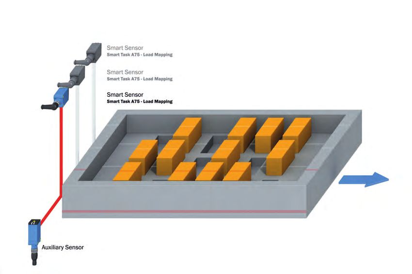
CONTENTS
Contents
1 About this document........................................................................ 4
1.1 Purpose of this document........................................................................ 4
1.2 Intended use............................................................................................. 4
1.3 Symbols..................................................................................................... 4
2 Description of IO-Link....................................................................... 5
3 Accessories for visualization, configuration, and integration..... 6
4 Data repository.................................................................................. 7
5 Physical layer..................................................................................... 8
6 Process data...................................................................................... 9
7 Service data....................................................................................... 11
7.1 Device identification................................................................................. 11
7.2 General device settings............................................................................ 12
7.3 Teach-in/Detection settings for WTB, WTF, WTL and WTS devices....... 15
7.4 Teach-in / detection settings for WL and WLA devices.......................... 18
7.5 Teach-in / detection settings for WLG devices....................................... 21
7.6 Teach-in / detection settings for WE / WEO devices.............................. 26
7.7 Teach-in/Detection settings for WTT devices......................................... 28
7.8 Installation / Diagnostics......................................................................... 32
7.9 Smart Tasks.............................................................................................. 36
7.9.1 Smart Tasks “Basic logic” (A00)............................................. 36
7.9.2 Smart Tasks “Time measurement and debouncing” (A70).. 38
7.9.3 Smart Tasks “Counter and debouncing” (A71)...................... 40
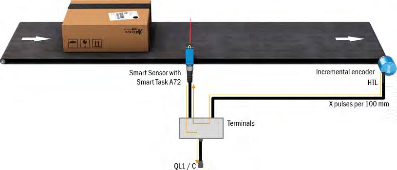
7.9.4 Smart Task “Speed and length measurement” (A72)........... 42
7.9.5 Smart Tasks “Object and gap monitor” (A73)........................ 50
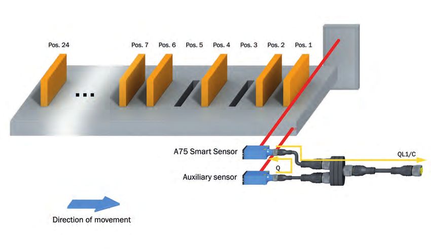
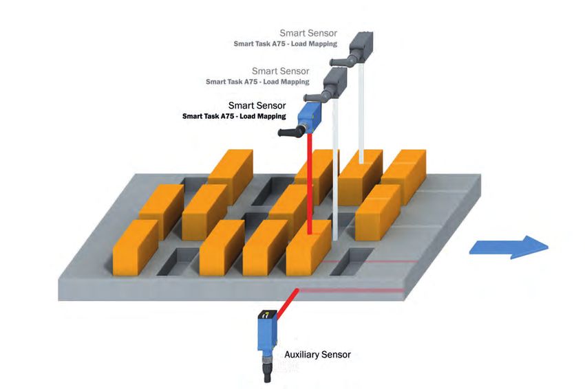
7.9.6 "Load mapping" Smart Task (A75).......................................... 53
7.10 System-specific ISDUs.............................................................................. 63
8 Events.................................................................................................. 65
9 List of abbreviations.......................................................................... 66
10 Index.................................................................................................... 67
8022709.17YN/2020-05-05 | SICK T E C H N I C A L I N F O R M A T I O N | Photoelectric sensors 3
Subject to change without notice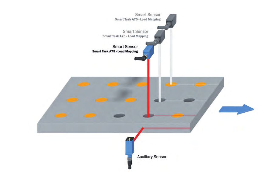
1 ABOUT THIS DOCUMENT

1                About this document
1.1              Purpose of this document
The ISDU descriptions in this document apply to IO-Link-enabled photoelectric sensors (Smart Sensors) with the
following principles of operation:
WTB, WTF, WTL, WTS, WTT, WL, WLA, WLG, WE, WEO.
In some cases, functions may be described in this document which are not supported by individual sensors. The
functions in question are marked accordingly (see "Symbols", page 4).
The specific functional scope of an individual sensor is described in full in the Addendum to operating instructions on
the relevant product page under www.sick.com.

1.2              Intended use
Use IO-Link only as described in this documentation.

1.3              Symbols

NOTICE
This symbol indicates important information.

NOTE
This symbol provides additional information, e.g., dependencies / interactions between the described function and
other functions, or when individual functions are not supported by every sensor.

4        T E C H N I C A L I N F O R M A T I O N | Photoelectric sensors                          8022709.17YN/2020-05-05 | SICK
                                                                                                     Subject to change without notice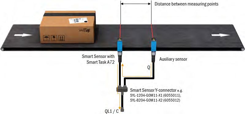
DESCRIPTION OF IO-LINK 2

2                  Description of IO-Link
IO-Link and control integration
IO-Link is a non-proprietary internationally standardized communication technology, which makes it possible to
communicate with sensors and actuators in industrial environments (IEC 61131-9).
IO-Link devices communicate with higher-level control systems via an IO-Link master. The IO-Link devices (slaves)
are connected to these via a point-to-point connection.
Different variants of IO-Link master are available. In most cases, they are remote fieldbus gateways or input cards
for the backplane bus of the control used.
To make it possible for an IO-Link sensor to communicate with the control, both the IO-Link master and the
IO-Link sensor must be integrated in the hardware configuration in the control manufacturer’s Engineering Tool.
To simplify the integration process, SICK provides sensor-specific device description files (IODD = IO-Link Device
Description) for IO-Link devices.
You can download these device description files free of charge: www.sick.com/[device-part number].
Not all control system manufacturers support the use of IODDs. If third-party IO-Link masters are used, it is possi‐
ble to integrate the IO-Link sensor by manually entering the relevant sensor parameters directly during the hard‐
ware configuration.
To ensure that the IO-Link sensor can be easily integrated into the control program, SICK also provides function
blocks for many control systems. These function blocks make it easier to read and write the individual
sensor parameters, for example, and provide support when it comes to interpreting the process data supplied by
the IO-Link sensor. You can also download them free of charge from the homepage: www.sick.com/[device-part
number].
On the SICK YouTube channel, you can find a number of tutorials, which will help you to integrate SICK
IO-Link masters: www.youtube.com/SICKSensors.
If you have any questions, SICK’s Technical Support is available to help all over the world.

8022709.17YN/2020-05-05 | SICK                                          T E C H N I C A L I N F O R M A T I O N | Photoelectric sensors   5
Subject to change without notice
3 ACCESSORIES FOR VISUALIZATION, CONFIGURATION, AND INTEGRATION

3               Accessories for visualization, configuration, and integration
Using the SiLink2-Master, you can easily connect IO-Link sensors from SICK to a PC or a laptop via USB. You can
then quickly and easily test or configure the connected sensors using the SOPAS ET program (SICK Engineering
Tool with graphic user navigation and convenient visualization).

The corresponding visualization files (SDD = SOPAS Device Description) are available for many devices so that you
can operate the IO-Link sensors using SOPAS ET.
You can download SOPAS ET and the device-specific SDDs directly and free of charge from the SICK homepage:
www.sick.com.
Various IO-Link masters are available from SICK for integrating IO-Link masters using fieldbus. For more details,
see: www.sick.com.

6       T E C H N I C A L I N F O R M A T I O N | Photoelectric sensors                       8022709.17YN/2020-05-05 | SICK
                                                                                                 Subject to change without notice
DATA REPOSITORY 4
4 Data repository
When the current IO-Link standard V1.1 was introduced, the automatic data repository (Data Storage) was added
to IO-Link’s range of functions. The data repository allows the machine operator to replace defective IO-Link
devices with corresponding replacement devices without having to reconfigure these manually.
When the data repository is activated, the IO-Link 1.1 master always saves the last valid setting parameters of all
connected IO-Link 1.1 devices in its local memory. If you replace one of the connected IO-Link devices with
another device which is compatible with the function, the IO-Link master will transfer the last valid parameter set
of the previous sensor to the new sensor automatically.
The data repository therefore means that devices can be replaced in a plug-and-play manner within a matter of
seconds – without complex reconfiguration, special hardware or software tools, and specific specialist knowledge.
NOTE
• To use the data repository, you must activate it in the IO-Link master.
• When the conversion of one or several sensor parameters is initiated via the control, then the control must
activate the Data Storage Upload Request-Flag as the final command in the sensor. Only this initiates the data
repository.
• Uploading / downloading sensor parameters using the data repository function can take between a few hun‐
dred milliseconds and three seconds depending on the volume of data and the IO-Link master used (typical
values; values can differ in practice).
• For details on using the data repository, see IO-Link Interface and System Specification, V1.1.2, chapter 10.4
Data Storage (DS) at www.io-link.com, Downloads menu item.
8022709.17YN/2020-05-05 | SICK T E C H N I C A L I N F O R M A T I O N | Photoelectric sensors 7
Subject to change without notice5 PHYSICAL LAYER
5 Physical layer
The physical layer describes the basic IO-Link device data. The device data is automatically shared with the IO-Link
master. It is important to ensure that the used IO-Link master supports this performance data.
NOTICE
The maximum current consumption of the IO-Link sensor (including load at the outputs) must not exceed the per‐
missible output current of the relevant port on the IO-Link master.
The individual IO-Link device data differs from device to device and can be found in the online data sheet of the
respective sensor as well as its addendum to operating instructions:
www.sick.com/[part number] --> Downloads --> Documentation
8 T E C H N I C A L I N F O R M A T I O N | Photoelectric sensors 8022709.17YN/2020-05-05 | SICK
Subject to change without noticePROCESS DATA 6
6 Process data
Process data are transmitted cyclically. There is no confirmation of receipt.
The master determines the cycle time, whereby this must not be less than the minimum cycle time of the sensor.
NOTE
The service data (acyclic data) does not influence the cycle time.
Process data structure for WTBxx, WTFxx, WTLxx, WTSxx, WLAxx, WLGxx, WSExx, each with “Base logic” Smart
Task
Table 1: Process data structure – Basic logic
Byte offset Byte 0 Byte 1
Bit offset 15 14 13 12 11 10 9 8 7 6 5 4 3 2 1 0
Name Reserved QL2 QL1
Data type --- Boolean Boolean
0 = OFF 0 = OFF
Description Reserved
1 = ON 1 = ON
Process data structure for WTBxx, WTFxx, WTLxx, WTSxx, WLAxx, WLGxx, WSExx, each with “Time measurement
and debouncing” Smart Task
Table 2: Process data structure – Time measurement and debouncing
Byte offset Byte 0 Byte 1
Bit offset 15 14 13 12 11 10 9 8 7 6 5 4 3 2 1 0
Name Time measurement value (tmsval) QL2 QL1
Data type Unsigned integer 14 Boolean Boolean
0 = OFF 0 = OFF
Description [ms or 10 ms or 100 ms]
1 = ON 1 = ON
Process data structure for WTBxx, WTFxx, WTLxx, WTSxx, WLAxx, WLGxx, WSExx, each with “Counter and
debouncing” Smart Task
Table 3: Process data structure – Counter and debouncing
Byte offset Byte 0 Byte 1
Bit offset 15 14 13 12 11 10 9 8 7 6 5 4 3 2 1 0
Name Count value (cntval) QL2 QL1
Data type Unsigned integer 14 Boolean Boolean
0 = OFF 0 = OFF
Description ---
1 = ON 1 = ON
Process data structure for WTBxx, WTFxx, WTLxx, WTSxx, WLAxx, WLGxx, WSExx, each with “Speed and length
measurement” Smart Task
Table 4: Process data structure – Speed and length measurement
Byte offset Byte 0 Byte 1
Bit offset 15 14 13 12 11 10 9 8 7 6 5 4 3 2 1 0
Name Measurement value length (lngval) resp. Measurement value speed (spdval) Qint. 1 QL1
Data type Integer 14 Boolean Boolean
0 = OFF 0 = OFF
Description [mm] or [mm/s]
1 = ON 1 = ON
8022709.17YN/2020-05-05 | SICK T E C H N I C A L I N F O R M A T I O N | Photoelectric sensors 9
Subject to change without notice6 PROCESS DATA
Process data structure for WTFxx, WTLxx, WTSxx, WLAxx, WLGxx, WSExx, each with “Object and gap monitor”
Smart Task
Table 5: Process data structure – Object and gap monitor
Byte offset Byte 0 Byte 1
Bit offset 15 14 13 12 11 10 9 8 7 6 5 4 3 2 1 0
Name Time measurement value (tmsval) Qint.1 QL Gap QL Object
Data type Unsigned integer 13 Boolean Boolean Boolean
0 = OFF 0 = OFF 0 = OFF
Description [ms]
1 = ON 1 = ON 1 = ON
NOTE
In order to be able to use the maximum switching frequency for the switching output via pin 2 at the same time as
IO-Link communication, configure pin 2 as Q/or Qint.1. Pin 2/5 configuration (ISDU 121).
Process data structure for WTBxx, WTFxx, WTLxx, WTSxx, WLAxx, WLGxx, WSExx, each with “Load mapping”
Smart Task
Table 6: Process data structure – load mapping
Byte offset Byte 0 Byte 1 Byte 2 Byte 3
Bit offset 63 62 61 60 59 58 57 56 55 54 53 52 51 50 49 48 47 46 45 44 43 42 41 40 38 37 36 35 34 33 32
Name Load Mapping positions occupied
Data type Unsigned integer 32
Description Bit mask: Bit = 1 --> Object present; Bit = 0 --> No object present; Bit 32-55 in use for load mapping, Bit 56-63 is not in use
Table 7: Process data structure – load mapping
Byte off‐
Byte 4 Byte 5 Byte 6 Byte 7
set
Bit offset 31 30 29 28 27 26 25 24 23 22 21 20 19 18 17 16 15 14 13 12 11 10 9 8 7 6 5 4 3 2 1 0
Invalid
pat‐
Name Number of objects in last pattern seen Reserved Status tern Reserved Qint.1 QL1
clip‐
ping
Boolea
Data type Unsigned integer 8 - Uint 4 - Boolean
n
0= 0= 0=
Descrip‐
Reserved - OFF Reserved OFF OFF
tion
1 = ON 1 = ON 1 = ON
Process data structure for WTT with or without "Base logic” Smart Task
Table 8: Process data structure – WTTxx with or without "Base logic" Smart Task
Byte off‐
Byte 0 Byte 1 Byte 2 Byte 3
set
Bit off‐
31 30 29 28 27 26 25 24 23 22 21 20 19 18 17 16 15 14 13 12 11 10 9 8 7 6 5 4 3 2 1 0
set
Qint Qint Qint Qint Qint Qint Qint Qint QL QL
Name Distance to object Reserved
.8 .7 .6 .5 .4 .3 .2 .1 2 1
Data
Unsigned integer 16 - Boolean
type
Descrip‐ 0 = OFF
[mm] Reserved
tion 1 = ON
10 T E C H N I C A L I N F O R M A T I O N | Photoelectric sensors 8022709.17YN/2020-05-05 | SICK
Subject to change without noticeSERVICE DATA 7
7 Service data
Service data is only exchanged between the control and IO-Link sensor via the IO-Link master on request by the
control (acyclically).
The respective counterpart confirms receipt of the data.
If the sensor does not answer within five seconds, the master reports a communication error.
NOTE
Not every function described in this document is available in every sensor. The complete list of the parameters
available in the individual devices can be found in the “Addendum to operating instructions” document, which is
found on the web page of the respective device: www.sick.com/[part number] --> Downloads --> Documents.
7.1 Device identification
Table 9: Device identification
ISDU
Data stor‐ Default
Index Sub- Name Data type Length Access Value/Range
age value
DEC HEX index
16 10 Vendor name 7 byte SICK AG
18 12 Product name 18 byte
- String
see ISDU
19 13 Product ID - 13 byte ro
219
0 Product ID Record 7 byte
219 DB
1 Product ID IO-Link device String 7 byte
The Product ID also contains the part number of the connected IO-Link device. For reasons of standardization, this
may also contain a reference to ISDU 219. In this case, the Product ID (part number) is filed under ISDU 219.
Table 10: Device identification – Product text/serial number
ISDU
Data Stor‐ Default
Index Sub- Name Data type Length Access Value/range
age value
DEC HEX index
20 14 - Product text 45 bytes
String - ro
21 15 - Serial Number 8 bytes
Serial number format:
YYWWnnnn (Y = year, W = week, n = sequential numbering)
NOTE
The serial number combined with the part number (Product ID) enables the device to be clearly identified.
Table 11: Device identification – Specific tag / specific name
ISDU
Data Stor‐
Index Sub- Name Data type Length Access Default value Value/range
age
DEC HEX index
24 18 - Application-specific tag yes *******
String 32 bytes rw
64 40 - Device-specific name No *******
In Application Specific Tag, you can store any text with a maximum of 32 characters. This can be useful for describing
the exact position or task of the sensor in the overall machine. The Application Specific Tag is saved via the Data
repository.
In Device Specific Name, you can also store any text with a maximum of 32 characters. This name is NOT saved via
the Data repository and is therefore available for information which is valid temporarily or for information which is
only applicable to this sensor.
8022709.17YN/2020-05-05 | SICK T E C H N I C A L I N F O R M A T I O N | Photoelectric sensors 11
Subject to change without notice7 SERVICE DATA
Table 12: Device identification – Version
ISDU
Data reposi‐ Default
Index Sub- Name Data type Length Access Value/range
tory value
DEC HEX index
22 16 - Hardware version 4 byte xxxx
String yes ro
23 17 - Firmware version 12 byte Vxxx.xxx.xxx
This ISDU indicates the hardware and software versions.
Table 13: Device identification – Find me
ISDU
Data reposi‐ Default
Index Sub- Name Data type Length Access Value/range
tory value
DEC HEX index
0 = Find me deactivated
204 CC - Find me UInt No 8 bit rw 0
1 = Find me activated
The sensor can be uniquely identified using Find me. For machines with several identical sensors, it is therefore
possible to uniquely identify the device with which communication is currently taking place.
When Find me is activated, the yellow indicator LED of the sensor flashes at 1 Hz.
7.2 General device settings
Table 14: General device settings – Standard command
ISDU
Data stor‐ Default
Index Sub- Name Data type Length Access Value/Range
age value
DEC HEX index
2 02 - Standard command UInt - 1 Byte wo 130 = Restore Factory Settings
Restore Factory Settings: The sensor is reset to factory settings.
Table 15: General device settings – Device access locks
ISDU
Data reposi‐ Default
Index Sub- Name Data type Length Access Value/range
tory value
DEC HEX index
Device access locks (key Bit no.
lock) 0
0 = Unlocked
Data storage lock 0 1
1 = Locked
12 02 - Record yes 2 byte rw
Not available 2 Not available
0 = Unlocked
Local user interface lock 0 3
1 = Locked
Not available 4 – 15 Not available
With Device access locks, you can lock or unlock various sensor functions. The functionality has been recorded in the
IO-Link interface specification.
Bit 1 Data storage lock You can lock the data repository functionality using bit 1. When the bit is set, the sensor
rejects data repository write requests from the IO-Link master with an error message.
For newer devices, the data repository function can no longer be deactivated.
Bit 3 Local user The local control elements on the sensor are locked when the bit is set.
interface lock The lock can be disabled for 30 seconds: Press the teach-in button for 8 seconds. The
control elements are then locked again automatically once 30 seconds have passed.
Local user interface lock is not available when the sensor does not have any housing con‐
trol elements.
12 T E C H N I C A L I N F O R M A T I O N | Photoelectric sensors 8022709.17YN/2020-05-05 | SICK
Subject to change without noticeSERVICE DATA 7
Table 16: General device settings – Physical input/output type configuration pin 2
ISDU
Data stor‐ Default
Index Sub- Name Data type Length Access Value/Range
age value
DEC HEX index
1 = PNP
Physical input/output type
92 5C - UInt yes 1 byte rw 3 2 = NPN
configuration pin 2
3 = Push/Pull
Physical input/output type configuration pin 2 makes it possible to determine the wiring on pin 2. If the device is used in
an NPN network and pin 2 should be used as an input function, this parameter must be set to 2 = NPN in
advance.
NOTE
Dependency: Pin 2 configuration (ISDU 121)
Table 17: General device settings – Sender configuration
ISDU
Data reposi‐ Default
Index Sub- Name Data type Length Access Value/range
tory value
DEC HEX index
0 = Sender active
97 61 - Sender configuration UInt - 1 byte rw 0
1 = Sender not active
This ISDU can be used to switch off the Send LED.
Alternatively, the sensor’s Send LED can be deactivated using the HIGH signal on pin 2 (when Pin 2 configuration
(ISDU 121) is Sender off).
If the settings contradict one another, the Switch-off signal is dominant.
If the sensor does not have a Send LED (e.g., the WExx): Sender configuration is not available.
NOTE
Dependency: Pin 2 configuration Sender off (ISDU 121)
Table 18: General device settings - Process data select
ISDU
Data stor‐ Default
Index Sub- Name Data type Length Access Value/Range
age value
Dec Hex index
0 = device specific
1 = device specific
120 78 - Process data select UInt yes 1 byte rw 0 2 = device specific
3=…
…
Process data select can be used to determine which process data structure of the sensor is to be output cyclically.
The possible process data structures are fixed. See the respective device documentation for details on the process
data structures.
Table 19: General device settings – Pin 2 configuration
ISDU
Data stor‐ Default
Index Sub- Name Data type Length Access Value/Range
age value
DEC HEX index
0 = Deactivated/no function
Inputs:
1 = External input (Smart Task)
16 = Sender off
17 = Teach-in
Outputs:
32 = Detection output Q/
121 79 - Pin2 configuration UInt yes 1 byte rw 32 resp. 40
33 = Quality of run alarm output
34 = Switching signal QL2
35 = Detection output Qint.1
36 = Detection output Qint.2
39 = Switching signal QL1
40 = Switching signal QL1/
43 = Health output
8022709.17YN/2020-05-05 | SICK T E C H N I C A L I N F O R M A T I O N | Photoelectric sensors 13
Subject to change without notice7 SERVICE DATA
Pin 2 configuration can be used to assign a range of input and output functions to pin 2 in the device connector (or
the white wire when using a connecting cable).
Deactivated The signal level at pin 2 is not evaluated.
External input (Smart Task) Input signal; is processed in Smart Task (if present).
Sender off Input signal;
Level at pin 2 HIGH 1): Sender LED of the sensor switched off
Level at pin 2 LOW 2): Sender LED of the sensor switched on (if this is not deacti‐
vated via the Sender configuration (ISDU 97).
Does not apply for WExx devices.
Teach-in Input signal;
Level at pin 2 HIGH for at least 1 second 1): Triggers the teach command.
For WTBxx, WTFxx, WTLxx, WTSxx, WTTxx; the current distance between the sen‐
sor and the object in the light beam is set as the sensing range, if necessary
corrected by the set Teach-in offset value (ISDU 90).
For WLxx, WLGxx, WLAxx and, if necessary, WExx; the sensor’s sensitivity is
adjusted to the current energetic situation.
Detection output Q/ Output signal; signal level device specific
WTBxx, WTFxx, WTLxx, WTSxx: LOW2) if the detection object is detected by the
sensor. WLxx, WLGxx, WLAxx, WExx: HIGH1) if the detection object is detected by
the sensor.
Quality of run alarm output Output signal; HIGH1) if the Quality of run value (ISDU 175) undercuts the set
alarm threshold (Quality of run alarm threshold, ISDU 176).
Switching signal QL2 Output signal; switching signal generated from Smart Task.
Detection output Qint.1 Output signal; HIGH1) when detection object is detected by sensor via Qint.1
channel.
Detection output Qint.2 Output signal; HIGH1) when detection object is detected by sensor via Qint.2
channel.
Switching signal QL1 Output signal; switching signal generated from Smart Task.
Switching signal QL1/ Output signal; inverted signal to QL1.
Health output Output signal; inverted signal to Quality of run alarm output.
1) HIGH = Signal level to L+
2) LOW = Signal level at ground or pin/wire not connected
NOTE
Not every device supports each individual pin 2 function. See IODD of the respective device for more information.
Table 20: General device settings – Notification handling
ISDU
Data stor‐ Default
Index Sub- Name Data type Length Access Value/Range
age value
DEC HEX index
0 = All enabled
1 = All disabled
227 E3 - Notification handling UInt - 1 byte rw 0
2 = Events enabled, PD invalid flag disabled
3 = Events disabled, PD invalid flag enabled
Notification handling enables the generation of IO-Link events in the sensor and the function for marking the process
data as invalid to be activated/deactivated.
Table 21: Installation/Diagnostics – Eco mode
ISDU
Data stor‐ Default
Index Sub- Name Data type Length Access Value/Range
age value
DEC HEX index
0 = Off
235 IB 0 Eco mode UInt - 3 byte ro 0
1 = On
When activating eco mode, the display is deactivated 20 s after the last entry.
14 T E C H N I C A L I N F O R M A T I O N | Photoelectric sensors 8022709.17YN/2020-05-05 | SICK
Subject to change without noticeSERVICE DATA 7
Table 22: General device settings – Inverter external input
ISDU
Data stor‐ Default
Index Sub- Name Data type Length Access Value/Range
age value
Dec Hex index
0 = Not inverted
1093 445 - Inverter external input UInt yes 1 byte rw 0
1 = Inverted
If the Inverter external input is activated, all binary input signals read via pin 2 are inverted before device-internal
processing. Teach-in input signals are exceptions. These are always processed non-inverted regardless of the
Inverter external input setting.
NOTE
Depending on the device generation, the Inverter external input only functions for Smart Task input signals and there‐
fore depending on the setting under ISDU 121 Pin 2 configuration.
7.3 Teach-in/Detection settings for WTB, WTF, WTL and WTS devices
Table 23: Teach-in/Detection – Standard command
ISDU
Data stor‐ Default
Index Sub- Name Data type Length Access Value/Range
age value
DEC HEX index
2 2 - Standard command UInt - 1 byte wo - 65 = Single value teach
After the teach-in command has been triggered, the current distance between the sensor and the object in the
light beam is set as the sensing range. Qint.1 SP1 sensing range (ISDU 60) and Qint.2 SP1 sensing range (ISDU 62)
change accordingly.
NOTE
The same effect is achieved by:
• Triggering teach-in using the teach-in button on the sensor housing (if present).
• Triggering teach-in using the HIGH signal (L+) on pin 2 (when Pin 2 configuration (ISDU 121)) is set to Teach-in).
NOTE
Dependency:
• Teach-in channel (ISDU 58)
• Qint.1 SP1 sensing range (ISDU 60)
• Qint.2 SP1 sensing range (ISDU 62)
• Quality of Teach (ISDU 114)
Table 24: Teach-in/Detection – Teach-in channel/Teach state
ISDU
Data stor‐ Default
Index Sub- Name Data type Length Access Value/Range
age value
DEC HEX index
58 3A - Teach-in channel UInt - 1 byte rw 0 0 to 2 = Default BDC
Teach-in state Record 1 byte
1 bit 0 = Teachpoint 1 not taught
Teach flags
(offset 4 bit) 1 = Teachpoint 1 successfully taught
59 3B - - ro -
0 = IDLE
4 bit 1 = SP1 SUCCESS
Teach state
(offset 0 bit) 5 = BUSY
7 = ERROR
Selection of the Qint. channel that is affected by the Single value teach (ISDU 2, value 65) system command.
Only one teach-in channel is available for the teach-in process for WTB, WTS and WTL devices. Only the preset
teach-in channel can be used.
The Teach state shows the current status of the teach-in process.
A teach-in process can only be performed when the status is IDLE, SP1 SUCCESS and ERROR.
8022709.17YN/2020-05-05 | SICK T E C H N I C A L I N F O R M A T I O N | Photoelectric sensors 15
Subject to change without notice7 SERVICE DATA
The status always refers to the Qint. channel selected in Teach-in channel (ISDU 58). The Teach flags have no function
for WTB, WTS, and WTL devices.
Table 25: Teach-in / detection – Qint.1
ISDU
Data reposi‐ Default
Index Sub- Name Data type Length Access Value/range
tory value
DEC HEX index
0 Qint.1 SP1 / SP2 Record 3 byte -
Device spe‐
60 3C 1 Qint.1 SP1 sensing range yes 16 bit rw 0 to 65535
cific
2 Qint.1 SP2 sensing range 8 bit - Not used
0 Qint.1 configuration Record 4 byte -
8 bit
1 Qint.1 Switchpoint logic 128 128 = Vendor specific
(Offset 24 bit)
61 3D yes 8 bit rw
2 Qint.1 Switchpoint mode 128 128 = Vendor specific
(Offset 16 bit)
Qint.1 Switchpoint hystere‐ 16 bit
3 0 0 = Auto-defined hysteresis
sis (Offset 0 bit)
Qint.1 SP1 sensing range can be used to adjust the sensor’s sensing range (in mm).
The value range is restricted by the sensor’s “max. sensing range” (see sensor data sheet for “max. sensing
range”).
If the current distance between sensor and detection object is the same or less than the set Qint.1 SP1 sensing range
value, the Qint.1 detection signal switches to HIGH.
The selected sensing range can be overwritten by:
• Triggering teach-in using the teach-in button on the sensor housing.
• Triggering teach-in using the HIGH signal (L+) on pin 2 (when Pin 2 configuration (ISDU 121) is set to Teach-in).
Qint.1 SP2 sensing range has no function.
Depending on the device, Qint.1 SP1 / SP2 (ISDU 60) and Qint.2 SP1 / SP2 (ISDU 62) are synchronized.
Any changes made to one of the ISDUs are automatically accepted by the other ISDU.
NOTE
Dependency:
• System command Single value teach (ISDU 2, value 65).
• Qint.2 SP1 sensing range (ISDU 62).
Qint.1 Switchpoint logic has no function.
Qint.1 Switchpoint mode has no function.
Qint.1 Switchpoint hysteresishas no function.
Table 26: Teach-in / detection – Qint.2
ISDU
Data reposi‐ Default
Index Sub- Name Data type Length Access Value/range
tory value
DEC HEX index
0 Qint.2 SP1 / SP2 Record 3 byte -
Device spe‐
62 3E 1 Qint.2 SP1 sensing range yes 16 bit rw 0 to 65535
cific
2 Qint.2 SP2 sensing range 8 bit - Not used
0 Qint.2 configuration Record 4 byte -
8 bit
1 Qint.2 Switchpoint logic 128 128 = Vendor specific
(Offset 24 bit)
63 3F yes 8 bit rw
2 Qint.2 switchpoint mode 128 128 = Vendor specific
(Offset 16 bit)
Qint.2 switchpoint hystere‐ 16 bit
3 0 0 = Auto-defined hysteresis
sis (Offset 0 bit)
Qint.2 SP1 sensing range can be used to adjust the sensor’s sensing range (in mm).
16 T E C H N I C A L I N F O R M A T I O N | Photoelectric sensors 8022709.17YN/2020-05-05 | SICK
Subject to change without noticeSERVICE DATA 7
The value range is restricted by the sensor’s “max. sensing range” (see sensor data sheet for “max. sensing
range”).
If the current distance between sensor and detection object is the same or less than the set Qint.2 SP1 sensing range
value, the Qint.2 detection signal switches to HIGH.
The selected sensing range can be overwritten by:
• Triggering teach-in using the teach-in button on the sensor housing.
• Triggering the teach-in via HIGH1) signal at pin 2 (if pin 2 configuration (ISDU 121) is set to Teach-in).
Qint.2 SP2 sensing range has no function.
Depending on the device, Qint.1 SP1 / SP2 (ISDU 60) and Qint.2 SP1 / SP2 (ISDU 62) are synchronized. Any changes
made to one of the ISDUs are automatically accepted by the other ISDU.
NOTE
Dependency:
• System command Single value teach (ISDU 2, value 65).
• Qint.1 SP1 sensing range (ISDU 60)
Qint.2 Switchpoint logic has no function.
Qint.2 Switchpoint mode has no function.
Qint.2 Switchpoint hysteresis has no function.
Table 27: Teach-in/Detection - Detection mode
ISDU
Data stor‐ Default
Index Sub- Name Data type Length Access Value/Range
age value
DEC HEX index
0 = Switching mode
83 53 - Detection mode UInt yes 1 byte rw 0
1 = Distance measuring mode
Photoelectric proximity sensors which can not only detect binary detection signals, but also the distance to the
object, feature the Detection mode function. Depending on the setting, the photoelectric proximity sensor is in
switching or measuring mode.
The setting of Detection mode also affects Process data select (ISDU120):
• In the 0 = Switching mode setting, Process data select is automatically set to 0 = Switching signals.
• In the 1 = Distance measuring mode setting, Process data select is automatically set to 1 = Distance to object.
NOTE
Dependency:
Process data select (ISDU 120)
Table 28: Teach-in/Detection – Teach-in offset
ISDU Data Defa
Index Sub- Data repo Acce ult
Name Length Value/Range
inde type sitor ss valu
Dec Hex x y e
-100 … +100
90 5A - Teach-in offset Int yes 1 byte rw 0 Alternatively:
-50 … +50
When this function is in use, when triggering a teach-in command (via the teach-in button on the sensor housing or
via the Single value teach system command (ISDU 2, value 65)), the defined detection point is corrected by the set
value.
This function makes it possible to increase detection reliability, especially for teach-in ongoing processes, by mov‐
ing the detection point with the Teach-in offset e.g. “into the object”.
1) HIGH = signal level at L+
8022709.17YN/2020-05-05 | SICK T E C H N I C A L I N F O R M A T I O N | Photoelectric sensors 17
Subject to change without notice7 SERVICE DATA
NOTE
Dependency:
Single value teach system command (ISDU 2, value 65)
NOTE
The Teach-in offset does not work if a sensing range is set directly via Qint.x SP1/SP2 (ISDU 60/62).
Table 29: Teach-in/Detection – Current receiver level
ISDU
Data stor‐ Default
Index Sub- Name Data type Length Access Value/Range
age value
DEC HEX index
180 B4 - Current receiver level (live) UInt - 1 byte ro - 0 ... 16383
Current receiver level (live) shows the sensor’s current energy-related receiver level as an absolute value in digits. This
value therefore delivers additional information about the object on which the sensor light spot falls at the time of
read out.
The displayed value is not affected by the teach-in or from other sensor settings. It also does not directly affect the
detection behavior of the sensor. The value is not calibrated and can fluctuate from sensor to sensor.
Table 30: Teach-in/Detection - Distance to object
ISDU
Data stor‐ Default
Index Sub- Name Data type Length Access Value/Range
age value
DEC HEX index
0 Distance to object Record 3 byte
16 bit
1 Distance UInt 0 … 30000
229 E5 - (offset 8) ro -
2 bit 0 = Distance in range/valid
2 Distance qualifier UInt
(offset 0) 3 = No distance information/distance invalid
This parameter can be used to output the measured distance to the object or the background (if available and in
sensing range) as a Distance in mm or 1/10 mm (depending on the device – see IODD of the respective device for
details). If no measured value can be detected (e.g. because the sensor is facing empty space) or if the measured
value is outside of the specified sensing range, the sensor delivers output value “30,000”, which is to be inter‐
preted as an invalid measurement.
Each measured value must be linked with the Distance qualifier. This value specifies whether the current output
measured value is valid or not.
NOTE
Separate access to sub-index 1 or 2 is not possible.
7.4 Teach-in / detection settings for WL and WLA devices
Table 31: Teach-in/Detection – Standard command
ISDU
Data stor‐ Default
Index Sub- Name Data type Length Access Value/Range
age value
DEC HEX index
2 2 - Standard command UInt - 1 byte wo - 65 = Single value teach
For WL devices, we recommend performing a teach-in process after connecting the sensor and aligning it to the
reflector. This automatically adjusts the sensor’s receiver sensitivity, taking into account the current light receiver
level, so that the detection signal is as reliable as possible.
For WLA devices, a teach-in process is not required for detector-related reasons, as these systems guarantee reli‐
able and robust object detection even at maximum sensitivity (= delivery status).
To be able to use all of the following functions/parameters to their full extent, a teach-in process must be trig‐
gered:
18 T E C H N I C A L I N F O R M A T I O N | Photoelectric sensors 8022709.17YN/2020-05-05 | SICK
Subject to change without noticeSERVICE DATA 7
• Qint.1 SP1 / SP2 (ISDU 60) or Qint.2 SP1 / SP2 (ISDU 62)
• Quality of run (ISDU 175)
• Quality of run alarm (ISDU 176)
• Current receiver level (ISDU 180)
With every teach-in process, the sensor’s current light receiver level, Current receiver level (live) (ISDU 180), is stan‐
dardized at 100%. These 100% levels are the energy-based reference values for the aforementioned functions and
parameters. If the teach-in process is not performed, the reference value is undefined and the listed functions and
parameters do not deliver any valid information.
To achieve the same effect as the “Single value teach” standard command, you can trigger teach-in using the
teach-in pushbutton on the sensor housing (if present) or trigger teach-in via the HIGH signal (L+) at pin 2 (when
Pin 2 configuration (ISDU 121) is set to Teach-in).
NOTE
Dependency:
• Qint.1 SP1 / SP2 (ISDU 60)
• Qint.2 SP1 / SP2 (ISDU 62)
• Quality of run (ISDU 175)
• Quality of run alarm (ISDU 176)
• Current receiver level (live) (ISDU 180)
Table 32: Teach-in/Detection – Teach-in channel/Teach state
ISDU
Data stor‐ Default
Index Sub- Name Data type Length Access Value/Range
age value
DEC HEX index
58 3A - Teach-in channel UInt - 1 byte rw 0 0 to 2 = Default BDC
Teach-in state Record 1 byte
1 bit 0 = Teachpoint 1 not taught
Teach flags
(offset 4 bit) 1 = Teachpoint 1 successfully taught
59 3B - - ro -
0 = IDLE
4 bit 1 = SP1 SUCCESS
Teach state
(offset 0 bit) 5 = BUSY
7 = ERROR
Selection of the Qint. channel that is affected by the Single value teach (ISDU 2, value 65) system command.
Only one teach-in channel is available for the teach-in process for WL and WLA devices. Only the preset teach-in
channel can be used.
The Teach state shows the current status of the teach-in process.
A teach-in process can only be performed when the status is IDLE, SP1 SUCCESS and ERROR.
The status always refers to the Qint. channel selected in Teach-in channel (ISDU 58).
The Teach flags have no function for WL and WLA devices.
Table 33: Teach-in / detection – Qint.1
ISDU
Data reposi‐ Default
Index Sub- Name Data type Length Access Value/range
tory value
DEC HEX index
0 Qint.1 SP1 / SP2 Record 2 byte -
SP1 upper threshold (switch- 8 bit
1 50 50
60 3C on) (Offset 8 bit)
SP2 lower threshold (switch- 8 bit
2 45 45
off) (Offset 0 bit)
0 Qint.1 configuration Record 4 byte -
yes rw
8 bit
1 Switchpoint logic
(Offset 24 bit)
128 128 = Vendor specific
61 3D 8 bit
2 Switchpoint mode
(Offset 16 bit)
16 bit
3 Switchpoint hysteresis 0 0 = Auto-defined hysteresis
(Offset 0 bit)
8022709.17YN/2020-05-05 | SICK T E C H N I C A L I N F O R M A T I O N | Photoelectric sensors 19
Subject to change without notice7 SERVICE DATA
Qint.1 SP1 / SP2 is used to defined the switch-on and switch-off threshold for the detection signal (as percentages).
The selected values are based on the energy-based receiver value (=100%) defined during the last teach-in
process.
SP1 upper threshold (switch-on): Switch-on threshold.
If the Current receiver level (live) (ISDU 180) exceeds the selected switch-on threshold, the Qint.1 detection signal
changes to LOW (no object detected in beam path).
SP2 lower threshold (switch-off): Switch-off threshold.
If the Current receiver level (live) (ISDU 180) falls below the set switch-off threshold, the Qint.1 detection signal
switches to HIGH (object detected in beam path).
NOTE
The default switch-on and switch-off thresholds cannot be adjusted in WL / WLA devices. This is only possible in
WLG devices (see "Teach-in / detection settings for WLG devices", page 21). The settings and their effects are
redundant to those in ISDU 62.
NOTE
Dependency:
• Qint.2 SP1 / SP2 (ISDU 62)
• Current receiver level (live) (ISDU 180)
Switchpoint logic has no function.
Switchpoint mode has no function.
Switchpoint hysteresis has no function.
Table 34: Teach-in / detection – Qint.2
ISDU
Data reposi‐ Default
Index Sub- Name Data type Length Access Value/range
tory value
DEC HEX index
0 Qint.2 SP1 / SP2 Record 2 byte -
SP1 upper threshold 8 bit
1 50 50
62 3E (switch-on) (Offset 8 bit)
SP2 lower threshold (switch- 8 bit
2 45 45
off) (Offset 0 bit)
0 Qint.2 configuration Record 4 byte -
yes rw
8 bit
1 Switchpoint logic
(Offset 24 bit)
128 128 = Vendor specific
63 3F 8 bit
2 Switchpoint mode
(Offset 16 bit)
16 bit
3 Switchpoint hysteresis 0 0 = Auto-defined hysteresis
(Offset 0 bit)
Qint.2 SP1 / SP2 is used to defined the switch-on and switch-off threshold for the detection signal (as percentages).
The selected values are based on the energy-based receiver value (=100%) defined during the last teach-in
process.
SP1 upper threshold (switch-on): Switch-on threshold.
If the Current receiver level (live) (ISDU 180) exceeds the selected switch-on threshold, the Qint.1 detection signal
changes to LOW (no object detected in beam path).
SP2 lower threshold (switch-off): Switch-off threshold.
If the Current receiver level (live) (ISDU 180) falls below the selected switch-off threshold, the Qint.1 detection signal
changes to HIGH (object detected in beam path).
NOTE
The default switch-on and switch-off thresholds cannot be adjusted in WL / WLA devices. This is only possible in
WLG devices (see "Teach-in / detection settings for WLG devices", page 21). The settings and their effects are
redundant to those in ISDU 60.
20 T E C H N I C A L I N F O R M A T I O N | Photoelectric sensors 8022709.17YN/2020-05-05 | SICK
Subject to change without noticeSERVICE DATA 7
NOTE
Dependency:
• Qint.1 SP1 / SP2 (ISDU 60)
• Current receiver level (live) (ISDU 180)
Switchpoint logic has no function.
Switchpoint mode has no function.
Switchpoint hysteresis has no function.
Table 35: Teach-in / detection – Current receiver level
ISDU
Data reposi‐ Default
Index Sub- Name Data type Length Access Value/range
tory value
DEC HEX index
180 B4 - Current receiver level (live) UInt - 1 byte ro - 0 to 255
Current receiver level (live) shows the sensor’s current energy-related receiver level (as a percentage). The reference
point (equivalent to 100%) is the Current receiver level (live) at the time of the last teach-in.
For further details, see the Single value teach standard command (ISDU 2, value 65).
NOTE
Dependency:
• System command Single value teach (ISDU 2, value 65)
7.5 Teach-in / detection settings for WLG devices
Table 36: Teach-in/Detection – Standard command
ISDU
Data stor‐ Default
Index Sub- Name Data type Length Access Value/Range
age value
DEC HEX index
2 2 - Standard command UInt - 1 byte wo - 65 = Single value teach
For WLG devices, a teach-in process must be performed after connecting the sensor and aligning it to the reflector.
This automatically adjusts the sensor’s receiver sensitivity, taking into account the current light receiver level, so
that the detection signal is as reliable as possible, even for highly transparent objects.
In addition, with every teach-in, the current light receiver level of the sensor, the Current receiver level (live) (ISDU
180), is standardized at 100%. These 100% levels are the energy-based reference values for the following device
functions:
• Qint.1 SP1 / SP2 (ISDU 60) or Qint.2 SP1 / SP2 (ISDU 62)
• Quality of teach (ISDU 114)
• Quality of run (ISDU 175)
• Upper threshold (switch-on) dynamic (ISDU 181); effective detector-related switch-on and switch-off thresholds
• Lower threshold (switch-off) dynamic (ISDU 182); effective detector-related switch-on and switch-off thresholds
The teach-in process must be repeated each time the sensor or reflector is realigned or whenever the sensor or
reflector is replaced in order to guarantee that the energy-related reference signal is always up-to-date, e.g., for
assessing contamination on the sensor’s front screen or the reflector. This also applies to the use of the data
repository function (see "Data repository", page 7).
If the teach-in process is not performed, the reference value is undefined and the listed functions and parameters
do not deliver any valid information.
The Single value teach standard command has the same effect:
• Triggering teach-in using the teach pushbutton on the sensor housing (if present).
• Triggering teach-in using the HIGH signal (L+) on pin 2 (when Pin 2 configuration (ISDU 12) is set to Teach-in).
8022709.17YN/2020-05-05 | SICK T E C H N I C A L I N F O R M A T I O N | Photoelectric sensors 21
Subject to change without notice7 SERVICE DATA
NOTE
Dependency:
• Qint.1 SP1 / SP2 (ISDU 60)
• Qint.2 SP1 / SP2 (ISDU 62)
• Quality of run (ISDU 175)
• Quality of run alarm (ISDU 176)
• Current receiver level (live) (ISDU 180)
• Upper threshold (switch-on) dynamic (ISDU 181)
• Lower threshold (switch-off) dynamic (ISDU 182)
Table 37: Teach-in/Detection – Teach-in channel/Teach state
ISDU
Data stor‐ Default
Index Sub- Name Data type Length Access Value/Range
age value
DEC HEX index
58 3A - Teach-in channel UInt - 1 byte rw 0 0 to 2 = Default BDC
Teach-in state Record 1 byte
1 bit 0 = Teachpoint 1 not taught
Teach flags
(offset 4 bit) 1 = Teachpoint 1 successfully taught
59 3B - - ro -
0 = IDLE
4 bit 1 = SP1 SUCCESS
Teach state
(offset 0 bit) 5 = BUSY
7 = ERROR
Selection of the Qint. channel that is affected by the Single value teach (ISDU 2, value 65) system command.
Only one teach-in channel is available for the teach-in process for WLG devices. Only the preset teach-in channel
can be used.
The Teach state shows the current status of the teach-in process. A teach-in process can only be performed when
the status is IDLE, SP1 SUCCESS, and ERROR.
The status always refers to the Qint. channel currently selected via the Teach-in channel (ISDU 58).
The Teach flags do not have a function for WLG devices.
Table 38: Teach-in / detection – Qint.1
ISDU
Data reposi‐ Default
Index Sub- Name Data type Length Access Value/range
tory value
DEC HEX index
0 Qint.1 SP1 / SP2 Record 2 byte -
SP1 upper threshold 8 bit 10 to 90
1 90
60 3C (switch-on) (Offset 8 bit) 110 to 200
SP2 lower threshold (switch- 8 bit 5 to 85
2 85
off) (Offset 0 bit) 105 to 195
0 Qint.1 configuration Record yes 4 byte rw -
8 bit
1 Switchpoint logic
(Offset 24 bit)
128 128 = Vendor specific
61 3D 8 bit
2 Switchpoint mode
(Offset 16 bit)
16 bit
3 Switchpoint hysteresis 0 0 = Auto-defined hysteresis
(Offset 0 bit)
22 T E C H N I C A L I N F O R M A T I O N | Photoelectric sensors 8022709.17YN/2020-05-05 | SICK
Subject to change without noticeSERVICE DATA 7
Table 39: Teach-in / detection – Qint.2
ISDU
Data reposi‐ Default
Index Sub- Name Data type Length Access Value/range
tory value
DEC HEX index
0 Qint.2 SP1 / SP2 Record 2 byte -
SP1 upper threshold 8 bits 10 to 90
1 90
62 3E (switch-on) (Offset 8 bit) 110 to 200
SP2 lower threshold (switch- 8 bit 5 to 85
2 85
off) (Offset 0 bit) 105 to 195
0 Qint.2 configuration Record yes 4 byte rw -
8 bit
1 Switchpoint logic
(Offset 24 bit)
128 128 = Vendor specific
63 3F 8 bit
2 Switchpoint mode
(Offset 16 bit)
16 bit
3 Switchpoint hysteresis 0 0 = Auto-defined hysteresis
(Offset 0 bit)
Qint.1 / Qint.2 SP1 / SP2 is used to define the switch-on and switch-off threshold for the detection signal (as percent‐
ages). The selected values are based on the energy-based receiver value (=100%) defined during the last teach-in
process.
SP1 upper threshold (switch-on): Switch-on threshold.
If the Current receiver level (live) (ISDU 180) exceeds the selected switch-on threshold or the dynamic switch-on
threshold (see AutoAdapt, ISDU 112), the Qint.1 detection signal changes to LOW (no object detected in beam path).
SP2 lower threshold (switch-off): Switch-off threshold.
If the Current receiver level (live) (ISDU 180) falls below the selected switch-off threshold or the dynamic switch-off
threshold (see AutoAdapt, ISDU 112), the Qint.1 detection signal changes to HIGH (object detected in beam path).
The switch-on threshold must always be higher than the switch-off threshold.
The minimum distance between the switch-on and switch-off threshold is 5% (= hysteresis).
Both switching thresholds must always be both below 100% or above 100%.
Depending on the mode selected under Detection mode (ISDU 83), the switch-on and switch-off thresholds are auto‐
matically adjusted.
Qint.1 SP1 / SP2 (ISDU 60) and Qint.2 SP1 / SP2 (ISDU 62) are always synchronous.
Any changes made to one of the ISDUs are accepted by the other ISDU.
NOTE
Dependency:
• Qint.1 SP1 / SP2 (ISDU 60)
• Qint.2 SP1 / SP2 (ISDU 62)
• Current receiver level (live) (ISDU 180)
Switchpoint logic has no function.
Switchpoint mode has no function.
Switchpoint hysteresis has no function.
Table 40: Teach-in / detection – Detection mode
ISDU
Data reposi‐ Default
Index Sub- Name Data type Length Access Value/range
tory value
DEC HEX index
Value / Range set 1:
0 = Highly-transparent objects
1 = Semi-transparent objects
2 = Opaque objects
3 = Bottles / trays
4 = Foil tear
83 53 - Detection mode UInt yes 1 byte rw 0
255 = Manual
Value / Range set 2:
0 = Transparent object mode
1 = Transparent film mode
2 = Non-transparent mode
3 = Manual mode
8022709.17YN/2020-05-05 | SICK T E C H N I C A L I N F O R M A T I O N | Photoelectric sensors 23
Subject to change without notice7 SERVICE DATA
Value / Range set 1 or Value / Range set 2 is implemented depending on the device type.
Detection modes can be used to select how the sensor detects pre-defined object types.
The following factors change depending on the settings:
• The switch-on and switch-off thresholds Qint.1 SP1 / SP2 (ISDU 60) and Qint.2 SP1 / SP2 (ISDU 62).
• The settings for AutoAdapt / Continuous threshold adaption (ISDU 112) according to the table below.
Table 41: Thresholds
Switch-on threshold Switch-off threshold AutoAdapt / Continuous threshold adaption
Highly-transparent objects 90% 85% On – time based
Semi-transparent objects 82% 77% On – time based
Opaque objects 50% 45% On – time based
Bottles / trays 90% 50% On – time based
Foil tear 110% 105% On – time based
Transparent object mode 90% 85% On – time based
Transparent film mode 110% 105% On – time based
Non-transparent mode 50% 45% Off
Manual As before As before As before
Manual mode is activated as soon as the user manually accesses Qint.1 SP1 / SP2 (ISDU 60), Qint.2 SP1 / SP2 (ISDU
62), or AutoAdapt / Continuous threshold adaption (ISDU 112). Switching to manual mode itself does not change any of
the remaining parameters.
NOTE
Dependency:
• Qint.1 SP1 / SP2 (ISDU 60) or Qint.2 SP1 / SP2 (ISDU 62); nominal detector-related switch-on and switch-off
thresholds
• AutoAdapt / Continuous threshold adaption (ISDU 112)
• Threshold presetting (ISDU 113)
Table 42: Teach-in / detection – AutoAdapt
ISDU
Data reposi‐ Default
Index Sub- Name Data type Length Access Value/range
tory value
DEC HEX index
0 = Off
AutoAdapt / Continuous
112 70 - UInt yes 1 byte rw 0 1 = On – time based
threshold adaption
2 = On – event based
AutoAdapt or Continuous threshold adaption causes the detector-related switch-on and switch-off thresholds to be auto‐
matically adjusted when the sensor detects gradual contamination of the sensor’s front screen or the reflector.
As a result, object detection remains stable and secure for longer, even for highly transparent objects. In addition,
cleaning cycles can be extended.
NOTE
The automated adjustment of switch-on and switch-off thresholds using AutoAdapt affects the dynamic switch-on
and switch-off thresholds Upper threshold (switch-on) dynamic (ISDU 181) and Lower threshold (switch-off) dynamic (ISDU
182).
The adjustable switch-on and switch-off thresholds Qint.1 SP1 / SP2 (ISDU 60) and Qint.2 SP1 / SP2 (ISDU 62) remain
unaffected.
If the AutoAdapt function causes the switch-on and switch thresholds under Qint.1 / Qint.2 to deviate from the
dynamic switch-on and switch-off thresholds, the dynamic values are always used to evaluate object detection.
Off AutoAdapt is deactivated.
On – time based When this setting is used, the dynamic switching thresholds are adjusted as soon as the
sensor detects that its front screen or reflector is contaminated. This setting is recom‐
mended as the default setting.
24 T E C H N I C A L I N F O R M A T I O N | Photoelectric sensors 8022709.17YN/2020-05-05 | SICK
Subject to change without noticeSERVICE DATA 7
On – event based When this setting is used, the dynamic switching thresholds are adjusted incrementally with
each object detection (= event) when the sensor front screen or the reflector is contami‐
nated.
NOTE
Dependency:
• Detection mode (ISDU 83)
• Upper threshold (switch-on) dynamic (ISDU 181)
• Lower threshold (switch-off) dynamic (ISDU 182)
Table 43: Teach-in / Threshold presetting
ISDU
Data reposi‐ Default
Index Sub- Name Data type Length Access Value/range
tory value
DEC HEX index
0 = 10% (Transparent mode)
1 = 18% (Transparent mode)
113 71 - Threshold presetting UInt yes 1 byte rw 0 2 = 40% (Transparent mode)
3 = Non-transparent mode
4 = Manual mode
For the Detection modes Transparent object mode and Transparent foil mode (ISDU 83), the Threshold presetting function
can be used to determine the signal attenuation level at which object detection should be triggered. The highest
sensitivity setting is 10% and the lowest is 40%.
If the detection mode Non-transparent objects is selected, the Threshold presetting automatically jumps to Non-transpar‐
ent mode. If the switch-on and switch-off thresholds are manually adjusted using Qint.1 SP1 / SP2 (ISDU 60 or 62),
Threshold presetting jumps to manual mode.
NOTICE
Changes to Threshold presetting can cause the Detection mode (ISDU 83) to change.
NOTE
This function is not available in all WLG devices.
NOTE
Dependency:
• Detection mode (ISDU 83)
• Upper threshold (switch-on) dynamic (ISDU 181)
• Lower threshold (switch-off) dynamic (ISDU 182)
• Qint.1 SP1 / SP2 (ISDU 60)
• Qint.2 SP1 / SP2 (ISDU 62)
Table 44: Teach-in/Detection – Current receiver level
ISDU
Data stor‐ Default
Index Sub- Name Data type Length Access Value/Range
age value
DEC HEX index
180 B4 - Current receiver level (live) UInt - 1 byte ro - 0 ... 255
Current receiver level (live) shows the sensor’s current energy-related receiver level (as a percentage). The reference
point (equivalent to 100%) is the light receiver level at the time of the last teach-in.
For further details, see the Single value teach standard command (ISDU 2, value 65).
NOTE
Dependency:
• System command Single value teach (ISDU 2, value 65)
8022709.17YN/2020-05-05 | SICK T E C H N I C A L I N F O R M A T I O N | Photoelectric sensors 25
Subject to change without notice7 SERVICE DATA
Table 45: Teach-in/Detection – Threshold
ISDU
Data stor‐ Default
Index Sub- Name Data type Length Access Value/Range
age value
DEC HEX index
Upper threshold (switch-on)
181 B5 - UInt - 1 byte ro 0 0 ... 255
dynamic
Lower threshold (switch-off)
182 B6 - UInt - 1 byte ro 0 0 ... 255
dynamic
The automated adjustment of switch-on and switch-off thresholds (as percentages) using AutoAdapt/Continuous
threshold adaption (ISDU 112) affects the dynamic switch-on and switch-off thresholds Upper threshold (switch-on)
dynamic (ISDU 181) and Lower threshold (switch-off) dynamic (ISDU 182).
The switch-on and switch-off thresholds that can be adjusted by the operator Qint.1 SP1 / SP2 (ISDU 60) and Qint.2
SP1 / SP2 (ISDU 62) remain unaffected.
If the AutoAdapt function causes the switch-on and switch thresholds under Qint.1 / Qint.2 to deviate from the
dynamic switch-on and switch-off thresholds, the dynamic values are always used to evaluate object detection.
NOTE
Dependency:
• AutoAdapt (ISDU 112)
7.6 Teach-in / detection settings for WE / WEO devices
Table 46: Teach-in/Detection – Standard command
ISDU
Data stor‐ Default
Index Sub- Name Data type Length Access Value/Range
age value
DEC HEX index
2 2 - Standard command UInt - 1 byte wo - 65 = Single value teach
After connecting the sender and receiver devices and aligning them with one another, a teach-in process must be
triggered to be able to use the functions described below to their full extent.
With every teach-in process, the sensor’s current light receiver level is standardized at 100%. These 100% levels
are the energy-based reference values for the following device functions:
• Quality of teach (ISDU 114)
• Quality of run (ISDU 175)
The teach-in process should be repeated each time the sender or receiver is realigned or whenever the sender or
receiver is replaced in order to guarantee that the energy-related reference signal is always up-to-date, e.g., for
assessing contamination on the sender’s or receiver’s front screen.
For WE/WEO devices, the teach-in process automatically adjusts the sensor’s receiver sensitivity, taking into
account the current light receiver level, so that the detection signal is as reliable as possible.
To achieve the same effect as the “Single value teach” standard command, you can trigger teach-in using the
teach-in pushbutton on the sensor housing (if present) or trigger teach-in via the HIGH signal (L+) at pin 2 (when
Pin 2 configuration (ISDU 121) is set to Teach-in ), if present.
NOTE
Dependency:
• Quality of run or Operating reserve (ISDU 175)
Table 47: Teach-in/Detection – Teach-in channel/Teach state
ISDU
Data stor‐ Default
Index Sub- Name Data type Length Access Value/Range
age value
DEC HEX index
58 3A - Teach-in channel UInt - 1 byte rw 0 0 to 2 = Default BDC
26 T E C H N I C A L I N F O R M A T I O N | Photoelectric sensors 8022709.17YN/2020-05-05 | SICK
Subject to change without noticeYou can also read