Smart Functions for Marine Vessels and Offshore Units - Guide for - October 2021
←
→
Page content transcription
If your browser does not render page correctly, please read the page content below

Guide for

Smart Functions for Marine Vessels and
Offshore Units

October 2021
GUIDE FOR

SMART FUNCTIONS FOR MARINE VESSELS AND
OFFSHORE UNITS
OCTOBER 2021

American Bureau of Shipping
Incorporated by Act of Legislature of
the State of New York 1862

© 2021 American Bureau of Shipping. All rights reserved.
ABS Plaza
1701 City Plaza Drive
Spring, TX 77389 USA
Foreword (1 October 2021)
      Smart Functions, which provide crew and support personnel with key information to aid in decision-
      making, are becoming increasingly common on board marine vessels and offshore units. Common Smart
      Functions include structural and machinery health monitoring, asset efficiency monitoring, operational
      performance management, and crew assistance and augmentation to support vessel operations.

      Smart Functions are enabled via a data infrastructure and supported by robust software integrity and
      cybersecurity that facilitate the use of aggregated data from sensors and other sources, data analytics, and
      data synthesis for reporting, decision making and actions.

      ABS is introducing this Guide for Smart Functions for Marine Vessels and Offshore Units to provide the
      industry with technical and survey requirements for vessels fitted with Smart Functions. Compliance with
      the requirements given in this Guide may result in the granting of optional class notations SMART (INF)
      covering the data infrastructure, as well as SMART (SHM) and/or SMART (MHM) covering the Smart
      Functions for health monitoring of structures or machinery of marine vessels or offshore units.

      This Guide further describes the ABS process to approve technology and services offered in support of
      Smart Function implementation. Approval by ABS of external service providers includes third party
      organizations that support Smart Function implementation, Original Equipment Manufacturers (OEMs),
      shipyards, owners, and operators. The Product Design Assessment (PDA) option may also be offered to
      any party providing hardware and software meeting the requirements within this Guide.

      This Guide allows for the use of the data and decision-making support provided by the Smart Functions to
      assist Surveyors in performing onboard activities. Onboard equipment or systems having Smart Function
      capability can be considered for implementation of alternate means to credit survey requirements.

      This Guide is meant to be used together with the ABS Guidance Notes on Smart Function Implementation,
      which provides ABS clients with the procedures for setting goals and deciding on the Smart Functions
      needed to achieve these goals, as well as the Rules and Guides issued by ABS and other recognized
      International, National, and Industry Regulations and Standards.

      The July 2020 edition included requirements related to notification of ABS on damage, failure, and repair,
      similar to 1-1-8/1 of the ABS Rules for Conditions of Classification (Part 1).

      The October 2021 edition adds a reference to the ABS Guide for Autonomous and Remote Control
      Functions and replaces the requirements for surveys after construction with references to Section 7-9-38 of
      the ABS Rules for Survey After Construction (Part 7).

      This Guide becomes effective on the first day of the month of publication.

      Users are advised to check periodically on the ABS website www.eagle.org to verify that this version of
      this Guide is the most current.

      We welcome your feedback. Comments or suggestions can be sent electronically by email to
      rsd@eagle.org.

ABS GUIDE FOR SMART FUNCTIONS FOR MARINE VESSELS AND OFFSHORE UNITS • 2021                                      ii
GUIDE FOR
SMART FUNCTIONS FOR MARINE VESSELS AND
OFFSHORE UNITS
CONTENTS
SECTION 1 General..................................................................................................9
1 Introduction..................................................................................... 9
1.1 Purpose............................................................................. 9
1.2 Audience............................................................................9
2 Smart-to-Autonomy Levels............................................................. 9
3 Smart Function............................................................................. 10
3.1 Definition..........................................................................10
3.2 Features...........................................................................10
3.3 Smart Function Categories.............................................. 10
4 Goal-Based Framework................................................................ 11
4.1 Smart Function Implementation.......................................12
4.2 Smart Function Assessment............................................13
5 Guide Scope................................................................................. 15
5.1 AEM, OPM and CAA Functions.......................................15
5.2 Semi-Autonomy and Full Autonomy ............................... 15
6 Class Notations ............................................................................16
6.1 Smart Function Notations................................................ 16
6.2 Maintenance of Smart Function Notations.......................16
6.3 Change of Vessel Ownership.......................................... 16
7 Service Providers..........................................................................16
8 Type Approval Program................................................................ 17
8.1 Product Design Assessment ...........................................17
8.2 Product Design Assessment Attachment........................ 17
9 Alternate Means to Credit Survey Requirements......................... 17
10 Submittal Requirements............................................................... 18
11 Application of New Technologies.................................................. 18
12 Damage, Failure and Repair.........................................................18
TABLE 1 Smart-to-Autonomy Levels...................................................10
TABLE 2 Map of Smart Function Category to Vessel Function,
Structure and System...........................................................12
ABS GUIDE FOR SMART FUNCTIONS FOR MARINE VESSELS AND OFFSHORE UNITS • 2021 iiiTABLE 3 Smart Function Assessment................................................ 14
TABLE 4 Requirements for Obtaining Smart Function Notations........16
TABLE 5 Requirements for Obtaining SP Approval............................ 17
TABLE 6 Submittal Requirements.......................................................18
FIGURE 1 Smart Function Implementation and Assessment................11
FIGURE 2 Class Scope for Smart Functions.........................................15
SECTION 2 Risk Categorization........................................................................... 19
1 General......................................................................................... 19
2 Assignment of Risk Level............................................................. 19
2.1 Likelihood of Failure.........................................................19
2.2 Consequence of Failure...................................................20
2.3 Risk Matrix....................................................................... 22
3 Risk Assessment ......................................................................... 22
3.1 Functional FMECA for Smart Functions.......................... 23
3.2 Component Level FMECA............................................... 24
3.3 Management of Change.................................................. 24
TABLE 1 Smart Function Likelihood Characteristics Levels............... 19
TABLE 2 Likelihood Levels of Failure or Under-Performance.............20
TABLE 3 Smart Function Decision-Making Support and
Integration Level...................................................................20
TABLE 4 System Categories (SC) ..................................................... 21
TABLE 5 Smart Function Failure – Consequence Levels .................. 22
TABLE 6 Risk Matrix........................................................................... 22
SECTION 3 Data Infrastructure for Smart Functions..........................................26
1 General......................................................................................... 26
2 Data Handling Functions.............................................................. 26
3 SMART (INF)Notation...................................................................26
4 Functional Requirements..............................................................27
4.1 Purposely Installed Sensor Interface............................... 27
4.2 Interface to Onboard System...........................................27
4.3 Data Network and Communication.................................. 27
4.4 Data Management........................................................... 28
5 Configurability and Flexibility........................................................ 28
6 Function Assessment................................................................... 28
7 System Assessment..................................................................... 28
8 Smart Function Integration........................................................... 29
SECTION 4 Structural Health Monitoring............................................................ 30
1 General......................................................................................... 30
ABS GUIDE FOR SMART FUNCTIONS FOR MARINE VESSELS AND OFFSHORE UNITS • 2021 iv1.1 SHM Features..................................................................30
1.2 SHM Implementation....................................................... 30
1.3 Traditional Hull Condition Monitoring............................... 30
2 SHM Tiers.....................................................................................31
3 SMART (SHM) Notation............................................................... 31
4 SHM SP Approval.........................................................................31
5 Functional Requirements..............................................................32
5.1 Tier 1................................................................................32
5.2 Tier 2................................................................................32
5.3 Tier 3................................................................................32
5.4 Tier 4................................................................................33
6 Function Assessment................................................................... 33
7 System Assessment..................................................................... 34
8 Service Assessment..................................................................... 34
9 Alternative Approach to Credit Survey Requirements.................. 35
TABLE 1 Structural Health Monitoring Tiers........................................33
SECTION 5 Machinery Health Monitoring............................................................36
1 General......................................................................................... 36
1.1 MHM Features................................................................. 36
1.2 MHM Implementation.......................................................36
1.3 Traditional Machinery Condition Monitoring
Techniques.......................................................................37
2 MHM Tiers.................................................................................... 38
3 SMART (MHM) Notation ..............................................................38
4 MHM SP Approval........................................................................ 38
5 MHM PDA Attachment .................................................................38
6 Functional Requirements..............................................................39
6.1 Tier 1: Anomaly Detection................................................39
6.2 Tier 2: Diagnostic Health Monitoring................................39
6.3 Tier 3: Prognostic Health Monitoring................................39
7 Function Assessment................................................................... 40
8 System Assessment..................................................................... 41
9 Service Assessment..................................................................... 41
10 Alternate Means to Credit Survey Requirements ........................ 41
TABLE 1 Machinery Health Monitoring Tiers...................................... 40
SECTION 6 System Assessment.......................................................................... 43
1 General......................................................................................... 43
1.1 Shared Hardware and Software with Automation and
Control Systems.............................................................. 43
ABS GUIDE FOR SMART FUNCTIONS FOR MARINE VESSELS AND OFFSHORE UNITS • 2021 v1.2 Integration with Automation and Control Systems...........43
2 Technical Requirements............................................................... 43
2.1 Cables (Power and Data)................................................ 43
2.2 Power Supplies ...............................................................44
2.3 Cybersecurity...................................................................44
2.4 Electronic Hardware and Sensors................................... 44
2.5 Software...........................................................................45
2.6 Interface to Onboard Systems......................................... 46
2.7 Onboard Network and Communication............................46
2.8 Purposely Installed Sensors Interface............................. 47
2.9 Human Machine Interface................................................47
2.10 Data Management........................................................... 47
2.11 Data Processing.............................................................. 48
2.12 Data Analytics..................................................................49
SECTION 7 Service Providers...............................................................................50
1 General......................................................................................... 50
2 Service Provider Eligibility ........................................................... 50
3 Service Provider Approval ........................................................... 50
4 Service Provider Approval and SF Incorporation Stages............. 51
5 PDA for Smart Function Tools Employed by Service Providers... 52
6 PDA for Smart Function Tools Supplied with OEM Equipment.....52
7 Service Provider Approval Process.............................................. 52
7.1 Service Provider Engineering Review............................. 52
7.2 Service Provider Program Audit...................................... 52
7.3 Service Provider Initial Service Validation ...................... 54
8 Service Provider Approval Periodic Audits .................................. 54
8.1 Scope...............................................................................54
8.2 Validity............................................................................. 54
FIGURE 1 Service Provider Approval and SF Incorporation Stages.....51
SECTION 8 Surveys for Installation and Commissioning and Alternate
Means Implementation...................................................................... 55
1 General......................................................................................... 55
2 Installation and Commissioning Survey........................................55
2.1 Documentation.................................................................55
2.2 Installation........................................................................56
2.3 Calibration........................................................................56
2.4 Commissioning................................................................ 56
3 Alternate Means Implementation Survey and Assignment of
Smart Function Indicators.............................................................57
3.1 General............................................................................ 57
3.2 SHM Function Implementation........................................ 57
ABS GUIDE FOR SMART FUNCTIONS FOR MARINE VESSELS AND OFFSHORE UNITS • 2021 vi3.3 MHM Function Implementation .......................................58
3.4 Cancellation of Alternate Means......................................58
4 Health Monitoring Information Sharing and Reports.....................58
4.1 Structural Health Report ................................................. 58
4.2 Machinery Health Report ................................................ 59
SECTION 9 Surveys After Construction for Smart Functions........................... 61
1 General......................................................................................... 61
2 Survey Requirements for SF Systems..........................................61
2.1 Annual Surveys for SF Systems...................................... 61
2.2 Special Survey for SF Systems....................................... 61
3 Alternate Means to Credit Survey Requirements......................... 61
3.1 Smart Function Indicator..................................................61
3.2 Alternative Means to Credit Survey after
Construction Requirements............................................. 62
APPENDIX 1 Definitions.......................................................................................... 63
APPENDIX 2 Acronyms and Abbreviations........................................................... 65
APPENDIX 3 Submittal Requirements....................................................................67
1 Concept of Operations..................................................................67
2 Smart Function Risk Level............................................................67
3 Smart Function Description.......................................................... 67
4 Stakeholder Role Matrix for Implementation.................................68
5 SF System Architecture................................................................ 68
6 SF System Specification...............................................................68
7 For Medium and High Risk Levels................................................68
8 For High Risk Level...................................................................... 69
9 Installation and Commissioning Plan............................................69
10 Organizational Capability..............................................................69
11 Tool Development and Deployment Process................................70
12 Data Center Support.....................................................................70
APPENDIX 4 Data Quality Assessment, Monitoring and Control........................ 71
1 Introduction................................................................................... 71
2 Data Quality Assessment Tiers.....................................................71
2.1 Generic Level...................................................................71
2.2 Sensor/Equipment Level..................................................71
2.3 Application Level..............................................................72
3 Sensor Configuration and Mapping.............................................. 72
4 Generic Level DQA ......................................................................72
5 Sensor/Equipment Level DQA .....................................................74
ABS GUIDE FOR SMART FUNCTIONS FOR MARINE VESSELS AND OFFSHORE UNITS • 2021 vii6 Application Level DQA..................................................................76
7 Data Quality Monitoring................................................................ 76
8 Data Quality Assurance and Control Plan.................................... 77
9 Data Quality Risk Assessment .................................................... 77
10 Organizational Data Quality Maturity Assessment ...................... 77
TABLE 1 Data Quality Assessment Tiers............................................71
TABLE 2 Syntactic Data Quality Rules and Dimensions Sample........73
TABLE 3 Semantic Data Quality Rules and Dimensions Sample....... 75
APPENDIX 5 References..........................................................................................79
ABS GUIDE FOR SMART FUNCTIONS FOR MARINE VESSELS AND OFFSHORE UNITS • 2021 viiiSECTION 1
General
1 Introduction
1.1 Purpose (1 October 2020)
The purpose of this Guide is to:
i) Establish a goal-based framework for Smart Function (SF) implementation;
ii) Establish a risk informed approach and requirements for Smart Function assessment;
iii) Offer optional Smart Function class notations;
iv) Provide approval to Service Providers (SPs) offering Smart Function services;
v) Issue Product Design Assessments (PDAs) to Smart Function system hardware and software;
vi) Extend equipment PDA documents with attachment for manufacturers equipment to recognize
Smart Functions for alternative survey approach;
vii) Establish alternate means to credit survey after construction requirements.
1.2 Audience
This Guide is intended for use by marine vessel and offshore unit owners, operators, designers, shipyards,
equipment and system manufacturers, as well as Smart Function product and service providers, vendors,
and integrators.
2 Smart-to-Autonomy Levels
Smart is defined in this Guide on the scale of Smart-to-Autonomy levels based on the human-system level
of interaction in the processes of data handling, decision-making and execution.
The Smart-to-Autonomy levels are defined as follows:
i) Manual: No system augmentation of human functions. The system offers no or limited assistance,
and a human must make all decisions and take all actions.
ii) Smart: System augmentation of human functions. The system provides passive decision support,
in the form of health and condition anomaly detection, diagnostics, prognostics, decision/action
alternatives, and/or recommendation.
iii) Semi-Autonomy: Human augmentation of system functions. The system takes a decision-making
role and performs action selection. A human is in the loop for approval and possible override of
system-selected actions.
iv) Full Autonomy: No human involvement in system functions. The system makes decisions and
takes actions autonomously. Humans are out of the loop and the system may provide notifications.
ABS GUIDE FOR SMART FUNCTIONS FOR MARINE VESSELS AND OFFSHORE UNITS • 2021 9Section 1 General 1
The role of human and system for the levels described above is summarized and detailed in 1/2 TABLE 1.
TABLE 1
Smart-to-Autonomy Levels
Level Features Data Handling Decision Making Execution of Action
Manual No system System and Human Human Human
augmentation
Smart System augmentation System and Human Human with System Human
of human functions support
Semi-Autonomy Human augmentation System System with Human System with Human
of system functions supervision supervision
Full Autonomy No human System System System
augmentation
3 Smart Function
3.1 Definition
The Smart Function described in this Guide refers to systems installed and services deployed to
continuously collect, transmit, manage, analyze, and report data for enhanced health and condition
awareness, operational assistance, operational optimization, and decision-making support.
3.2 Features
The Smart Function described in this Guide has the following features:
i) Is categorized at the Smart level as defined in Subsection 1/2
ii) Can be implemented for individual onboard equipment, across functional systems, or holistically
across the entire vessel
iii) Can be implemented as a standalone system or through integration/interaction with other onboard
systems
iv) Can be centralized at one physical location or decentralized across several onboard locations, with
or without onshore support facilities that are interlinked for continuous or periodic data exchange
v) Provides passive decision support and typically requires services from SPs to close the decision-
making loop
3.3 Smart Function Categories
The following Smart Function (SF) categories are typically implemented:
i) Structural Health Monitoring (SHM): Monitors structural loads, responses, and health conditions
to assess the structural integrity, provide structural health awareness, and help reduce the potential
for structural damage.
ii) Machinery Health Monitoring (MHM): Monitors the health state and operational conditions of
onboard machinery and systems to detect anomalies that assist to predict the onset of condition
degradation or improper operation which may lead to functional failure.
iii) Asset Efficiency Monitoring (AEM): Assesses equipment, system, or vessel efficiency and
provides maintenance and tune-up activity triggers to maintain or improve efficiency levels.
Examples of asset efficiency include hull resistance and engine efficiency. AEM is often used in
tandem with a health monitoring function, as it usually monitors efficiency.
ABS GUIDE FOR SMART FUNCTIONS FOR MARINE VESSELS AND OFFSHORE UNITS • 2021 10Section 1 General 1
iv) Operational Performance Management (OPM): Monitors, manages, and analyzes equipment,
systems, or vessel operational parameters and performance data. The results provide guidance and
recommendations for operators and onboard crew to optimize the way the equipment, system, or
vessel is operated and managed. Examples of OPM functions include voyage optimization, route
planning and power plant balancing.
v) Crew Assistance and Augmentation (CAA): Assists crew reporting and other onboard activities
through automatic data collection, electronic logging, data processing, analysis, and report
generation. CAA-related Smart Functions can be either a standalone function or integrated with
the health monitoring and performance management functions. For example, auto-logging and
reporting are a common feature often incorporated within an OPM function. Enhanced situational
awareness can also come from increased sensing and analytics capacity that augments the crew in
vessel operations, such as night vision, obstacle detection, and collision avoidance.
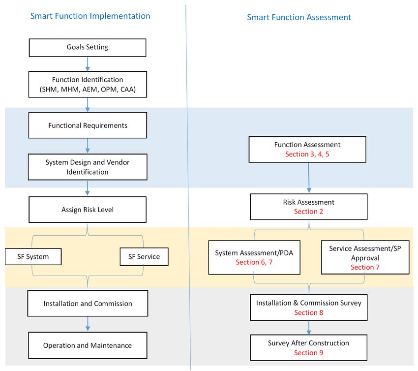
4 Goal-Based Framework
1/4 FIGURE 1 shows the goal-based framework for Smart Function implementation in the left-hand
column outlined in the ABS Guidance Notes for Smart Function Implementation with parallel
requirements for assessment as described in the indicated Sections of this Guide shown in the right-hand
column.
FIGURE 1
Smart Function Implementation and Assessment
ABS GUIDE FOR SMART FUNCTIONS FOR MARINE VESSELS AND OFFSHORE UNITS • 2021 11Section 1 General 1
4.1 Smart Function Implementation
This paragraph provides guidance on the general process that the SF implementation is to cover. The ABS
Guidance Notes for Smart Function Implementation may be used as a reference. This general process is to
be assessed by ABS following the methodology of 1/4.2.
4.1.1 Goal Setting
Smart Function implementation may achieve the following goals:
i) Increase health state awareness in order to enhance safety and asset integrity and to
minimize downtime associated with failures and maintenance;
ii) Improve asset efficiency and operational performance in order to reduce fuel
consumption, emissions and Operational Expenses (OPEX);
iii) Assist and augment crew with vessel operations related to navigation bridge management,
practices, and compliance reporting in order to enhance vessel situational awareness and
navigation safety, reduce crew workload, and minimize potential human error.
As classification requirements incorporate more vessel-specific and condition-based approaches,
properly implemented Smart Functions may augment the Surveyor’s understanding of the vessel’s
health state for more condition-based and less intrusive survey scopes.
4.1.2 Smart Function Identification
To achieve the goals described in 1/4.1.1, the appropriate SF categories as defined in 1/3.3 are to
be identified.
The following table aligns SF categories with common vessel functions, structures, and systems,
as applicable to marine vessels and offshore units. Similar categorization may apply to systems for
other vessel types, not explicitly referenced in 1/4.1.2 TABLE 2.
TABLE 2
Map of Smart Function Category to Vessel Function, Structure and
System
Health State Asset Efficiency & Crew Assistance &
Awareness Operational Augmentation
Vessel Function/Structure/System Performance
SHM MHM AEM OPM CAA
Propulsion System X X X
Steering/Maneuvering System X X X
Power Generation/Distribution X X X
Firefighting System/Equipment X
Auxiliary Machinery X X X
Drilling and Production X X X
Cargo/Ballast Handling System X X X X
Hotel/Accommodation/HVAC X X X
Global Hull X
Local Structures X
Shafting/Propeller X
ABS GUIDE FOR SMART FUNCTIONS FOR MARINE VESSELS AND OFFSHORE UNITS • 2021 12Section 1 General 1
Health State Asset Efficiency & Crew Assistance &
Awareness Operational Augmentation
Vessel Function/Structure/System Performance
SHM MHM AEM OPM CAA
Navigation X X X
Station Keeping/Mooring X X X X
Hull & Propeller Performance X X X
Compliance Reporting X
4.1.3 Functional Requirement
Functional requirements define a set of Smart Function tasks necessary to accomplish the
specified goals.
Functional requirements for individual SF categories eligible for notations are listed in Sections 3,
4, and 5 of this Guide.
4.1.4 System Design and Vendor identification
To realize the functional requirements set per 1/4.1.3, the SF system design and vendor(s) are to
be identified.
4.1.5 Risk Level Assignment
A risk level is to be assigned based on the procedure outlined in Section 2 by evaluating the
various risk factors associated with the Smart Function implementation.
The system technical requirements presented in Section 6 of this Guide are based on the assigned
risk level.
4.1.6 Smart Function System
The Smart Function system (or SF system in this Guide) is a combination of hardware and
software, including data source, data analytics algorithms, and models that realize the identified
Smart Functions and satisfy the functional requirements.
The hardware and software of the SF system can be centralized at one physical location or
decentralized across several locations onboard the vessel with or without onshore facility support.
4.1.7 Smart Function Service
The Smart Function service (or SF service in this Guide) is a human-in-the-loop process that
facilitates decision making for the SF system including actions related to anomaly detection,
structural and machinery health diagnostics and/or prognostics.
SF service delivery is to follow established and quality-controlled procedures by qualified and
competent staff. The SF service typically involves interaction and data exchanges with SF
systems.
The service delivery component of SF implementation is covered under Section 7.
4.2 Smart Function Assessment
The Smart Function implementation described in 1/4.1 and 1/4 FIGURE 1, is to be independently assessed
by ABS as outlined in 1/4.2.1 to 4.2.3 and summarized in 1/4.2.3 TABLE 3.
ABS GUIDE FOR SMART FUNCTIONS FOR MARINE VESSELS AND OFFSHORE UNITS • 2021 13Section 1 General 1
4.2.1 Function Assessment
Function assessment is the verification and validation procedure to confirm the capability and
scope of the Smart Function satisfy the implementation goals.
The function assessment requires verification through engineering review and Surveyor validation
through representative witnessing of functional achievement either at vendor site or on board the
vessel and is covered by the technical requirements of Subsections 3/6, 4/6 and 5/7.
4.2.2 System Assessment
System assessment is the verification and validation procedure to confirm that the SF system
hardware and software and its interaction and integration with onboard system(s) satisfies the
system technical requirements of the appropriate risk level. The system assessment covers the
following system properties:
i) Suitability for marine environment
ii) System integration and potential error propagation
iii) System reliability, maintenance, integrity and security
iv) Algorithm and model accuracy, system response time and capacity
The system assessment requires verification through engineering review and Surveyor validation
via onboard installation survey and onsite manufacture survey.
Detailed technical requirements for system assessment on hardware, software, data, data analytics
and model are summarized in Section 6 of this Guide.
4.2.3 Service Assessment
Service assessment is the verification and validation procedure to confirm the SF service
supported by Quality Assurance/Quality Control (QA/QC) procedures and practices, personnel
qualifications and competencies, to confirm that the service can be delivered consistently and
reliably for its intended purpose.
Service assessment requires verification through engineering review and Surveyor validation via
onsite audit. Detailed service assessment procedures and requirements are defined in Section 7 of
this Guide.
TABLE 3
Smart Function Assessment
Assessment Method
Intention Applicable to
Verification Validation
Function Smart Function SF capability and Engineering Representative demonstration
Assessment capability is defined scope review and/or functional test
and understood
System System satisfies the SF system hardware, Engineering Onboard (onsite) Survey
Assessment technical software (platform), review
requirements algorithm, model,
and data source
Service Service can be Procedure, process, Engineering Onsite audit, site/vessel
Assessment delivered staff qualification review validation by Surveyor
consistently and and competency,
reliably QA/QC
ABS GUIDE FOR SMART FUNCTIONS FOR MARINE VESSELS AND OFFSHORE UNITS • 2021 14Section 1 General 1
5 Guide Scope (1 October 2020)
This Guide is applicable to all marine vessels and offshore units, herein referred to as vessels.
This Guide covers the SF categories SHM and MHM as defined in 1/3.3, within the scope of optional
Smart Function class notations, SMART (INF), SMART (SHM) and/or SMART (MHM), SP approval,
and PDA as described in Subsections 1/6, and 1/8.
In order to keep this Guide concise, references in this Guide are made to requirements in the ABS Rules
for Building and Classing Marine Vessels (Marine Vessel Rules) and ABS Rules for Building and Classing
Mobile Offshore Units (MOU Rules). Where the requirements are not stated for other vessel types, similar
requirements will be applied. We recommend contacting ABS for clarification on applying these
requirements to vessels not covered by the Marine Vessel Rules and the MOU Rules.
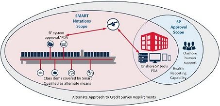
1/5 FIGURE 2 demonstrates the relationship of hardware and software approval to notation achievement
as well as the approval scope for Service Providers, and further illustrates the relationship of both these
scopes to implementation of alternate means to support Survey after construction.
FIGURE 2
Class Scope for Smart Functions (1 October 2020)
5.1 AEM, OPM and CAA Functions
Smart Functions for AEM, OPM, and CAA as defined in 1/3.3 may be enabled by the optional Smart
Function Notation SMART (INF).
ABS may recognize these Smart Functions via the verification and validation process defined in the ABS
Guidance Notes for Qualifying New Technologies while also considering the applicable requirements of
this Guide, the ABS Guidance Notes on Smart Function Implementation, and other relevant ABS and
industry standards.
Class Record Comments may be recorded as SMART (AEM), SMART (OPM), and/or SMART (CAA) to
recognize that the corresponding function has been reviewed by ABS, approved for “System Integration”
maturity, and installed on an ABS Classed vessel.
5.2 Semi-Autonomy and Full Autonomy (1 October 2021)
Functions operating at semi-autonomous or fully autonomous levels as defined in Subsection 1/2 are
outside of the scope of this Guide. For such applications, refer to the ABS Guide for Autonomous and
Remote Control Functions.
ABS GUIDE FOR SMART FUNCTIONS FOR MARINE VESSELS AND OFFSHORE UNITS • 2021 15Section 1 General 1
6 Class Notations
6.1 Smart Function Notations
The optional class notation SMART (xx, yy, etc.) is to be assigned to a vessel possessing a permanently
installed SF system. The implementation is to satisfy the function assessment and system assessment as
described in 1/6.1 TABLE 4.
The SF system can be installed during vessel construction or by retrofit.
The descriptive notation “xx, yy, etc.” can be any of the single notation, or a combination of the notations
listed here.
INF: Data INFrastructure for Smart Function implementation
SHM: Structural Health Monitoring
MHM: Machinery Health Monitoring
For example, SMART (INF, MHM) indicates a vessel with pre-installed data infrastructure and a
machinery health monitoring Smart Function system.
The SF covered vessel structure/system/equipment (see 1/4.1.2 TABLE 2 for examples) and their
corresponding Tiers (see Sections 4 and 5) are to be recorded in the vessel record notes.
TABLE 4
Requirements for Obtaining Smart Function Notations
Notation Applicable to Task Function Assessment System Assessment
Verification Functional requirements Technical requirements
(Sections 3, 4, 5) (Section 6)
INF, SHM, Smart Function Validation Onboard function test Installation survey and
MHM system(s) (Sections 8, 9) Surveys after Construction
(SAC)
(Sections 8, 9)
6.2 Maintenance of Smart Function Notations
To maintain the optional Smart Function notations of 1/6.1:
i) The SF system is to be kept properly maintained and operational. The survey after construction
requirements described in Section 9 are to be met and the survey is to be conducted to the
satisfaction of the attending Surveyor;
ii) Records of modifications, upgrades, and retrofits to the SF system, including both hardware and
software, are to be kept onboard and made available to the attending Surveyor.
6.3 Change of Vessel Ownership
Sale, change of vessel management, or transfer of class will result in reconsideration by ABS of SF system
approval, notations and class survey use.
7 Service Providers
ABS is to issue a certificate to approved Service Providers (SPs). SPs approved by ABS are listed on the
ABS website so that the information is verifiable and available to the industry.
ABS GUIDE FOR SMART FUNCTIONS FOR MARINE VESSELS AND OFFSHORE UNITS • 2021 16Section 1 General 1
The SP approval covers SHM and/or MHM functions. The requirements for obtaining a SP approval are
summarized in Section 1, Table 5. Refer to Section 7 of this Guide for the detailed procedure and
requirements for SP approval.
TABLE 5
Requirements for Obtaining SP Approval
SP Applicability Task Function System Assessment Service Assessment
Approval Assessment
OEM, Third Party Verification Functional PDA for hardware Procedure/staff/
Service Companies, requirements and software tools quality requirements
SHM, Shipyard, Owners and (Sections 4, 5) (Section 7) (Section 7)
MHM Operators that conduct
Validation Representative Tool deployment Onsite audit
Smart Function
service demonstration onsite survey (Section 7)
Operations
(Section 7) (Section 7)
8 Type Approval Program
8.1 Product Design Assessment
ABS may issue a Product Design Assessment (PDA) for the below systems reviewed under the Type
Approval program:
● System/equipment to deliver the Smart Function;
● Hardware and software that the SP uses for data handling, data analytics, and service delivery. The
tool and platform can be designed and developed by the SP or by a third-party.
The PDA is to follow the ABS Type Approval Program; refer to Appendices 1-1-A3 and 1-1-A4 of the
ABS Rules for Conditions of Classification (Part 1).
8.2 Product Design Assessment Attachment
When the Smart Function product is provided by OEMs as part of their system/equipment, ABS may issue
a PDA as an attachment to the approved system/equipment PDA. The approved Smart Function capability,
scope, applicable risk level, and alternate survey approach are to be recorded in the PDA Attachment.
The PDA attachment to be issued is unique for individual system/equipment types.
9 Alternate Means to Credit Survey Requirements (1 October 2020)
New technologies may enable less intrusive surveys of hull and machinery systems through alternative
means of verification of compliance to specific survey requirements. Alternative means of verification
involves determining the vessel’s health and maintenance status by leveraging data and digital capabilities
such as but not limited to, Smart Functions, system automated and self-verification testing, remote
inspection technologies, and remote verification and attendance through the ABS Remote Survey program.
Class items covered by Smart Function SHM and MHM may qualify for alternate means to credit survey
requirements. Machinery items are also to be enrolled in a Preventative Maintenance Program (PMP) in
accordance with the requirements of 7-A1-14 of the ABS Rules for Survey After Construction (Part 7)in
order to be considered for implementation of alternate means to credit survey requirements. Refer also to
Sections 4, 5, 7, 8 and 9 of this Guide.
ABS GUIDE FOR SMART FUNCTIONS FOR MARINE VESSELS AND OFFSHORE UNITS • 2021 17Section 1 General 1
10 Submittal Requirements
Section 1, Table 6 below summarizes the documents to be submitted to ABS for the optional Smart
Function class notations, Service Providers approval as well as PDA. Detailed description and
requirements on these submittals are listed in Appendix 3. ABS may request additional submittals.
TABLE 6
Submittal Requirements
For SF For SP
Submittal Requirements For PDA Assessment Requirements
Notation Approval
For Function Assessment
1. Concept of Operations X X X Sec. 3/4, INF Function Assessment Sec.
4/6, SHM Function Assessment Sec. 5/7,
2. Smart Function Risk Level X X
MHM Function Assessment Sec. 7/7, SP
3. Smart Function Description X X X Approval
4. Stakeholder Role Matrix for X X
Implementation
For System Assessment
5. SF System Architecture X X* X Sec. 6, System Assessment
(*) submittals to include system
6. SF System Specification X X* X
specification to cover applicable
7. Additional Specification for Medium X X* X requirements of Sec 6
and High Risk Levels
8. Installation and Commissioning Plan X Sec. 8, Installation and Commissioning
Survey
For Service Assessment
9. Organizational Capability X Sec. 7/7, SP Approval
Sec. 8, Installation and deployment
10. Tool Development and Deployment X
Process
11. Data Center Support X
11 Application of New Technologies
Smart Functions in marine and offshore applications are built upon information technology, data science,
software, and cybersecurity. It is foreseen that as these evolve, new and alternative capabilities and
technologies not yet described within this Guide may be implemented on board ABS Classed vessels.
ABS will accept new capabilities and technologies on a case-by-case basis following the goal-based
framework and risk-informed approach established in this Guide, the ABS Guidance Notes on Smart
Function Implementation, the ABS Guidance Notes on Review and Approval of Novel Concepts and the
ABS Guidance Notes on Qualifying New Technologies.
12 Damage, Failure and Repair (1 July 2020)
Damage, failure, or deterioration detected by the implemented SHM or MHM Smart Function to hull,
machinery, or equipment which affects or may affect classification, is to be submitted by the Owners or
their representatives for examination by a Surveyor at first opportunity. All repairs found necessary by the
Surveyor are to be carried out to the Surveyor’s satisfaction. Refer to 1-1-8/1 of ABS Rules for Conditions
of Classification (Part 1).
ABS GUIDE FOR SMART FUNCTIONS FOR MARINE VESSELS AND OFFSHORE UNITS • 2021 18SECTION 2
Risk Categorization
1 General
This Guide uses a risk-informed approach to set the prescriptive requirements for ABS verification and
validation activities. The risk level is to be assigned by the submitter with consideration of the safety
related risk factors and the potential consequences of the Smart Function failure or under-performance on
the vessel’s safety and operations.
Consideration of commercial risk is an important concept during a Smart Function implementation.
However, a commercial risk assessment is not required to obtain optional Smart Function notations, SP
approval, or PDA attachment, and thus is not within the scope of this Guide.
The requirements for system assessment as described in Section 6, are based on the Smart Function’s risk
level assigned by the process described in Subsection 2/2.
2 Assignment of Risk Level
Each Smart Function submitted to ABS for approval is to be assigned a risk level by the submitter based
on the approach described below.
2.1 Likelihood of Failure
The likelihood of a Smart Function failure or under-performance is to be determined by:
i) The complexity level of Smart Function system, service, and their integration and interaction
(denoted as SFN)
ii) The highest sophistication level of the data analytics and model employed (denoted as SDA)
The characteristics levels for the complexity level of Smart Function Network (SFN) and highest
Sophistication level of Data Analysis method employed (SDA) are defined in Section 2, Table 1.
TABLE 1
Smart Function Likelihood Characteristics Levels
Complexity Level of Smart Function System and Service (SFN)
0 Simple (Standalone system)
1 Simple Network (Partial integration with other systems, not all systems networked)
2 Complex Network (All networked and fully integrated, onboard access only)
3 Multi-Attribute Connected (Remote and onshore accesses, onboard function relies on onshore support and
continuous and reliable vessel-onshore communication)
ABS GUIDE FOR SMART FUNCTIONS FOR MARINE VESSELS AND OFFSHORE UNITS • 2021 19Section 2 Risk Categorization 2
Highest Sophistication Level of Data Analysis Employed (SDA)
0 Basic (Parameter monitoring, statistics and trending)
1 Physics Based Models and Traditional Condition Monitoring Techniques with Analytics Support
2 Data Driven Models (Machine learning and Artificial Intelligence (AI) models, with or without use of physics-
based models)
The likelihood of Smart Function under-performance or failure is defined as the summation of the assigned
levels of above key likelihood characteristics (SFN + SDA) and is represented by the three likelihood
levels defined in Section 2, Table 2.
TABLE 2
Likelihood Levels of Failure or Under-Performance
Likelihood Level SFN+SDA Example
L (Low) 0, 1 Hull girder bending moment and slamming monitoring with strain
gauges and accelerometers
M (Medium) 2, 3 Engine cylinder temperature and pressure monitoring with integrated
thermal and pressure sensors
H (High) 4, 5 Voyage optimization (periodical weather forecast feeding, operational
parameters collected from relevant onboard systems, data-driven fuel
consumption model)
2.2 Consequence of Failure
The consequence level denotes the potential impact of the Smart Function failure or underperformance on
the vessel safety and operation. The consequence level is influenced by the following three factors:
i) The Smart Function level of Decision-making support (denoted as SFD)
ii) The Smart Function Integration level with the onboard systems (denoted as SFI)
iii) The System Category that the Smart Function integrates with (denoted as SC)
The decision-making support (SFD) and integration level (SFI) are defined in Section 2, Table 3.
TABLE 3
Smart Function Decision-Making Support and Integration Level
Smart Function Level of Decision-Making (SFD)
0 Dashboard and Auto Reporting of Health, Performance, and Situational Awareness State
1 Decision Recommendations (Human take action)
2 Auto-Initiated Actions with Human’s Supervision (Human in-the-loop)
Smart Function Integration Level (SFI)
0 Standalone (Isolated from other systems, or passive listening only for data collection when integrated with
onboard systems. No potential impact on the integrated system’s safety and performance)
1 Partial (one-way data communication to the Smart Function with active data request. May cause performance
degradation but there is no safety impact on the integrated onboard system)
2* Fully Integrated (two-way communication with onboard systems with the potential sending commands to the
systems for operational adjustment or optimization)
ABS GUIDE FOR SMART FUNCTIONS FOR MARINE VESSELS AND OFFSHORE UNITS • 2021 20Section 2 Risk Categorization 2
Note: Auto-initiated actions (SFD = 2) typically require full integration level (SFI = 2).
When Smart Functions are integrated with vessel systems (usually via an interface to the computer-based
systems for control and alarming), a failure of the Smart Function may propagate to the integrated
computer-based system and therefore expose the vessel to risk.
System Category (SC) is defined in 4-9-3/Table 1 of the Marine Vessel Rules according to the potential
extent of the damage that may be caused by a single failure within the computer-based system. This
categorization, implemented in this Guide for marine vessels and offshore units, is shown in Section 2,
Table 4.
TABLE 4
System Categories (SC)
System Category Effects of Failure Typical System Functionality
Failure will not lead to dangerous situations for Monitoring function for informational/
I human safety, safety of the vessel and/or threat administrative tasks
to the environment
Failure could eventually lead to dangerous Alarm and monitoring functions
situations for human safety, safety of the vessel Control functions which are necessary to
II
and/or threat to the environment. maintain the ship in its normal operational and
habitable conditions
Failure could immediately lead to dangerous Control functions for maintaining the vessel’s
III situations for human safety, safety of the vessel propulsion and steering
and/or threat to the environment. Vessel safety functions
Examples of assignment to system categories are shown in 4-9-3A2/5 of the Marine Vessel Rules and listed
below. For similar system categories for other vessel types not listed below, refer to the applicable ABS
Rules and Guides
i) Systems Typically Belonging to Category I:
● Maintenance support systems
● Information systems
ii) Systems Typically Belonging to Category II:
● Liquid cargo transfer control system
● Bilge level detection and associated control of pumps
● Fuel oil treatment system
● Ballast transfer valve remote control system
● Stabilization and ride control systems
● Alarm and monitoring systems for propulsion systems
iii) Systems Typically Belonging to Category III:
● Propulsion system of a ship, meaning the means to generate and control mechanical thrust in
order to move the ship (devices used only during maneuvering, such as bow tunnel thrusters,
are not in this scope)
● Steering system control system
● Electric power system (including power management system)
ABS GUIDE FOR SMART FUNCTIONS FOR MARINE VESSELS AND OFFSHORE UNITS • 2021 21Section 2 Risk Categorization 2
● Ship safety systems covering fire detection and fighting, flooding detection and fighting,
internal communication systems involved in evacuation phases, and ship systems involved in
operating lifesaving appliances
● Dynamic positioning system of equipment classes 2 and 3 according to IMO MSC/Circ.645 or
MSC.1/Circ.1580
● Drilling systems
The consequence of a Smart Function failure or under-performance is defined by the below formula and
represented by the three levels defined in Section 2, Table 5.
SFD + (SFI × SC)
TABLE 5
Smart Function Failure – Consequence Levels
Consequence Level SFD + (SFI x SC) Example
L (Low) 0, 1 Hull girder condition monitoring (dashboard with installed strain gauges)
M (Medium) 2, 3, 4 Weather routing (route recommendations and passive data collection
from relevant systems)
H (High) 5 and above Power management and optimization (auto-adjusting engine operational
parameters with certain range for best performance)
2.3 Risk Matrix
A risk matrix is to be utilized based on the level of likelihood and consequence described in 2/2.1 and
2/2.2, respectively, and as shown in Section 2, Table 6.
The risk matrix is to be utilized to assign a risk level (L: Low, M: Medium, H: High) to each of the Smart
Functions implemented on each vessel.
TABLE 6
Risk Matrix
Likelihood Level
Consequence Level
L M H
L L L M
M M M H
H M H H
3 Risk Assessment
For the Smart Functions that are assigned a high-risk level, a Functional Failure Modes, Effects and
Criticality Analysis (FMECA) approach and Management of Change (MoC) process to address potential
new risks to the vessel or unit are to be performed by the submitter. Based on the results of the functional
FMECA, a component level FMECA is to be conducted when deemed necessary by ABS when:
i) A particularly critical subsystem, hardware and software component, data source, algorithm and
analytics model are identified during the functional FMECA;
ii) Critical functions with a risk level high are identified during the functional FMECA;
ABS GUIDE FOR SMART FUNCTIONS FOR MARINE VESSELS AND OFFSHORE UNITS • 2021 22Section 2 Risk Categorization 2
Standard engineering evaluation can be used to demonstrate compliance with the stated design philosophy
in lieu of the component FEMCA assessment for simple system and physics-based models. Use of a
Standard engineering evaluation to replace the component FMECA assessment may be accepted upon
approval by ABS.
3.1 Functional FMECA for Smart Functions
A Functional FMECA can be used to systematically identify and assess the potential risks to the vessel’s
safety and operation relevant to the Smart Function implementation.
3.1.1 Scope
The scope of the Functional FMECA is to include the risks associated with the Smart Function,
including its hardware, software, data analytics and models, data integrity, cybersecurity,
communication and interaction as well as its integration with onboard control and automation
systems.
3.1.2 Objective
The objectives of the risk assessment are to at least include the following:
i) Assess the impact of functional failure of the Smart Functions to the vessel’s safety and
operability by conducting criticality analyses;
ii) Identify the failure modes and fail-safe state for the Smart Function system and actions
required to reach the state under various operational modes;
iii) Identify any hazardous situations originating from the Smart Function and the potential
impact on other vessel systems through integration or interactions;
iv) Evaluate if the existing safeguards are adequate and identify if additional safeguards are
required to mitigate the risks for the design and operation of the Smart Function, when
necessary.
3.1.3 Risk Factor
During the risk assessment, the following Smart Function risk factors are to be considered, as a
minimum:
i) The role of the Smart Function, in terms of decision support and decision making;
ii) The complexity of the hardware, software, data analytics, algorithm and model;
iii) The reliability of the hardware, software, network and data communication;
iv) The redundancy of the onboard automation and control systems;
v) Loss of power supply;
vi) The uncertainty of analytics models, data, and data quality;
vii) The accuracy and robustness of the algorithm and analytics models;
viii) Data integrity, software quality and cybersecurity;
ix) Operation errors and human factors;
x) Potential integrity impacts on data;
xi) Potential corruption from integration and interoperability issues (i.e., from software and
system interface incompatibilities).
3.1.4 Risk Assessment Plan
A risk assessment plan is to be developed and submitted to ABS prior to conducting the
Functional FMECA study. The risk assessment criteria for evaluation (i.e., risk matrix) is to be
ABS GUIDE FOR SMART FUNCTIONS FOR MARINE VESSELS AND OFFSHORE UNITS • 2021 23You can also read