USER MANUAL Gateway for integration of Mitsubishi Heavy Industries air conditioners into KNX TP-1 (EIB) control systems - Intesis
←
→
Page content transcription
If your browser does not render page correctly, please read the page content below

Gateway for integration of Mitsubishi Heavy Industries air
        conditioners into KNX TP-1 (EIB) control systems

                                  Application’s Program Version: 1.1

                                                 USER MANUAL
                                         Issue date: 07/2020 r2.2 ENGLISH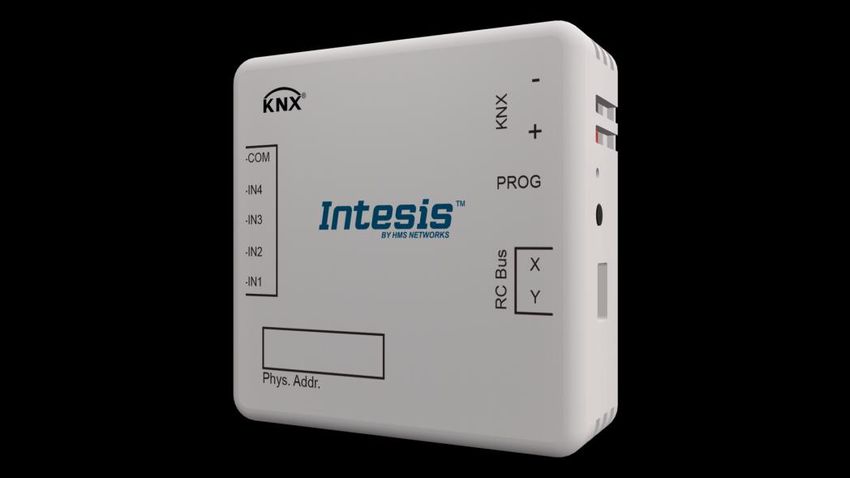
IntesisTM KNX – Mitsubishi Heavy Industries A.C.                                          User's manual r2.2 EN

Important User Information
Disclaimer
The information in this document is for informational purposes only. Please inform HMS Industrial
Networks of any inaccuracies or omissions found in this document. HMS Industrial Networks disclaims
any responsibility or liability for any errors that may appear in this document.

HMS Industrial Networks reserves the right to modify its products in line with its policy of continuous
product development. The information in this document shall therefore not be construed as a
commitment on the part of HMS Industrial Networks and is subject to change without notice. HMS
Industrial Networks makes no commitment to update or keep current the information in this document.

The data, examples and illustrations found in this document are included for illustrative purposes and are
only intended to help improve understanding of the functionality and handling of the product. In view of
the wide range of possible applications of the product, and because of the many variables and
requirements associated with any particular implementation, HMS Industrial Networks cannot assume
responsibility or liability for actual use based on the data, examples or illustrations included in this
document nor for any damages incurred during installation of the product. Those responsible for the use
of the product must acquire sufficient knowledge in order to ensure that the product is used correctly in
their specific application and that the application meets all performance and safety requirements
including any applicable laws, regulations, codes and standards. Further, HMS Industrial Networks will
under no circumstances assume liability or responsibility for any problems that may arise as a result from
the use of undocumented features or functional side effects found outside the documented scope of the
product. The effects caused by any direct or indirect use of such aspects of the product are undefined and
may include e.g. compatibility issues and stability issues.

© HMS Industrial Networks S.L.U. - All rights reserved                                        URL   https://www.intesis.com
This information is subject to change without notice

                                                                                                               2 / 59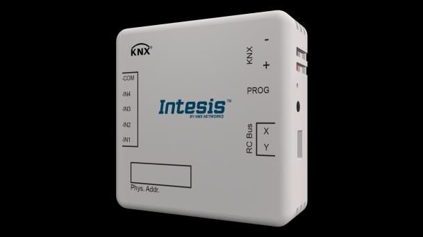
IntesisTM KNX – Mitsubishi Heavy Industries A.C.         User's manual r2.2 EN

Gateway for integration of Mitsubishi Heavy
Industries (MHI) air conditioners into KNX TP-1
(EIB) control systems.
Compatible with RAC* Series, FD Series, KX6 and KXR6 (VRF)
Series air conditioners commercialized by Mitsubishi Heavy
Industries.

*RAC Series require optional SC-BIKN-E from MHI.

Application’s Program Version: 1.1

ORDER CODE                          LEGACY ORDER CODE
INKNXMHI001R000                     MH-RC-KNX-1i

© HMS Industrial Networks S.L.U. - All rights reserved      URL   https://www.intesis.com
This information is subject to change without notice

                                                                             3 / 59
IntesisTM KNX – Mitsubishi Heavy Industries A.C.                                               User's manual r2.2 EN

INDEX

1.    Presentation .................................................................................................... 6
2.    Connection ...................................................................................................... 7
  2.1    INKNXMHI001R000 without MHI Remote Controller ........................................... 7
  2.2    INKNXMHI001R000 with MHI Remote Controller ............................................... 7
3.    Configuration and setup .................................................................................... 9
4.    ETS Parameters ............................................................................................. 10
  4.1    General dialog ............................................................................................ 11
    4.1.1    INKNXMHI001R000 is master in X Y bus .................................................. 11
    4.1.2    Send READs for Control_ objects on bus recovery ..................................... 11
    4.1.3    Scene to load on bus recovery / startup ................................................... 11
    4.1.4    Disallow control from remote controller .................................................... 12
    4.1.5    Enable func “Control_ Lock Control Obj” ................................................... 12
    4.1.6    Enable use of objects for Filter ................................................................ 13
    4.1.7    Enable func “Operating Hours Counter” .................................................... 13
    4.1.8    Enable object “Error Code [2byte]” .......................................................... 13
    4.1.9    Enable object “Error Text Code [14byte]” ................................................. 14
  4.2    Mode Configuration dialog ............................................................................ 14
    4.2.1    Indoor unit has AUTO mode.................................................................... 15
    4.2.2    Enable use of Heat / Cool bit-type obj ...................................................... 15
    4.2.3    Enable PID-Compat. Scaling Mode Objects ............................................... 15
    4.2.4    Enable use of +/- object for Mode ........................................................... 16
    4.2.5    Enable use of bit-type Mode objects (for control) ...................................... 17
    4.2.6    Enable use of bit-type Mode objects (for status)........................................ 17
    4.2.7    Enable use of Text object for Mode .......................................................... 17
  4.3    Special Modes Configuration dialog ................................................................ 18
    4.3.1    Enable use of POWER mode .................................................................... 18
    4.3.2    Enable use of ECONOMY mode ................................................................ 19
    4.3.3    Enable use of ADDITIONAL HEATING mode .............................................. 20
    4.3.4    Enable use of ADDITIONAL COOLING mode .............................................. 21
  4.4    Fan Speed Configuration dialog ..................................................................... 21
    4.4.1    Available fanspeeds in Indoor Unit........................................................... 22
    4.4.2    DPT object type for fanspeed .................................................................. 22
    4.4.3    Enable use of +/- object for Fan Speed .................................................... 23
    4.4.4    Enable use of bit-type Fan Speed objects (for Control) ............................... 24
    4.4.5    Enable use of bit-type Fan Speed objects (for Status) ................................ 24
    4.4.6    Enable use of Text object for Fan Speed ................................................... 25
  4.5    Vanes Up-Down Configuration dialog ............................................................. 25
    4.5.1    Indoor unit has U-D Vanes ..................................................................... 26
    4.5.2    DPT object type for Vanes Up-Down ........................................................ 26
    4.5.3    Enable use of +/- object for Vanes U-D .................................................... 27
    4.5.4    Enable use of bit-type Vane U-D objects (for Control) ................................ 28
    4.5.5    Enable use of bit-type Vane U-D objects (for Status) ................................. 28
    4.5.6    Enable “Vanes U-D Swing” objects (for Control and Status) ........................ 29
    4.5.7    Enable use of Text object for Vane U-D .................................................... 29
  4.6    Temperature Configuration dialog.................................................................. 30
    4.6.1    Periodic sending of “Status_ AC Setp” ...................................................... 30
    4.6.2    Transmission of “Status_ AC Reference Temp” .......................................... 30
    4.6.3    Enable use of +/- object for Setpoint Temp .............................................. 31
    4.6.4    Enable limits on Control_ Setpoint obj ..................................................... 31
    4.6.5    Ambient temp. ref. is provided from KNX ................................................. 32
  4.7    Scene Configuration dialog ........................................................................... 33
    4.7.1    Enable use of scenes ............................................................................. 33
    4.7.2    Scenes can be stored from KNX bus ........................................................ 33
    4.7.3    Enable use of bit objects for scene execution ............................................ 34
    4.7.4    Scene “x” preset ................................................................................... 34
  4.8    Switch-Off Timeouts Configuration dialog ....................................................... 36

© HMS Industrial Networks S.L.U. - All rights reserved                                             URL   https://www.intesis.com
This information is subject to change without notice

                                                                                                                    4 / 59
IntesisTM KNX – Mitsubishi Heavy Industries A.C. User's manual r2.2 EN
4.8.1 Enable use of Open Window / Switch off timeout function .......................... 36
4.8.2 Enable use of Occupancy function ........................................................... 38
4.8.3 Enable use of SLEEP timeout .................................................................. 40
4.9 Binary Input “x” Configuration dialog ............................................................. 40
4.9.1 Enable use of Input “x” .......................................................................... 41
4.9.2 Contact type ......................................................................................... 41
4.9.3 Debounce time ..................................................................................... 41
4.9.4 Disabling function.................................................................................. 41
4.9.5 Function ............................................................................................... 42
5. Specifications................................................................................................. 50
6. AC Unit Types compatibility. ............................................................................ 51
7. Error Codes ................................................................................................... 52
Appendix A – Communication Objects Table ................................................................ 53
© HMS Industrial Networks S.L.U. - All rights reserved URL https://www.intesis.com
This information is subject to change without notice
5 / 59IntesisTM KNX – Mitsubishi Heavy Industries A.C. User's manual r2.2 EN
1. Presentation
INKNXMHI001R000 allows a complete and natural integration of
MITSUBISHI HEAVY INDUSTRIES air conditioners with KNX control
systems.
Compatible with RAC* Series, FD Series, KX6 and KXR6 (VRF) Series
air conditioners commercialized by MITSUBISHI HEAVY INDUSTRIES.
Main features:
• Reduced dimensions, quick installation.
• Multiple objects for control and status (bit, byte, characters…) with KNX standard
datapoint types.
• Status objects for every control available.
• Timeout for Open Window and Occupancy. Sleep function also available.
• Control of the AC unit based in the ambient temperature read by the own AC unit, or in
the ambient temperature read by any KNX thermostat.
• AC unit can be controlled simultaneously by the wired remote control of the AC unit and
by KNX.
• Direct connection to the AC indoor units. Up to 16 AC indoor units can be connected to
MH-RC-MBS-1, controlling them as one (not individually).
• Total Control and Monitoring of the AC unit from KNX, including monitoring of AC unit’s
state of internal variables, running hours counter (for filter maintenance control), and
error indication and error code.
• Up to 5 scenes can be saved and executed from KNX, fixing the desired combination of
Operation Mode, Set Temperature, Fan Speed, Vane Position and Remote Controller
Lock in any moment by using a simple switching.
• Four potential-free binary inputs provide the possibility to integrate many types of external
devices. Also configurable from ETS, they can be used for switching, dimming, shutter/blind
control, and more
© HMS Industrial Networks S.L.U. - All rights reserved URL https://www.intesis.com
This information is subject to change without notice
6 / 59IntesisTM KNX – Mitsubishi Heavy Industries A.C. User's manual r2.2 EN
2. Connection
Connection of the INKNXMHI001R000 to the AC indoor unit
2.1 INKNXMHI001R000 without MHI Remote Controller
The INKNXMHI001R000 can be connected directly to the X/Y bus of the indoor unit (no MHI
remote controller -RC from now on- also connected in the X/Y bus). If this is the case,
INKNXMHI001R000 must be configured as master (using the ETS software), see connection
diagram below.
2.2 INKNXMHI001R000 with MHI Remote Controller
If a MHI remote controller (RC) is present and connected to the X/Y bus, there are two
configuration options:
• Wired remote control available. Connect the gateway as Slave in parallel with the
wired remote controllers (controller acts as Master).
• Infrared remote control available. Connect the gateway as Master in parallel with
the infrared remote controller (Infrared receiver acts as Slave).
Figure 2.1 MHI RC PCB backside, Master/Slave switch
Disconnect mains power from the AC unit and use a 2 wire cable with a diameter of
0.75mm2 to 1.25mm2 for the connection of INKNXMHI001R000, Mitsubishi Heavy Industries
remote controller and its corresponding indoor unit. Screw the suitably peeled cable ends in
the corresponding X/Y terminals of each device, as summarized in the Figure 2.2.
Maximum X/Y bus length is 600 meter. MHI RC and INKNXMHI001R000 are no polarity
dependent.
Connection of the INKNXMHI001R000 to the KNX bus:
Disconnect power of the KNX bus. Connect the INKNXMHI001R000 to the KNX TP-1 (EIB)
bus using the KNX standard connector (red/grey) of the INKNXMHI001R000, respect
polarity.
Reconnect power of the KNX bus, and mains power of the AC unit.
© HMS Industrial Networks S.L.U. - All rights reserved URL https://www.intesis.com
This information is subject to change without notice
7 / 59IntesisTM KNX – Mitsubishi Heavy Industries A.C. User's manual r2.2 EN
Connection diagrams:
INKNXMHI001R000 without MHI RC
Binary inputs for potential-free
contacts.
KNX TP-1
AC Indoor Unit KNX
COM
(EIB) bus
IN4
IN3
AC Unit X
IN2
IN1
Y
Internal
electronic
control Connection to X/Y bus.
Two wire cable.
X
Y
Max.600 m
INKNXMHI001R000 with MHI RC
Binary inputs for potential-free
Control Remoto contacts.
MHI
AC Indoor Unit KNX TP-1
KNX
COM
(EIB) bus
IN4
IN3
AC Unit X
IN2
Y
X Y IN1
Internal
electronic
control Connection to X/Y bus.
Two wire cable.
X
Y
Max. 600 m
Figure 2.2 INKNXMHI001R000 connection diagrams
© HMS Industrial Networks S.L.U. - All rights reserved URL https://www.intesis.com
This information is subject to change without notice
8 / 59IntesisTM KNX – Mitsubishi Heavy Industries A.C. User's manual r2.2 EN
3. Configuration and setup
This is a fully compatible KNX device which must be configured and setup using standard
KNX tool ETS.
ETS database for this device can be downloaded from:
https://intesis.com/products/ac-interfaces/mitsubishi-heavy-industries-gateways/mitsubishi-heavy-knx-inputs-vrf-mh-rc-
knx-1i
Please consult the README.txt file, located inside the downloaded zip file, to find
instructions on how to install the database.
Important: Do not forget to select the correct settings of AC indoor unit being
connected to the INKNXMHI001R000. This is in "Parameters" of the device in ETS.
© HMS Industrial Networks S.L.U. - All rights reserved URL https://www.intesis.com
This information is subject to change without notice
9 / 59IntesisTM KNX – Mitsubishi Heavy Industries A.C. User's manual r2.2 EN
4. ETS Parameters
When imported to the ETS software for the first time, the gateway shows the following
default parameter configuration:
Figure 4.1 Default parameter configuration
With this configuration it’s possible to send On/Off (Control_ On/Off), change the AC Mode
(Control_ Mode), the Fan Speed (Control_ Fan Speed) and also the Setpoint Temperature
(Control_ Setpoint Temperature). The Status_ objects, for the mentioned Control_ objects,
are also available to use if needed. Also objects Status_ AC Reference Temp and Status_
Error/Alarm are shown.
Figure 4.2 Default communication objects
© HMS Industrial Networks S.L.U. - All rights reserved URL https://www.intesis.com
This information is subject to change without notice
10 / 59IntesisTM KNX – Mitsubishi Heavy Industries A.C. User's manual r2.2 EN
4.1 General dialog
Inside this parameter’s dialog it is possible to activate or change the parameters shown in
the Figure 4.1.
The first field shows the URL where to download the database and the user manual for the
product.
4.1.1 INKNXMHI001R000 is master in X Y bus
This parameter changes the gateway’s behavior, being able to program it as master or slave
in X Y bus.
o If set to “no”, the gateway will work as a slave and it will be necessary to have a BRC
remote controller configured as a master.
o If set to “yes” the gateway will be master of the bus. It is not necessary to have any
BRC remote controller in this case but, if there are, they must be configured as slaves.
The next parameter is also shown when selecting INKNXMHI001R000 as master in X Y
bus:
Figure 4.3 Parameter detail
4.1.2 Send READs for Control_ objects on bus recovery
When this parameter is enabled, INKNXMHI001R000 will send READ telegrams for the group
addresses associated on its Control_ objects on bus recovery or application reset/start-up.
o If set to “no” the gateway will not perform any action.
o If set to “yes” all Control_ objects with both Transmit (T) and Update (U) flags enabled
will send READs and their values will be updated with the response when received.
Figure 4.4 Parameter detail
➢ Delay before sending READs (sec):
With this parameter, a delay can be configured between 0 and 30 seconds for the
READs sent by the Control_ objects. This is to give time enough to other KNX
devices on the bus to start-up before sending the READs.
4.1.3 Scene to load on bus recovery / startup
This parameter executes a selected scene on bus recovery or startup, only if the selected
scene has an enabled preset or values previously saved from KNX bus (see Scene
Configuration dialog).
© HMS Industrial Networks S.L.U. - All rights reserved URL https://www.intesis.com
This information is subject to change without notice
11 / 59IntesisTM KNX – Mitsubishi Heavy Industries A.C. User's manual r2.2 EN
If the gateway is disconnected from the indoor unit the scene will not be applied, even when
connecting to the indoor unit again.
Figure 4.5 Parameter detail
4.1.4 Disallow control from remote controller
This parameter allows:
1- Having the remote controller always locked, or
2- Decide through a new communication object if the RC is locked or not.
o If set to “yes” all the actions performed through the remote controller will be disabled.
o If set to “no” the remote controller will work as usually. It also appears a new
parameter and the communication object Control_ Lock Remote Control.
32
Figure 4.6 Communication object and parameter detail
➢ Enable comm obj “Ctrl_ Remote Lock”:
If set to “no” the object will not be shown.
If set to “yes” the Control_ Lock Remote Control object will appear.
• When a “1” value is sent to this communication object, the remote controller
is locked. To be unlocked a “0” value must be sent. The gateway remembers
the last value received even if a KNX bus reset/failure happens.
Important: If an initial scene is enabled and it has as Value for Remote Lock
(unchanged) or unlocked, this would unlock the remote controller because the
initial scene has priority over the Control_ Lock Remote Control
communication object.
4.1.5 Enable func “Control_ Lock Control Obj”
This parameter shows/hide the Control_ Lock Control Obj communication object which,
depending on the sent value, locks or unlocks ALL the Control_ communication objects
except itself.
33
o If set to “no” the object will not be shown.
o If set to “yes” the Control_ Lock Control Objects object will appear.
© HMS Industrial Networks S.L.U. - All rights reserved URL https://www.intesis.com
This information is subject to change without notice
12 / 59IntesisTM KNX – Mitsubishi Heavy Industries A.C. User's manual r2.2 EN
• When a “1” value is sent to this communication object, all the Control_
objects will be locked. To unlock a “0” value must be sent, as the gateway
remembers the last value received even if a KNX bus reset/failure happens.
4.1.6 Enable use of objects for Filter
This parameter shows/hides Control_ Reset Filter and Status_ Filter Status that lets reset
the filter status and also monitor if there is a filter alarm.
27
78
o If set to “no” the object will not be shown.
o If set to “yes” Control_ Reset Filter and Status_ Filter Status objects will appear.
• When a “0” value is shown in the Status_ object, it indicates no filter alarm.
When a “1” value is shown in the Status_ object, it indicates that the filter is
full. Once the filter has been cleaned, alarm should be reset sending a “1”
value to the Control_ Reset Filter object.
4.1.7 Enable func “Operating Hours Counter”
This parameter shows/hides the Status_ Operation Hour Counter communication object
which counts the number of operating hours for the INKNXMHI001R000.
86
o If set to “no” the object will not be shown.
o If set to “yes” the Status_ Operation Hour Counter object will appear.
• This object can be read and sends its status every time an hour is counted.
The gateway keeps that count in memory and the status is sent also after a
KNX bus reset/failure. Although this object is marked as a Status_ object it
also can be written to update the counter when needed. To reset the counter
should be written a “0” value.
Important: This object comes by default without the write (W) flag
activated. If is necessary to write on it, this flag must be activated.
Important: This object will also return its status, every time a value is
written, only if it’s different from the existing one.
Important: If the stored value is 0 hours, the gateway will not send the
status to KNX.
4.1.8 Enable object “Error Code [2byte]”
This parameter shows/hides the Status_ Error Code communication object which shows the
indoor unit errors, if occurred, in numeric format.
© HMS Industrial Networks S.L.U. - All rights reserved URL https://www.intesis.com
This information is subject to change without notice
13 / 59IntesisTM KNX – Mitsubishi Heavy Industries A.C. User's manual r2.2 EN
80
o If set to “no” the object will not be shown.
o If set to “yes” the Status_ Error Code [2byte] object will appear.
• This object can be read and also sends the indoor unit error, if occurred, in
numeric format. If a “0” value is shown that means no error.
4.1.9 Enable object “Error Text Code [14byte]”
This parameter shows/hides the Status_ Error Text Code communication object which
shows the indoor unit errors, if occurred, in text format.
81
o If set to “no” the object will not be shown.
o If set to “yes” the Status_ Error Text Code object will appear.
• This object can be read and also sends the indoor unit error, if occurred, in
text format. The errors shown have the same format as at the remote
controller and at the error list from the indoor unit manufacturer. If the
object’s value is empty that means no error.
4.2 Mode Configuration dialog
Figure 4.7 Default Mode Configuration dialog
All the parameters in this section are related with the different mode properties and
communication objects.
1
The byte-type communication object for Mode works with the DTP_20.105. Auto mode will
be enabled with a “0” value, Heat mode with a “1” value, Cool mode with a “3” value, Fan
mode with a “9” value and Dry mode with a “14” value.
© HMS Industrial Networks S.L.U. - All rights reserved URL https://www.intesis.com
This information is subject to change without notice
14 / 59IntesisTM KNX – Mitsubishi Heavy Industries A.C. User's manual r2.2 EN
4.2.1 Indoor unit has AUTO mode
This parameter has to be used to indicate if the indoor unit has the auto mode available.
o If set to “no”, the indoor unit doesn’t have the auto mode available.
o If set to “yes”, the infoor unit has the auto mode available.
Important: Read the documentation of your indoor unit to check if it has AUTO mode
available.
4.2.2 Enable use of Heat / Cool bit-type obj
This parameter shows/hides the Control_ and Status_ Mode Cool/Heat communication
objects.
2
55
o If set to “no” the objects will not be shown.
o If set to “yes” the Control_ and Status_ Mode Cool/Heat objects will appear.
• When a “1” value is sent to the Control_ communication object, Heat mode
will be enabled in the indoor unit, and the Status_ object will return this
value.
• When a “0” value is sent to the Control_ communication object, Cool mode
will be enabled in the indoor unit, and the Status_ object will return this
value.
4.2.3 Enable PID-Compat. Scaling Mode Objects
This parameter shows/hides the Control_ Mode Cool & On and Control_ Mode Heat & On
communication objects.
3
4
o If set to “no” the objects will not be shown.
o If set to “yes” the Control_ Mode Cool & On and Control_ Mode Heat & On objects will
appear.
• These objects provide compatibility with those KNX thermostats that control
the demand of heating or cooling by using scaling (percentage) objects. In
these thermostats, the percentage demand is meant to be applied on a fluid
valve of the heating / cooling system.
• INKNXMHI001R000 device does not provide individual control on the internal
parts of the indoor unit (as can be its compressor, refrigerant valves, etc).
Rather, it provides the same level of control as a (user) remote controller.
© HMS Industrial Networks S.L.U. - All rights reserved URL https://www.intesis.com
This information is subject to change without notice
15 / 59IntesisTM KNX – Mitsubishi Heavy Industries A.C. User's manual r2.2 EN
• Objects “Control_ Mode Cool & On” and “Control_ Mode Heat & On” intend to
bring compatibility between thermostats oriented to the control of custom
heating / cooling systems and ready-made AC indoor units, by applying the
following logic:
• Whenever a non-zero value (>0%) is received at “Control_ Mode Cool
& On”, indoor unit will switch On in COOL mode.
• Whenever a non-zero value (>0%) is received at “Control_ Mode Heat
& On”, indoor unit will switch On in HEAT mode.
• Lastest updated object will define the operating mode
• Indoor unit will switch off only when both objects become zero (0%) –
or when an OFF is requested at object “0. On/Off [DPT_1.001 - 1bit]”
Important: These objects function is only to send On/Off and Cool/Heat to the indoor
unit. The PID (Inverter system) is calculated by the indoor unit itself. Please consider
introducing an appropriate PID configuration to the external KNX thermostat to not
interfere the indoor unit PID.
4.2.4 Enable use of +/- object for Mode
This parameter shows/hides the Control_ Mode -/+ communication object which lets change
the indoor unit mode by using two different datapoint types.
10
o If set to “no” the object will not be shown.
o If set to “yes” the Control_ Mode -/+ object and a new parameter will appear.
Figure 4.8 Parameter detail
➢ DPT type for +/- Mode Object
This parameter lets choose between the datapoints 0-Up / 1-Down [DPT_1.008]
and 0-Decrease / 1-Increase [DPT_1.007] for the Control_ Mode -/+ object.
The sequence followed when using this object is shown below:
AUTO HEAT COOL FAN DRY
▪ Up / Increase
▪ Down / Decrease
© HMS Industrial Networks S.L.U. - All rights reserved URL https://www.intesis.com
This information is subject to change without notice
16 / 59IntesisTM KNX – Mitsubishi Heavy Industries A.C. User's manual r2.2 EN
Important: Read the documentation of your indoor unit to check if it has AUTO
mode available.
4.2.5 Enable use of bit-type Mode objects (for control)
This parameter shows/hides the bit-type Control_ Mode objects.
5
6
7
8
9
o If set to “no” the objects will not be shown.
o If set to “yes” the Control_ Mode objects for Auto, Heat, Cool, Fan and Dry will appear.
To activate a mode by using these objects a “1” value has to be sent.
4.2.6 Enable use of bit-type Mode objects (for status)
This parameter shows/hides the bit-type Status_ Mode objects.
56
57
58
59
60
o If set to “no” the objects will not be shown.
o If set to “yes” the Status_ Mode objects for Auto, Heat, Cool, Fan and Dry will appear.
When enabled, a mode will return a “1” through its bit-type object.
4.2.7 Enable use of Text object for Mode
This parameter shows/hides the Status_ Mode Text communication object.
61
o If set to “no” the object will not be shown.
o If set to “yes” the Status_ Mode Text object will appear. Also, in the parameters, will be
shown five text fields, one for each mode, that will let modify the text string displayed
by the Status_ Mode Text when changing mode.
© HMS Industrial Networks S.L.U. - All rights reserved URL https://www.intesis.com
This information is subject to change without notice
17 / 59IntesisTM KNX – Mitsubishi Heavy Industries A.C. User's manual r2.2 EN
Figure 4.9 Parameter detail
4.3 Special Modes Configuration dialog
Figure 4.10 Default Special Modes Configuration dialog
The Special Modes can be parameterized through the ETS parameters dialog, and they can
be used to give extra functionality.
Important: When executing any of the Special Modes the real state of the indoor unit
will NOT be shown in KNX.
Important: When the predefined time for the Special Mode is finished or a “0” value is
sent to stop it, the previous state will be recovered.
Important: If a value concerning On/Off, Mode, Fan Speed or Setpoint Temperature is
received from KNX while any Special Mode is running (“1”), the Special Mode will stop
and the previous state will be recovered. The value received will be also applied then.
Important: If a value concerning On/Off, Mode, Fan Speed or Setpoint Temperature is
modified through the remote controller, the Special Mode will stop WITHOUT recovering
the previous state. Then the real indoor unit state will be shown in KNX including the
new value received through the remote controller.
4.3.1 Enable use of POWER mode
This parameter shows/hides the Control_ Power Mode and Status_ Power Mode
communication objects. The Power Mode lets change the Setpoint Temperature and the Fan
Speed within a given period of time.
34
82
© HMS Industrial Networks S.L.U. - All rights reserved URL https://www.intesis.com
This information is subject to change without notice
18 / 59IntesisTM KNX – Mitsubishi Heavy Industries A.C. User's manual r2.2 EN
o If set to “no” the objects will not be shown.
o If set to “yes” the Control_ Power Mode and Status_ Power Mode objects and new
parameters will appear.
Figure 4.11 Parameter detail
• When a “1” value is sent to the Control_ communication object Power Mode
will be enabled, and the Status_ object will return this value.
• When a “0” value is sent to the Control_ communication object, Power Mode
will be disabled, and the Status_ object will return this value.
Important: This mode will ONLY work if the indoor unit is both turned on and
in a Heat, Cool, Auto-Heat or Auto-Cool Mode.
➢ Action time for this mode (minutes):
Duration of Power Mode, in minutes, once started.
➢ Setpoint delta increase (HEAT) or decrease (COOL) – in Celsius:
Number of degrees Celsius that will increase in Heat Mode, or decrease in Cool Mode,
while in Power Mode.
➢ Fan Speed for this mode:
Fan Speed that will be set in the unit while in Power Mode.
4.3.2 Enable use of ECONOMY mode
This parameter shows/hides the Control_ Econo Mode and Status_ Econo Mode
communication objects. The Econo Mode lets change the Setpoint Temperature and the Fan
Speed within a given period of time.
35
83
o If set to “no” the objects will not be shown.
o If set to “yes” the Control_ Econo Mode and Status_ Econo Mode objects and new
parameters will appear.
© HMS Industrial Networks S.L.U. - All rights reserved URL https://www.intesis.com
This information is subject to change without notice
19 / 59IntesisTM KNX – Mitsubishi Heavy Industries A.C. User's manual r2.2 EN
• When a “1” value is sent to the Control_ communication object, EconoMode
will be enabled, and the Status_ object will return this value.
• When a “0” value is sent to the Control_ communication object, EconoMode
will be disabled, and the Status_ object will return this value.
Important: This mode will ONLY work if the indoor unit is both turned on and
in a Heat, Cool, Auto-Heat or Auto-Cool Mode.
➢ Action time for this mode (minutes):
Duration of EconoMode, in minutes, once started.
➢ Setpoint delta increase (HEAT) or decrease (COOL) – in Celsius:
Number of degrees Celsius that will increase in Heat Mode, or decrease in Cool Mode,
while in EconoMode.
➢ Fan Speed for this mode:
Fan Speed that will be set in the unit while in EconoMode.
4.3.3 Enable use of ADDITIONAL HEATING mode
This parameter shows/hides the Control_ Additional Heat Mode and Status_ Additional Heat
Mode communication objects. The Additional Heating Mode lets change the Setpoint
Temperature and the Fan Speed within a given period of time.
36
84
o If set to “no” the objects will not be shown.
o If set to “yes” the Control_ Start Additional Heat Mode and Status_ Additional Heat
Mode objects and new parameters will appear.
• When a “1” value is sent to the Control_ communication object, Additional
Heating Mode will be enabled, and the Status_ object will return this value.
• When a “0” value is sent to the Control_ communication object, Additional
Heating Mode will be disabled, and the Status_ object will return this value.
Important: This mode will ALWAYS turn on the indoor unit in Heat mode.
➢ Action time for this mode (minutes):
Duration of Additional Heating Mode, in minutes, once started.
➢ Setpoint temp for this mode (ºC):
© HMS Industrial Networks S.L.U. - All rights reserved URL https://www.intesis.com
This information is subject to change without notice
20 / 59IntesisTM KNX – Mitsubishi Heavy Industries A.C. User's manual r2.2 EN
Setpoint temperature that will be applied while in Additional Heating Mode.
➢ Fan Speed for this mode:
Fan Speed that will be set in the unit while in Additional Heating Mode.
4.3.4 Enable use of ADDITIONAL COOLING mode
This parameter shows/hides the Control_ Additional Cool Mode and Status_ Additional Cool
Mode communication objects. The Additional Heating Mode lets change the Setpoint
Temperature and the Fan Speed within a given period of time.
37
85
o If set to “no” the objects will not be shown.
o If set to “yes” the Control_ Start Additional Cool Mode and Status_ Additional Cool
Mode objects and new parameters will appear.
• When a “1” value is sent to the Control_ communication object, Additional
Cooling Mode will be enabled, and the Status_ object will return this value.
• When a “0” value is sent to the Control_ communication object, Additional
Cooling Mode will be disabled, and the Status_ object will return this value.
Important: This mode will ALWAYS turn on the indoor unit in Cool mode.
➢ Action time for this mode (minutes):
Duration of Additional Cooling Mode, in minutes, once started.
➢ Setpoint temp for this mode (ºC):
Setpoint temperature that will be applied while in Additional Cooling Mode.
➢ Fan Speed for this mode:
Fan Speed that will be set in the unit while in Additional Cooling Mode.
4.4 Fan Speed Configuration dialog
© HMS Industrial Networks S.L.U. - All rights reserved URL https://www.intesis.com
This information is subject to change without notice
21 / 59IntesisTM KNX – Mitsubishi Heavy Industries A.C. User's manual r2.2 EN
Figure 4.12 Default Fan Speed Configuration dialog
All the parameters in this section are related with the Fan Speed properties and
communication objects.
4.4.1 Available fanspeeds in Indoor Unit
This parameter lets choose how many fan speeds are available in the indoor unit.
Figure 4.13 Parameter detail
Important: Read the documentation of your indoor unit to check how many fan speeds
are available.
Important: If “1” fan speed is selected, no Fan Speed communication object will appear
in the ETS software.
4.4.2 DPT object type for fanspeed
With this parameter is possible to change de DPT for the Control_ Fan Speed and Status_
Fan Speed byte-type communication objects. Datapoints Scaling (DPT_5.001) and
Enumerated (DPT_5.010) can be selected.
Important: The communication objects shown in this section may be different
depending on the number of fan speeds available, although they all share the same
communication object number.
o When “Enumerated [DPT 5.010]” is selected, Control_ Fan Speed and Status_ Fan
Speed communication objects for this DPT will appear.
11
62
The first fan speed will be selected if a “1” is sent to the Control_ object. The second
one will be selected sending a “2”; the third one (if available) will be selected sending a
“3”; the fourth one (if available) will be selected sending a “4”.
© HMS Industrial Networks S.L.U. - All rights reserved URL https://www.intesis.com
This information is subject to change without notice
22 / 59IntesisTM KNX – Mitsubishi Heavy Industries A.C. User's manual r2.2 EN
The Status_ object will always return the value for the fan speed selected.
Important: If a “0” value is sent to the Control_ object, the minimum fan speed
will be selected. If a value bigger than “4” is sent to the Control_ object, then the
maximum fan speed will be selected.
o When “Scaling [DPT 5.001]” is selected, Control_ Fan Speed and Status_ Fan Speed
communication objects for this DPT will appear.
11
62
The next table shows the range of values that can be sent through the Control_ object
and the value returned by the Status_ object.
Fan Speed 1 Fan Speed 2 Fan Speed 3 Fan Speed 4
Control_ 0% - 74% 75% - 100%
Status_ 50% 100%
Control_ 0% - 49% 50% - 82% 83% - 100%
Status_ 33% 67% 100%
Control_ 0% - 37% 38% - 62% 63% - 87% 88% - 100%
Status_ 25% 50% 75% 100%
Important: Read the documentation of your indoor unit to check how many fan speeds
are available.
4.4.3 Enable use of +/- object for Fan Speed
This parameter shows/hides the Control_ Fan Speed -/+ communication object which lets
increase/decrease the indoor unit fan speed by using two different datapoint types.
16
o If set to “no” the object will not be shown.
o If set to “yes” the Control_ Fan Speed -/+ object and a new parameter will appear.
Figure 4.14 Parameter detail
© HMS Industrial Networks S.L.U. - All rights reserved URL https://www.intesis.com
This information is subject to change without notice
23 / 59IntesisTM KNX – Mitsubishi Heavy Industries A.C. User's manual r2.2 EN
➢ DPT type for +/- Fan Speed object
This parameter lets choose between the datapoints 0-Up / 1-Down [DPT_1.008]
and 0-Decrease / 1-Increase [DPT_1.007] for the Control_ Fan Speed -/+
object.
➢ Roll-over Speed at upper/lower limit
This parameter lets choose if roll-over will be enabled (“yes”) or disabled (“no”) for
the Control_ Fan Speed -/+ object.
Only if Roll-over is enabled
FS 1 FS 2* FS 3* FS 4*
Only if Roll-over is enabled
▪ Up / Increase
▪ Down / Decrease
* If Available
4.4.4 Enable use of bit-type Fan Speed objects (for Control)
This parameter shows/hides the bit-type Control_ Fan Speed objects.
12
13
14
15
o If set to “no” the objects will not be shown.
o If set to “yes” the Control_ Fan Speed objects for Speed 1, Speed 2 (if available),
Speed 3 (if available), and Speed 4 (if available) will appear. To activate a Fan Speed by
using these objects a “1” value has to be sent.
4.4.5 Enable use of bit-type Fan Speed objects (for Status)
This parameter shows/hides the bit-type Status_ Fan Speed objects.
63
64
65
66
o If set to “no” the objects will not be shown.
© HMS Industrial Networks S.L.U. - All rights reserved URL https://www.intesis.com
This information is subject to change without notice
24 / 59IntesisTM KNX – Mitsubishi Heavy Industries A.C. User's manual r2.2 EN
o If set to “yes” the Status_ Fan Speed objects for Speed 1, Speed 2 (if available), Speed
3 (if available), and Speed 4 (if available) will appear. When a Fan Speed is enabled, a
“1” value is returned through its bit-type object.
4.4.6 Enable use of Text object for Fan Speed
This parameter shows/hides the Status_ Fan Speed Text communication object.
67
o If set to “no” the object will not be shown.
o If set to “yes” the Status_ Fan Speed Text object will appear. Also, in the parameters,
will be shown four text fields, one for each Fan Speed, that will let modify the text string
displayed by the Status_ Fan Speed Text when changing a fan speed.
Figure 4.15 Parameter detail
4.5 Vanes Up-Down Configuration dialog
© HMS Industrial Networks S.L.U. - All rights reserved URL https://www.intesis.com
This information is subject to change without notice
25 / 59IntesisTM KNX – Mitsubishi Heavy Industries A.C. User's manual r2.2 EN
Figure 4.16 Vanes Up-Down Configuration dialog
All the parameters in this section are related with the Vanes Up-Down properties and
communication objects.
4.5.1 Indoor unit has U-D Vanes
This parameter lets choose if the unit has Up-Down Vanes available or not.
Figure 4.17 Parameter detail
o If set to “no” all the parameters and communication objects for the Up-Down Vanes will
not be shown.
o If set to “yes” all the parameters and communication objects (if enabled in the
parameters dialog) for the Up-Down Vanes will be shown.
Important: Read the documentation of your indoor unit to check if Up-Down Vanes are
available.
4.5.2 DPT object type for Vanes Up-Down
With this parameter is possible to change the DPT for the Control_ Vanes U-D and Status_
Vanes U-D byte-type communication objects. Datapoints Scaling (DPT_5.001) and
Enumerated (DPT_5.010) can be selected.
Important: The communication objects shown in this section may be different
depending on the number of vanes position available, although they all share the same
communication object number.
© HMS Industrial Networks S.L.U. - All rights reserved URL https://www.intesis.com
This information is subject to change without notice
26 / 59IntesisTM KNX – Mitsubishi Heavy Industries A.C. User's manual r2.2 EN
o When “Enumerated [DPT 5.010]” is selected, Control_ Vanes U-D and Status_ Vanes
U-D communication objects for this DPT will appear.
17
68
To choose a vanes position, values from “1” to “4” can be sent to the Control_ object.
Each value will correspond to the position (i.e. Value “3” = Position 3).
The Status_ object will always return the value for the vane position selected.
Important: If a “0” value is sent to the Control_ object, the Position 1 will be
selected. If a value bigger than “4” is sent to the Control_ object, then the higher
Position will be selected.
o When “Scaling [DPT 5.001]” is selected, Control_ Vanes U-D and Status_ Vanes U-D
communication objects for this DPT will appear.
17
68
The next table shows the range of values that can be sent through the Control_ object
and the value returned by the Status_ object.
Vanes Pos.1 Vanes Pos.2 Vanes Pos.3 Vanes Pos.4
Control_ 0% - 37% 38% - 62% 63% - 87% 88% - 100%
Status_ 25% 50% 75% 100%
4.5.3 Enable use of +/- object for Vanes U-D
This parameter shows/hides the Control_ Vanes U-D -/+ communication object which lets
change the indoor unit vane position by using two different datapoint types.
23
o If set to “no” the object will not be shown.
o If set to “yes” the Control_ Vanes U-D -/+ object and a new parameter will appear.
Figure 4.18 Parameter detail
➢ DPT type for +/- Vanes U-D object
© HMS Industrial Networks S.L.U. - All rights reserved URL https://www.intesis.com
This information is subject to change without notice
27 / 59IntesisTM KNX – Mitsubishi Heavy Industries A.C. User's manual r2.2 EN
This parameter lets choose between the datapoints 0-Up / 1-Down [DPT_1.008]
and 0-Decrease / 1-Increase [DPT_1.007] for the Control_ Vanes U-D -/+
object.
➢ Does +/- sequence include SWING vanes Up-Down?
This parameter lets choose if SWING function is included (“yes”) or not (“no”) in
the sequence when using Control_ Vanes U-D -/+ object as shown in the
discontinuous segment at the picture below.
➢ Roll over Vanes at upper/lower limit
This parameter lets choose if roll-over will be enabled (“yes”) or disabled (“no”) for
the Control_ Vanes U-D -/+ object.
Only if Roll-over is enabled
P. 1 P. 2 P. 3 P. 4 SW*
Only if Roll-over is enabled
▪ Up / Increase
▪ Down / Decrease
* If Available
4.5.4 Enable use of bit-type Vane U-D objects (for Control)
This parameter shows/hides the bit-type Control_ Vanes U-D objects.
18
19
20
21
o If set to “no” the objects will not be shown.
o If set to “yes” the Control_ Vanes U-D objects for each Position will appear. To activate
a Vanes Position by using these objects, a “1” value has to be sent.
4.5.5 Enable use of bit-type Vane U-D objects (for Status)
This parameter shows/hides the bit-type Status_ Vanes U-D objects.
© HMS Industrial Networks S.L.U. - All rights reserved URL https://www.intesis.com
This information is subject to change without notice
28 / 59IntesisTM KNX – Mitsubishi Heavy Industries A.C. User's manual r2.2 EN
69
70
71
72
o If set to “no” the objects will not be shown.
o If set to “yes” the Status_ Vanes U-D objects for each Position will appear. When a
Vanes Position is enabled, a “1” value is returned through its bit-type object.
4.5.6 Enable “Vanes U-D Swing” objects (for Control and Status)
This parameter shows/hides the Control_ Vanes U-D Swing and Status_ Vanes U-D Swing
communication objects.
22
73
o If set to “no” the objects will not be shown.
o If set to “yes” the Control_ Vanes U-D Swing and Status_ Vanes U-D Swing objects will
appear.
• When a “1” value is sent to the Control_ communication object, Vanes Up-
Down will be in Swing mode, and the Status_ object will return this value.
• When a “0” value is sent to the Control_ communication object, Vanes Up-
Down will stop Swing mode. The Status_ object will return this value.
4.5.7 Enable use of Text object for Vane U-D
This parameter shows/hides the Status_ Vanes U-D Text communication object.
74
o If set to “no” the object will not be shown.
o If set to “yes” the Status_ Vanes U-D Text object will appear. Also, in the parameters
will be shown five text fields, four for the Vane Position and one for the Swing function
that will let modify the text string displayed by the Status_ Vanes U-D Text when
changing a vane position.
Figure 4.19 Parameter detail
© HMS Industrial Networks S.L.U. - All rights reserved URL https://www.intesis.com
This information is subject to change without notice
29 / 59IntesisTM KNX – Mitsubishi Heavy Industries A.C. User's manual r2.2 EN
4.6 Temperature Configuration dialog
Figure 4.20 Default Temperature Configuration dialog
All the parameters in this section are related with the Temperature properties and
communication objects.
4.6.1 Periodic sending of “Status_ AC Setp”
This parameter lets change the interval of time (in seconds, from 0 to 255) at the end of
which the AC setpoint temperature is sent to the KNX bus. For a “0” value, the AC setpoint
temperature will ONLY be sent on change. The AC setpoint temperature is sent through the
communication object Status_ AC Setpoint Temp.
75
Figure 4.21 Parameter detail
Important: In case the ambient temperature is provided from KNX, the setpoint
temperature returned from this object, will be the one resulting from the formula shown
in the section “4.6.5 Ambient temp. ref. is provided from KNX”.
4.6.2 Transmission of “Status_ AC Reference Temp”
This parameter lets to you choose if the AC return temperature will be sent “only
cyclically”, “only on change” or “cyclically and on change”. The AC reference
temperature is sent through the communication object Status_ AC Reference Temp.
76
Figure 4.22 Parameter detail
© HMS Industrial Networks S.L.U. - All rights reserved URL https://www.intesis.com
This information is subject to change without notice
30 / 59IntesisTM KNX – Mitsubishi Heavy Industries A.C. User's manual r2.2 EN
➢ “Status_ AC Reference Temp” periodic sending time (in sec)
This parameter will only be available for the “only cyclically” and “cyclically and
on change” options, and let’s you change the interval of time (in seconds, from 1 to
255) at the end of which the AC return temperature is sent to the KNX bus.
4.6.3 Enable use of +/- object for Setpoint Temp
This parameter shows/hides the Control_ Setpoint Temp -/+ communication object which
lets change the indoor unit setpoint temperature by using two different datapoint types.
25
o If set to “no” the object will not be shown.
o If set to “yes” the Control_ Setpoint Temp -/+ object and a new parameter will appear.
Figure 4.23 Parameter detail
➢ DPT type for +/- Setp Temp object
This parameter lets choose between the datapoints 0-Up / 1-Down [DPT_1.008]
and 0-Decrease / 1-Increase [DPT_1.007] for the Control_ Setpoint Temp -/+
object.
(Lower limit) 20ºC 21ºC … 29ºC 30ºC (Upper limit)
▪ Up / Increase
▪ Down / Decrease
4.6.4 Enable limits on Control_ Setpoint obj
This parameter enables to define temperature limits for the Control_ Setpoint Temperature
object.
Figure 4.24 Parameter detail
o If set to “no” the setpoint temperature limits for the Control_ Setpoint Temperature
object will be the default: 18ºC for the lower limit and 30ºC for the upper limit.
o If set to “yes” it is possible to define temperature limits for the Control_ Setpoint
Temperature object.
© HMS Industrial Networks S.L.U. - All rights reserved URL https://www.intesis.com
This information is subject to change without notice
31 / 59IntesisTM KNX – Mitsubishi Heavy Industries A.C. User's manual r2.2 EN
➢ Lower limit (ºC)
This parameter lets to define the lower limit for the setpoint temperature.
➢ Upper limit (ºC)
This parameter lets to define the upper limit for the setpoint temperature.
Important: If a setpoint temperature above the upper defined limit (or below the lower
defined limit) is sent through the Control_ Setpoint Temperature object, it will be
ALWAYS applied the limit defined.
Important: When limits are enabled, any setpoint temperature sent to the AC (even
through scenes, special modes, etc.) will be limited.
4.6.5 Ambient temp. ref. is provided from KNX
This parameter shows/hides the Control_ Ambient Temperature communication object
which lets use an ambient temperature reference provided by a KNX device.
26
o If set to “no” the object will not be shown.
o If set to “yes” the Control_ Ambient Temperature object will appear. Meant to be
enabled when you want the temperature provided by a KNX sensor to be the reference
ambient temperature for the air conditioner. Then, the following formula applies for
calculation of real Control_ Setpoint Temperature sent to the AC unit:
“AC Setp. Temp” = “AC Ret. Temp” - (“KNX Amb. Temp.” - “KNX Setp. Temp”)
▪ AC Setp. Temp: AC indoor unit setpoint temperature
▪ AC Ret. Temp: AC indoor unit return temperature
▪ KNX Amb. Temp.: Ambient temperature provided from KNX
▪ KNX Setp. Temp: Setpoint temperature provided from KNX
As an example, consider the following situation:
User wants: 19ºC (“KNX Setp. Temp.”)
User sensor (a KNX sensor) reads: 21ºC (“KNX Amb Temp.”)
Ambient temp. read by MHI system is: 24ºC (“AC Ret. Temp”)
In this example, the final setpoint temperature that INKNXMHI001R000 will send out to
the indoor unit (shown in “Setp. Temp.”) will become 24ºC – (21ºC - 19ºC) = 22ºC.
This is the setpoint that will actually be requested to MHI unit.
This formula will be applied as soon as the Control_ Setpoint Temperature and Control_
Ambient Temperature objects are written at least once from the KNX installation. After
that, they are kept always consistent.
© HMS Industrial Networks S.L.U. - All rights reserved URL https://www.intesis.com
This information is subject to change without notice
32 / 59IntesisTM KNX – Mitsubishi Heavy Industries A.C. User's manual r2.2 EN
Note that this formula will always drive the AC indoor unit demand in the right direction,
regardless of the operation mode (Heat, Cool or Auto).
4.7 Scene Configuration dialog
Figure 4.25 Parameter detail
All the parameters in this section are related with the Scene properties and communication
objects. A scene contains values of: On/Off, Mode, Fan speed, Vane position, Setpoint
Temperature and Remote Controller Disablement.
4.7.1 Enable use of scenes
This parameter shows/hides the scene configuration parameters and communication
objects.
38
Figure 4.26 Parameter detail
o If set to “no” the scene parameters and communication objects will not be shown.
o If set to “yes” the scene parameters and communication objects will be shown. To
execute a scene through the byte-type object, a value from “0” to “4” has to be sent,
correponding each one to a different scene (i.e. “0” = Scene 1;… “4” = Scene 5).
4.7.2 Scenes can be stored from KNX bus
This parameter shows/hides the Control_ Save/Exec Scene and all the Control_ Store Scene
(if enabled) communication objects.
© HMS Industrial Networks S.L.U. - All rights reserved URL https://www.intesis.com
This information is subject to change without notice
33 / 59You can also read