INSTALLATION S MANUAL - REBMUNEGAPDRAOBPILC - ONEZONE
←
→
Page content transcription
If your browser does not render page correctly, please read the page content below

Installation´s Manual

                        pbilC
                          o
                          darPageNumber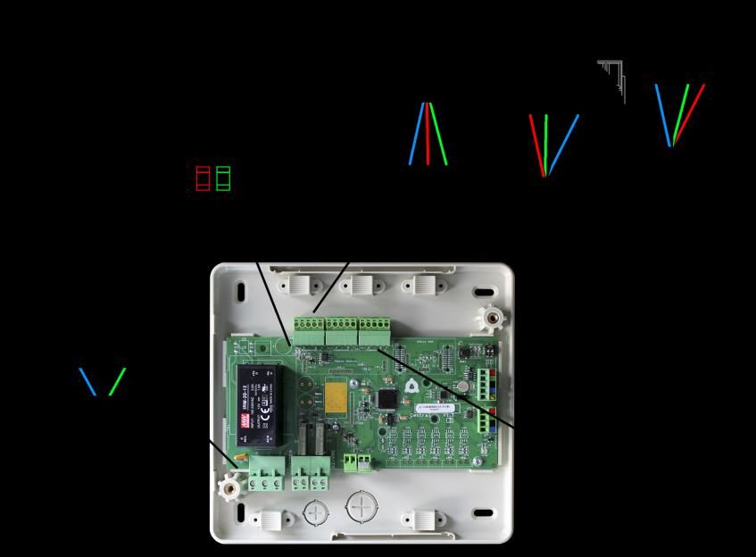
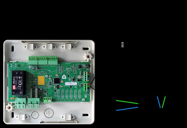
TABLE OF CONTENTS
Precautions and Environmental Policy ...............................................................................................................................................................................6
     Precautions ...............................................................................................................................................................................................................................6
     Environmental policy ...........................................................................................................................................................................................................6
System Elements ..........................................................................................................................................................................................................................7
     Control Board (AZVAFRxxxx) .............................................................................................................................................................................................7
     Wired/Wireless intelligent round damper (AZVAFDAMPERXX [C/R]) ...............................................................................................................7
     Wired/Wireless only radiant zone module (AZVAFZMRAD [C/R]) ......................................................................................................................7
     Wired/Wireless zone module with XXX communication (AZVAFZMXXX [C/R]) ...........................................................................................8
     Relay radiant heat control module (AZVAF5OUTPUTS) .........................................................................................................................................8
     Blueface principal controller (AZVAFBLUEFACEC)....................................................................................................................................................8
     Wired/Wireless Think controller (AZVAFTHINK [C/R]) .............................................................................................................................................9
     Wired/Wireless Lite controller (AZVAFLITE [C/R]) .....................................................................................................................................................9
     Communication gateway (AZVAFGTXXX) ...................................................................................................................................................................9
     0-10 V Fancoil control gateway (AZVAFGTF10) ...................................................................................................................................................... 10
     5-Relay Fancoil control gateway (AZVAFGTF5R) .................................................................................................................................................... 10
     Webserver Airzone cloud Ethernet/WiFi (AZVAFWSCLOUD [C/R]) ................................................................................................................. 10
     Bacnet integration gateway (AZVAFBACNETG) ...................................................................................................................................................... 11
     10 KOHM NTC thermistor (AZVAF10KPROBE) ......................................................................................................................................................... 11
     Additional 12 V power supply (AZVAFPOWER) ....................................................................................................................................................... 11
General requirements ............................................................................................................................................................................................................. 12
Introduction ................................................................................................................................................................................................................................ 13
System installation ................................................................................................................................................................................................................... 13
Assembly and connection ..................................................................................................................................................................................................... 15
     Control Board (AZVAFRxxxx) .......................................................................................................................................................................................... 15
           Assembly .......................................................................................................................................................................................................................... 15
           Connection ...................................................................................................................................................................................................................... 15
     Wired/Wireless intelligent round damper (AZVAFDAMPERXX [C/R]) ............................................................................................................ 18
           Connection ...................................................................................................................................................................................................................... 18
           Flow regulation .............................................................................................................................................................................................................. 19
     Wired/Wireless only radiant zone module (AZVAFZMRAD [C/R]) ................................................................................................................... 20
           Assembly .......................................................................................................................................................................................................................... 20
           Connection ...................................................................................................................................................................................................................... 20
     Wired/Wireless zone module with XXX communication (AZVAFZMXXX [C/R]) ........................................................................................ 21
           Assembly .......................................................................................................................................................................................................................... 21
           Connection ...................................................................................................................................................................................................................... 22
     Relay radiant heat control module (AZVAF5OUTPUTS) ...................................................................................................................................... 23
           Assembly .......................................................................................................................................................................................................................... 23
           Connection ...................................................................................................................................................................................................................... 24
     Wired thermostats (AZVAFBLUEFACEC / AZVAFTHINKC / AZVAFLITEC) ...................................................................................................... 24
           Assembly .......................................................................................................................................................................................................................... 24
            Connection ..................................................................................................................................................................................................................... 25
     Wireless thermostats (AZVAFTHINKR / AZVAFLITER)............................................................................................................................................ 25
           Assembly .......................................................................................................................................................................................................................... 25
           Changing batteries....................................................................................................................................................................................................... 25
                                                                                                                                                                                                                                              3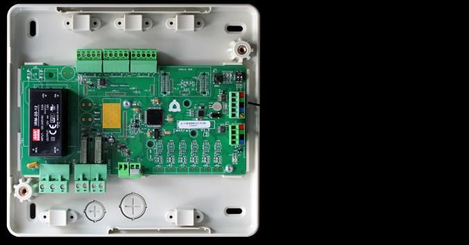
0-10 V Fancoil control gateway (AZVAFGTF10) ...................................................................................................................................................... 26
           Assembly .......................................................................................................................................................................................................................... 26
           Connection ...................................................................................................................................................................................................................... 27
     5-Relay Fancoil control gateway (AZVAFGTF5R) .................................................................................................................................................... 28
           Assembly .......................................................................................................................................................................................................................... 28
           Connection ...................................................................................................................................................................................................................... 28
     Ethernet/WiFi cloud Webserver (AZVAFWSCLOUD [C/R]) .................................................................................................................................. 30
           Assembly .......................................................................................................................................................................................................................... 30
           Connection ...................................................................................................................................................................................................................... 30
           Configuration ................................................................................................................................................................................................................. 31
     BACnet integration gateway (AZVAFBACNETG) ..................................................................................................................................................... 31
           Assembly .......................................................................................................................................................................................................................... 31
           Configuration ................................................................................................................................................................................................................. 31
Assembly and connection evaluation .............................................................................................................................................................................. 32
Secondary zones settings ...................................................................................................................................................................................................... 32
Initial Setup ................................................................................................................................................................................................................................. 32
     Blueface and Think thermostats ................................................................................................................................................................................... 32
     Lite thermostats .................................................................................................................................................................................................................. 35
           Lite thermostat reset ................................................................................................................................................................................................... 36
Initital configuration evaluation ......................................................................................................................................................................................... 36
User and zone settings ........................................................................................................................................................................................................... 37
     Blueface Thermostat .......................................................................................................................................................................................................... 37
           User Settings ................................................................................................................................................................................................................... 37
           Zone Settings ................................................................................................................................................................................................................. 37
     Think Thermostat ................................................................................................................................................................................................................ 38
           Setting Parameters ....................................................................................................................................................................................................... 38
Advanced settings .................................................................................................................................................................................................................... 41
     Advanced settings Blueface thermostat ................................................................................................................................................................ 41
           System settings .............................................................................................................................................................................................................. 41
           Zone settings .................................................................................................................................................................................................................. 43
     Advanced settings Think thermostat ...................................................................................................................................................................... 44
Self-diagnose .............................................................................................................................................................................................................................. 45
     Control board (AZVAFRxxxx) .......................................................................................................................................................................................... 45
     Wired/Wireless intelligent round damper and wired/wireless only radiant zone module (AZVAFDAMPERXXX [C/R] and
     AZVAFZMRAD [C/R]) .......................................................................................................................................................................................................... 46
     Wired/Wireless zone module with XXX communication (AZVAFZMXXX [C/R]) ........................................................................................ 46
     Relay radiant heat control module (AZVAF5OUTPUTS) ...................................................................................................................................... 47
     Blueface and think thermostats (AZVAFBLUEFACEC / AZVAFTHINK [C/R]) ................................................................................................. 48
           Blueface and Think Thermostat Warnings .......................................................................................................................................................... 48
           Blueface and Think Thermostats errors ............................................................................................................................................................... 48
     Lite Thermostats (AZVAFLITE [C/R]) ............................................................................................................................................................................. 55
     Communication gateways (AZVAFGTXXX)............................................................................................................................................................... 58
     0-10 V Fancoil controlgateway (AZVAFGTF10) ....................................................................................................................................................... 58
     5-Relay Fancoil Control gateway (AZVAFGTF5R) ................................................................................................................................................... 59
     Ethernet/WiFi Cloud Webserver (AZVAFWSCLOUD [C/R]) ................................................................................................................................. 59
     Bacnet Integration Gateway (AZVAFBACNETG) ..................................................................................................................................................... 60
                                                                                                                                                                                                      4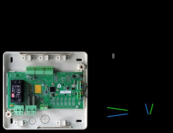
Navigation Trees ....................................................................................................................................................................................................................... 61
     Blueface Thermostat Navigation Tree ........................................................................................................................................................................ 61
     Think Thermostat Navigation Tree .............................................................................................................................................................................. 62

                                                                                                                                                                                                                                        5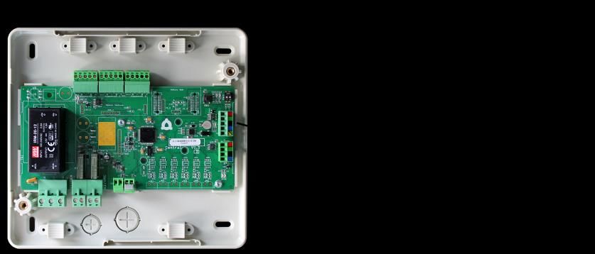
PRECAUTIONS AND ENVIRONMENTAL POLICY
PRECAUTIONS
For your security, and to protect the devices, follow these instructions:
    •    Do not manipulate the system with wet or damp hands.
    •    Disconnect the power supply before making any connections.
    •   Take care not to cause a short circuit in any of the system connections.

ENVIRONMENTAL POLICY
                                 Do not dispose of this equipment in the household waste. Electrical and electronic
                                 equipment contain substances that may damage the environment if they are not handled
                                 appropriately. The symbol of a crossed-out waste bin indicates that electrical equipment
                                 should be collected separately from other urban waste. For correct environmental
                                 management, it must be taken to the collection centers provided for this purpose, at the end
                                 of its useful life.
                                 The equipment components may be recycled. Act in accordance with current regulations on
                                 environmental protection.
                                 If you replace it with other equipment, you must return it to the distributor or take it to a
                                 specialized collection center.
                                 Those breaking the law or by-laws will be subject to such fines and measures as are laid down
                                 in environmental protection legislation.

                                                                                                                                 6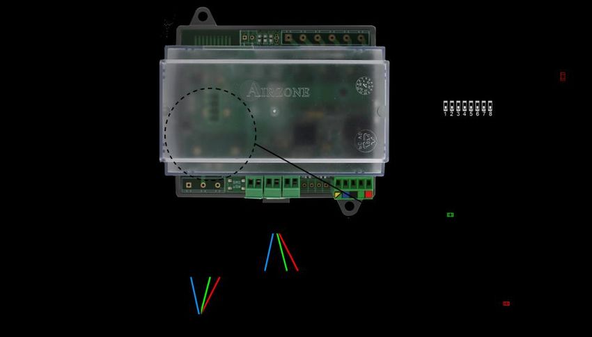
SYSTEM ELEMENTS
CONTROL BOARD (AZVAFRXXXX)
Electronic board with a communication gateway (see section Communication Gateway AZVAFGTxxx for more information),
which manages all wired and wireless devices in the system. Externally powered at 110 / 230 VAC. Wall mounted.
Functionalities:
    •    Controls the status of the thermostats (up to 10 zones).
    •    Controls the proportionality and the minimum air supply of the dampers.
    •    Control of auxiliary heat (up to two stages).
    •    Control gateway management.
    •    Communication with units of integral control of the installation.
    •    Communications with other external control systems through integration bus.

WIRED/WIRELESS INTELLIGENT ROUND DAMPER (AZVAFDAMPERXX [C/R])
Damper with actuator
Damper with actuator of 6, 8, 10, 12 or 14 inch diameter. Powered with 12 VDC by the zone module.

Zone module
Local control module for controlling damper. Wired/wireless
communication with zone thermostat. Powered through system
Airzone connection bus.
Functionalities:
•   Input for detection of open windows.
•   Input for detection of presence.
•   Probe input.
•   Remote probe function and distributed probe function.

WIRED/WIRELESS ONLY RADIANT ZONE MODULE (AZVAFZMRAD [C/R])
Local control module for controlling radiant elements.
Wired/wireless communication with zone thermostat. Powered
through system Airzone connection bus.
Functionalities:
•   Input for detection of open windows.
•   Input for detection of presence.
•   Probe input.
•   Remote probe function and distributed probe function.

                                                                             AZVAFZMRADC            AZVAFZMRADR

                                                                                                                  7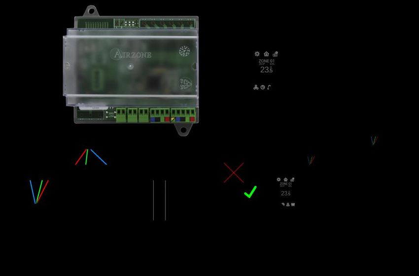
WIRED/WIRELESS ZONE MODULE WITH XXX COMMUNICATION (AZVAFZMXXX [C/R])
Module for controlling direct expansion individual units through communication gateway (see section Communication
Gateway AZVAFGTxxx for more information). Wired/wireless communications with zone thermostat. Powered through system
Airzone connection bus. Mounted on DIN rail or on wall.
Functionalities:
    •    Input for detection of open windows.
    •    Input for detection of presence.
    •    Probe input.
    •    Remote probe function and distributed probe
         function.

                                                                       AZVAFZMxxxC                   AZVAFZMxxxR

RELAY RADIANT HEAT CONTROL MODULE (AZVAF5OUTPUTS)
Control module of radiant heat for heating stages. Communications via Airzone connection
bus of control board. Powered by control board. Mounted on DIN rail.
Functionalities:
    •    Control up to 5 zones of heating elements by means of free-voltage relays.
    •    Demand Relay of Pump.
    •    Demand Relay of Boiler.
    •    Identified by means of a micro-switch.

BLUEFACE PRINCIPAL CONTROLLER (AZVAFBLUEFACEC)
Color graphic interface with capacitive screen for controlling zones in Airzone systems. Powered by zone module. Finished in
steel and glass.
Functionalities:
    •    Available in English, French and Spanish.
    •    Control of temperature, operation mode (main thermostat), user mode (main
         thermostat) and system speed or airflow (depends on the type of installation).
    •    Room temperature and relative humidity measurement of the zone.
    •    Configuration stages control (air, radiant or air+radiant).
    •    Timer function.
    •    Temperature, user mode and on/off time schedules.
    •    Remote access to other zones of the system.
    •    Weather forecast (optional).

                                                                                                                          8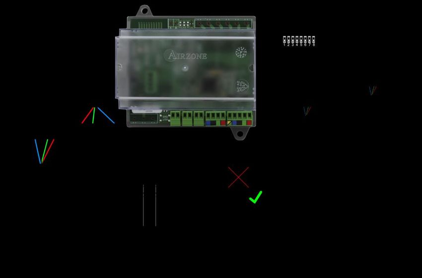
WIRED/WIRELESS THINK CONTROLLER (AZVAFTHINK [C/R])
Graphic interface with low-energy e-ink screen and capacitive buttons for controlling zones in Airzone systems. Wired/wireless
communications. Finished in steel and glass. Powered by zone module (wired) or by battery button CR2450 (wireless).
Functionalities:
    •    Available in English, French and Spanish.
    •    Control of temperature, operation mode (main thermostat), user mode (main
         thermostat) and system speed or airflow (depends on the type of installation).
    •    Room temperature and relative humidity measurement of the zone.
    •    Configuration stages control (air, radiant or air+radiant).
    •    Timer function.
    •    Weather forecast (optional).

WIRED/WIRELESS LITE CONTROLLER (AZVAFLITE [C/R])
Thermostat with capacitive buttons for controlling the temperature of the zones in Airzone systems. Wired/wireless
communication. Powered by zone module (wired) or by battery button CR2450 (wireless).
Functionalities:
    •    On/off of the zone.
    •    Set-point temperature control (accuracy: ±                                   ).
    •    Room temperature and relative humidity reading.

COMMUNICATION GATEWAY (AZVAFGT XXX)
Element that integrates the functioning of the AC units and Airzone zoning systems, enhancing the performance of the
installation:
    •    ON/OFF depending on the number of zones in demand.
    •    Automatic mode changeover (Auto, Cooling, Heating or Dry) from main
         thermostat.
    •    Automatic fan speed selection based on the number of zones on demand.
    •    Set-point temperature adjustment based on the set-point temperatures of the
         zone thermostats of the system.

                                                                                                                            9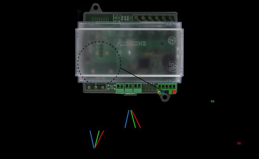
0-10 V FANCOIL CONTROL GATEWAY (AZVAFGTF10)
Control gateway of air-to-water zoning units. Fan control through 0-10 V output and opening-
closing electrovalves. Compatible with 2-pipe and 4-pipe installations. Externally powered at
110/230 Vac. Mounted on DIN rail or on wall.
Functionalities:
    •    Two relays for electrovalve control by demand.
    •    0-10 V output for fan control.
    •    Automatic speed control based on the zones on demand.

5-RELAY FANCOIL CONTROL GATEWAY (AZVAFGTF5R)
Control gateway for air-to-water air conditioners. Control up to three fan-speeds and the
opening and closing of valves. Compatible with 2 pipes or 4 pipes air conditioners.
Externally power supplied at 110/230. Mounted on DIN rail or on wall.
Functionalities:
    •    Two electro-valve control relays for demand.
    •    Three control relays for fan-speed selection.
    •    Automatic speed selection according to the number of zones on demand.

WEBSERVER AIRZONE CLOUD ETHERNET/WIFI (AZVAFWSCLOUD [C/R])
Webserver for controlling Airzone systems through Airzone Cloud platform. Accessible through browser or App (available for
IOS and Android). Connected to router via Ethernet (AZVAFWSCLOUDC) or WiFi (AZVAFWSCLOUDR). Powered through
automation bus.
Functionalities:
    •    Control of up to 32 systems.
    •    Configuration and control of zone parameters (Room and set-point temp., operating mode, etc.) and system
         parameters via Airzone Cloud.
    •    Temperature and operating mode time schedules.
    •    Multi-user and multi-session.
    •    External control through Airzone Cloud platform.
    •    Remote updates of the Webserver firmware and the systems connected to it.
    •    Remote error detection and error resolution.

                         AZVAFWSCLOUDC                                              AZVAFWSCLOUDR

                                                                                                                       10
BACNET INTEGRATION GATEWAY (AZVAFBACNETG)
Integration gateway for controlling Airzone installations through BACnet platform. Connected to router via Ethernet. Power
supplied through the control board automation bus.
Functionalities:
• One BACnet gateway per system.
• Status of window contact and presence contact of each zone.
• Status of the radiant stage of each zone.
• On/Off of each zone.
• Set-point temperature control of each zone.
• Operating mode status.
• State and Fancoil fan speed.
10 KOHM NTC THERMISTOR (AZVAF10KPROBE)
Temperature probe in metal sheath.
Functionalities:
• Configurable for remote or distributed sensing.
• Protection probe for air supply.
ADDITIONAL 12 V POWER SUPPLY (AZVAFPOWER)
External power supply for Airzone system. DIN rail mounted. 110/230 Vac power supply:
• Power supply for more than 6 zone modules via Blueface or 10 zone modules without Blueface. These values
can be altered depending on the separation distance among them.
11GENERAL REQUIREMENTS
Strictly follow the directions outlined in this manual:
• This system must be installed by a qualified technician.
• Make all the connections with total absence of power.
• Set and connect the elements in accordance with the electronic regulations in force.
• In order to connect the elements of the system, use the cable: shielded twisted cable formed by 4 wires
(AWG 20 4 wired).
• Do not connect the "-" pole in the "+" terminal. It may damage the device.
• For elements externally powered at 110/230 Vac, for the communications, it is only necessary to connect the poles "A"
and "B" of the bus. Connecting the "+" and " -" power poles is not recommended.
• To connect the actuators to the actuator outputs, use a 2-core section cable (0.75 mm2).
• Follow the color code for all the elements of the system.
• Do not place the system bus close to lines of force, fluorescent lights, motors, etc. It might cause interference on the
communications.
• It is recommended to label all the actuator outputs in order to facilitate their subsequent identification.
• Follow these recommendations to locate the thermostats:
Important: According to the current local and national regulations, it is mandatory to add a switch (or other element to
disconnect the system) to the external supply wiring so that a constant separation between poles is guaranteed. The system
will restart automatically if the supply is eventually turned off.
12INTRODUCTION
Airzone systems enable the management of Main and Zone interfaces. Main thermostats enable mode management or user
mode and fan speed of the system.
- Blueface Main: Mode, User mode icons shown in white color.
- Blueface Zone: Mode, User mode and Speed icons shown in gray color.
- Think Main: Accessing the settings menu, Operation mode and User mode are available.
- Think Zone: Accessing the settings menu, Operation mode and User mode are unavailable.
SYSTEM INSTALLATION
Before performing the Airzone system installation, check:
•
the Airzone system.
• In direct expansion unit systems, the indoor unit wired thermostat has been installed.
Important: For installations with radiant surfaces only, it is recommended the installation of buffer tanks.
In order to install properly your Airzone system, follow these steps:
Locate all the elements and perform the connection (See section Assembly and Connection).
- Zone and Control Modules connection with the Airzone VAF Control board. Connect the zone modules of the
system to any of the 3 Airzone connection bus terminals. Use the proper cable: shielded twisted pair 4 wired:
2x0.22 mm2 + 2x0.5mm2 (AWG 20 4 wired). They must be connected by bus. For added security, secure the wires using
the turrets.
IMPORTANT: The maximum number of zone modules connected without their own power supply to the Airzone VAF
control Board is: 6 zone modules connected to Blueface thermostats or 10 zone modules connected to Think or Lite
thermostats. To add more zone modules, it is necessary to install the supplementary power supply unit (Airzone VAF
additional 12V power supply). Every supplementary power supply unit is enough for 6 or 10 modules as stated before.
- Connecting the thermostats. Connect each thermostat to the terminal corresponding to its zone module. Use the
proper cable: shielded twisted pair 4 wired: 2x0.22 mm2 + 2x0.5mm2 (AWG 20 4 wired). In case of Wireless thermostat,
check it has the battery on.
- Configuration and connection of the relay radiant heat control module. If you have a relay radiant heat control
module, configure the SW2 microswitch depending on the zones to control. Once configured, perform the connection
with the radiant elements to control per each relay output of the module.
- Connection to the ducted unit (see section Gateway Connection). It is recommended to install the thermostat of the
unit. For the connection of DIN rail gateways to the control board, use the proper cable: shielded twisted pair 2 wired:
2x0.22 mm2 (AWG 24 2 wired).
- Connection of the zone modules with the elements/systems to control (Fancoil, Split, etc.). (See section zone
module connection).
13- Webserver Cloud connection or BACnet integration gateway. Connect your Webserver Cloud or BACnet Gateway
to the automation bus of the Control Board (follow the steps shown on the Assembly section).
All Airzone systems must be connected to internet to offer technical support.
It is only necessary to connect one Webserver Cloud per installation (control of up to 32
systems), for BACnet integration gateway, one per system.
- Auxiliary Heat and other peripherals. If your system includes auxiliary heat, connect the auxiliary heat relays of the
VAF Control board to the elements to control.
- Powering the system. Use the power input to power at 110 / 230 Vac the control board and any others control
elements that require it. To do that, use a 3x1,5 mm² cable (AWG 15 3 wired). For added security, secure the wires
using the turret.
Check all the assembly and the connection are correct (see section Assembly and connection evaluation).
Configure the system.
- Configure the secondary modules to associate them to a main thermostat (see section Secondary zones settings).
- Configure all the thermostats (see sections Initial setup and Advanced settings).
Check the correct operation of the system (See Initial Configuration Evaluation).
Access all our technical documents and the self-diagnosis section, check the most FAQs,
certificates, watch our videos and read our declaration of conformity at:
myzone.airzoneusa.com
to download, complete and print the Commissioning document available on
myzone.airzoneusa.com to place it together with your installation.
14ASSEMBLY AND CONNECTION
CONTROL BOARD (AZVAFRXXXX)
Assembly
The production control board is supplied in a box to be screwed to the wall (Fig. 1). It should
be placed and mounted in accordance with the current electrotechnical regulations.
For the mounting of the control board, follow the following steps:
• Locate the control board close to the unit to be controlled.
• Unscrew the cover securing the back part to the wall.
Fig. 1
• Make all the connections and screw the cover again.
Connection
N Description
Airzone Connection Bus
SW1
Automation bus
AC unit bus
Alarm input (normally closed)
Protection temperature probe
Auxiliary heat 2nd Stage output
Auxiliary heat 1st Stage output
Power supply
Fig. 2
Airzone Connection Bus connectors
The Airzone Connection Bus allows you to connect all the internal components that are independent from the main board to
control up to 10 zones. These are the gateways that can be connected:
- Wired/Wireless intelligent round damper (AZVAFDAMPERxxx [C/R]).
- Wired/Wireless only radiant zone module (AZVAFZMRAD [C/R]).
- Wired/Wireless zone module with XXX communication (AZVAFZMxxx [C/R]).
- Relay radiant heat control module (AZVAF5OUTPUTS).
It has 3 5-pin terminals to connect the Airzone Connection Bus. Use the proper cable: shielded
twisted pair 4 wired: 2x0.22 mm2 + 2x0.5mm2 (AWG 20 4 wired). They must be connected by
bus. Attach the wires with the terminal screws following the color code (Fig. 3). For added security,
secure the wires using the turrets (Fig. 4).
Fig. 3
Note: For elements externally powered at 110/230 Vac, it is only necessary to connect the poles
.
15Fig. 4
SW1
The control board can also connect to Airzone wireless elements. These elements are associated by
opening the wireless association module of the Control board. Press on SW1 and wait for the LED 19 to
remain red (Fig. 5). The wireless association module will be open for 15 minutes.
System reset: If you want to return to factory values, press and hold on SW1 (Fig. 5) until LED D19 stops
blinking. Wait 60 seconds until the system restarts before connecting again. Fig. 5
Automation bus connector
The automation bus allows you to interconnect multiple systems in order to control them through Airzone control peripherals
or to integrate them into a superior control network. The elements to connect to this bus are:
- Ethernet/WiFi Cloud Webserver (AZVAFWSCLOUD [C/R]).
- BACnet Integration Gateway (AZVAFBACNETG).
All Airzone systems must be connected to internet to offer technical support.
It is only necessary to connect one Webserver Cloud per installation (control of up to 32 systems), for
BACnet integration gateway, one per system.
AC unit bus connector
The AC unit bus allows you to connect different control gateway to the AC unit. The elements to connect are:
- Communication gateways (AZVAFGT xxx).
- 0-10 V Fancoil control gateway (AZVAFGTF10).
- 5 relays Fancoil control gateway (AZVAFGTF5R).
It has a 4-pin terminal to connect the AC unit bus. Use the proper cable: shielded twisted pair
2 wired: 2x0.22 mm2 (AWG 24 2 wired). They must be point-to-point connected. Attach the
wires with the terminal screws following the color code (Fig. 6).
Fig. 6
Alarm input
This input closes all the dampers and imposes Stop mode when there is an alert. This input is configured as normally closed.
For proper operation of the system, this contact is supplied with a bonding jumper.
16Protection temperature probe connector
It measures the outdoor temperature through an external probe. We recommend the use of this probe when using
electromechanical units or NON-Inverter units (when it is necessary to control the return temperature of the units).
Auxiliary heat outputs
The system includes auxiliary heat, connect the auxiliary heat relays of the VAF Control board to the elements to control. Control
relay specs are Imax: from 1 A to 24-48 V, voltage-free. To control elements of a greater power, it is recommended to use
contactors in accordance with the power required.
Power supply connector
This connector powers the control board and all the elements connected to it. Externally powered
at 110/230 Vac. It is connected through a 3-pin terminal. Use a 3x1,5 mm² (AWG 15 3 wired) cable.
Attach the wires with the terminal screws following the color code (Fig. 7). For added security,
secure the wires using the turret (Fig. 8). Fig. 7
Fig.8
Important: According to the current local and national regulations, it is mandatory to add a switch (or other element to
disconnect the system) to the external supply wiring so that a constant separation between poles is guaranteed. The system
will restart automatically if the supply is eventually turned off.
Remember: Once all the connections are made, make sure you replace the cover properly (Fig. 9).
Fig. 9
17WIRED/WIRELESS INTELLIGENT ROUND DAMPER (AZVAFDAMPERXX [C/R])
Connection
N Meaning
Motorized element connector
Probe connector
Airzone Connection Bus
Thermostat connection (Only AZVAFDAMPERxxC)
Presence contact
Window contact
Note: Use a shielded twisted pair to connect the window contact.
The Intelligent round damper is a device that is connected to the Airzone Connection Bus of the control board (Fig. 11).
Fig. 11
It has a 5-pin terminal to connect it to the Airzone Connection Bus of the main board. Use the proper
cable: shielded twisted pair 4 wired: 2x0.22 mm2 + 2x0.5mm2 (AWG 20 4 wired). Attach the wires with the
Fig. 12
terminal screws following the color code (Fig. 12).
It has a 4-pin terminal to connect the thermostat. Use the proper cable: shielded twisted pair 4 wired:
2x0.22 mm2 + 2x0.5mm2 (AWG 20 4 wired). Attach the wires with the terminal screws following the color
code (Fig. 13).
Remember: The maximum separation between the module and the thermostat is 40 meters. Fig. 13
The zoning module allows you to connect a probe (AZVAF10KPROBE) for remote or distributed temperature reading,
depending on how the module is configured:
• Remote probe: This function allows you to read the room temperature even if you are not where the thermostat is
located. Connect the probe and configure the module as main module (connected thermostat). The state and the set-
point temperature are set via thermostat while the probe reads the room temperature.
• Distributed probe: This function allows you to control a subordinate zone with room temperature reading
independent from the main zone. Connect the probe and configure the module as secondary (disconnected
thermostat). The state and the set-point temperature are set via thermostat while the probe reads the room
temperature.
The module has several inputs to control based on the occupancy or if there are open windows.
18• Control by occupancy: When the occupancy sensor connected to the module indicates that the zone is unoccupied,
the system waits for 5 minutes to confirm it is actually empty. After this period of time, the zone is set to Timer Mode
and it turns off after 90 minutes.
• Control by open window: When the open window sensor connected to the module indicates that a window is open
for more than 60 seconds, the control element (actuator/relay) associated with that module closes.
The activation and configuration of these inputs are available in the zone settings menu of the thermostat (See Advanced
Settings).
Flow regulation
The intelligent motorized dampers include a control system that allows to manually set the maximum and minimum opening
of each damper.
Flow adjustment (REG)
The damper offers a maximum opening adjustment which balances the airflow of each damper based on the real needs of the
installation. By default, the damper is set at the I position. To adjust it, follow the steps:
1. Turn on and generate demand in all zones to open all the dampers.
2. Turn off the zone/damper to be adjusted.
3. Adjust the maximum opening you want with the REG lever (I/II/III/IV).
4. Turn on the zone and check the flow is correct.
Minimum Air Setting (A-M)
The damper enables the adjustment of a minimum opening. By default, . To adjust it, follow
the steps:
1. Turn on and generate demand in all zones to open all the dampers.
2. Adjust the minimum opening you want with the M-A lever (a/b/c/d).
3. Turn on the zone and check the minimum air flow is correct.
A-M REG
19WIRED/WIRELESS ONLY RADIANT ZONE MODULE (AZVAFZMRAD [C/R])
N Meaning
Probe connector
Airzone connection bus
Thermostat connection (Only AZVAFZMRADC)
Presence contact
Window contact
Note: Use a shielded twisted pair to connect the window contact.
Fig. 14
Assembly
This module is designed to control radiant elements. It is required to have one module per radiant element of the system.
Use the guideway to fix it to the motorized element to be controlled (Fig. 15).
Fig. 15
Connection
The Only Radiant Zone Module is a device that is connected to the Airzone connection bus of the control board (Fig. 16).
Fig. 16
It has a 5-pin terminal to connect it to the Airzone Connection Bus of the main board. Use the proper
cable: shielded twisted pair 4 wired: 2x0.22 mm2 + 2x0.5mm2 (AWG 20 4 wired). Attach the wires with the
terminal screws following the color code (Fig. 17).
Fig. 17
20It has a 4-pin terminal to connect the thermostat. Use the proper cable: shielded twisted pair 4 wired:
2x0.22 mm2 + 2x0.5mm2 (AWG 20 4 wired). Attach the wires with the terminal screws following the color
code (Fig. 18).
Remember: The maximum separation between the module and the thermostat is 40 meters. Fig. 18
The zoning module allows you to connect a probe (AZVAF10KPROBE) for remote or distributed temperature reading,
depending on how the module is configured:
• Remote probe: This function allows you to read the room temperature even if you are not where the thermostat is
located. Connect the probe and configure the module as main module (connected thermostat). The state and the set-
point temperature are set via thermostat while the probe reads the room temperature.
• Distributed probe: This function allows you to control a subordinate zone with room temperature reading
independent from the main zone. Connect the probe and configure the module as secondary (disconnected
thermostat). The state and the set-point temperature are set via thermostat while the probe reads the room
temperature.
The module has several inputs to control based on the occupancy or if there are open windows.
• Control by occupancy: When the occupancy sensor connected to the module indicates that the zone is unoccupied,
the system waits for 5 minutes to confirm it is actually empty. After this period of time, the zone is set to Timer Mode
and it turns off after 90 minutes.
• Control by open window: When the open window sensor connected to the module indicates that a window is open
for more than 60 seconds, the control element (actuator/relay) associated with that module closes.
The activation and configuration of these inputs are available in the zone settings menu of the thermostat (see Advanced
Configuration).
WIRED/WIRELESS ZONE MODULE WITH XXX COMMUNICATION (AZVAFZM XXX [C/R])
N Description
Probe Input
Window contact
Presence contact
Thermostat Connection (Only AZVAFZMxxxC)
Airzone Connection Bus
Note: Use a shielded twisted pair to connect the window contact.
Fig. 19
Assembly
The module is mounted on DIN rail (Fig. 20) or on wall (Fig. 21). It must be placed and mounted in accordance with the current
electrotechnical regulations.
21Fig. 20 Fig. 21
Note: To remove the module on DIN rail, pull the tab down to release it.
Connection
The gateway module is a device that is connected to the Airzone connection bus of the control board (Fig. 34).
Fig. 22
It has a 5-pin terminal to connect it to the Airzone Connection Bus of the main board. Use the proper
cable: shielded twisted pair 4 wired: 2x0.22 mm2 + 2x0.5mm2 (AWG 20 4 wired). Attach the wires with
the terminal screws following the color code (Fig. 23).
Fig. 23
It has a 4-pin terminal to connect the thermostat. Use the proper cable: shielded twisted pair 4 wired:
2x0.22 mm2 + 2x0.5mm2 (AWG 20 4 wired). Attach the wires with the terminal screws following the
color code (Fig. 24).
Remember: The maximum separation between the module and the thermostat is 40 meters. Fig. 24
The module allows to connect a probe (AZVAF10KPROBE) for remote or distributed temperature reading, depending on how
the module is configured:
• Remote probe: This function allows you to read the room temperature even if you are not where the thermostat is
located. Connect the probe and configure the module as main module (connected thermostat). The state and the set-
point temperature are set via thermostat while the probe reads the room temperature.
• Distributed probe: This function allows you to control a subordinate zone with room temperature reading
independent from the main zone. Connect the probe and configure the module as secondary (disconnected
thermostat). The state and the set-point temperature are set via thermostat while the probe reads the room
temperature.
The module has several inputs to control based on the occupancy or if there are open windows.
22• Control by occupancy: When the occupancy sensor connected to the module indicates that the zone is unoccupied,
the system waits for 5 minutes to confirm it is empty. After this period of time, the zone is set to Timer Mode and it
turns off after 90 minutes.
• Control by open window: When the open window sensor connected to the module indicates that a window is open
for more than 60 seconds, the control element (actuator/relay) associated with that module closes.
The activation and configuration of these inputs are available in the zone settings menu of the thermostat (see Advanced
settings, Zone settings).
RELAY RADIANT HEAT CONTROL MODULE (AZVAF5OUTPUTS)
N Description
Zone relay
Pump control relay
Boiler control relay
SW2
Airzone connection bus
Fig. 25
Assembly
The module is mounted on DIN rail (Fig. 26) or on wall (Fig. 27). It must be placed and mounted in accordance with the current
electrotechnical regulations.
Fig. 26 Fig. 27
Note: To remove the module on DIN rail, pull the tab down to release it.
23Connection
The Relay Radiant Heat Control Module is a device that is connected to the Airzone Connection Bus of the control board
(Fig. 28).
Fig. 28
Control relay specs: 24/48 Vac (voltage-free). To control elements of a greater power, it is recommended the use of contactors
in accordance with the power required. Remember to connect the neutral connector directly from the circuit to the element to
be controlled.
The SW2 microswitch configuration (zone ID) is as follows:
SW2
Zones 1 - 5 Zones 6-10
Example: The relay to control a radiant element of a module with address 6 is the R1 of the Relay Radiant Heat Control Module
with the address set for the zones 6-10.
It has a 4-pin terminal to connect it to the AC unit bus of the main board. Use the proper cable:
shielded twisted pair 4 wired: 2x0.22 mm2 + 2x0.5mm2 (AWG 20 4 wired). Attach the wires with
the terminal screws following the color code (Fig. 29).
Fig. 29
WIRED THERMOSTATS (AZVAFBLUEFACEC / AZVAFTHINKC / AZVAFLITEC)
Assembly
Airzone thermostats are mounted on the wall through a support. It is recommended not to locate it more than 40 meters away
from the control board. To fix it to the wall, follow these steps (Fig. 30):
• Separate the back part of the thermostat from the wall support and make all the
connections.
• Fix the back part of the thermostat to the wall.
• Place the display on the support once it is fixed.
Fig. 30
24Connection
Airzone thermostats are connected to the zone module to be controlled. Attach the wires with the
terminal screws following the color code (Fig. 31).
Important: Use the provided tool to press in the locking tabs (Fig. 32). Fig. 31
Fig. 32
WIRELESS THERMOSTATS (AZVAFTHINKR / AZVAFLITER)
Assembly
Wireless thermostats are mounted on the wall through a support. It is recommended not to locate it more than 40 meters away
from the control board.
To fix it to the wall, follow these steps (Fig. 33):
• Separate the back part of the thermostat from the wall support and insert the
CR2450 button battery.
• Fix the back part of the thermostat to the wall.
• Place the display on the support once it is fixed.
Fig. 33
Changing batteries
When a Think thermostat is running out of battery, it displays this icon on the screensaver (Fig. 34). In the case of the
wireless Lite thermostats, a warning message will be displayed on the Blueface. In order to know the zone of the Lite
thermostat(s) running out of battery press on the warning icon (Fig. 35).
Fig. 34 Fig. 35
To replace the battery, separate the thermostat from its support and replace the battery (CR2450) (Fig. 36).
Note: For Lite thermostats, the low battery warning will disappear after about 5 minutes from the battery replacement.
25Fig. 36
Important: We recommend using of top-brand batteries. Using low-quality batteries may reduce the duration of use.
Remember to deposit the old battery into an appropriate recycling point.
0-10 V FANCOIL CONTROL GATEWAY (AZVAFGTF10)
Meaning
Power supply
AC unit bus
OUT 1 Cooling air demand
OUT 2 Heating air demand
OUT 3 Fan demand
Fan speed
Fig. 37
Assembly
The 0-10 V control gateway is mounted on DIN rail (Fig. 38) or on wall (Fig. 39). This module is externally powered at 110/230
Vac. It is should be placed and mounted in accordance with the current electrotechnical regulations.
Fig. 38 Fig. 39
Note: To remove the module on DIN rail, pull the tab down to release it.
26Connection
The 0-10 V control gateway is connected to the AC unit bus of the main board (Fig. 40 and 41).
Wiring diagram, 2-pipe installation
Fig.40
Wiring diagram, 4-pipe installation
Fig. 41
Control relay specs: Imax = 10 A at 110/230 Vac, voltage-free. Note that to control elements with a greater power, it is
recommended to use contactors in accordance with the power required.
It has a 5-pin terminal to connect it to the AC unit bus of the main board. Use the proper cable: shielded
twisted pair 2 wired: 2x0.22 mm2 (AWG 24 2 wired). Attach the wires with the terminal screws
following the color code (Fig. 42). Fig. 42
It is connected to the module through a 3-pin terminal. To do that, use a 3x1.5 mm² (AWG 15 3 wired)
cable. Attach the wires with the terminal screws following the color code (Fig. 43).
Fig. 43
Important: According to the current local and national regulations, it is mandatory to add a switch (or
other element to disconnect the system) to the external supply wiring so that a constant separation between poles is
guaranteed. The system will restart automatically if the supply is eventually turned off.
275-RELAY FANCOIL CONTROL GATEWAY (AZVAFGTF5R)
N Description
Power supply
AC unit bus
Y-O Cooling air demand
V1-O Speed 1
V2-O Speed 2
V3-O Speed 3
W-O Heating air demand
Status LEDs
Fig. 44
Assembly
The 5-Relay Fancoil control gateway is mounted on DIN rail (Fig. 45) or on wall (Fig. 46). This module is externally powered at
110/230 Vac. It is should be placed and mounted in accordance with the current electrotechnical regulations.
Fig. 45 Fig. 46
Note: To remove the module on DIN rail, pull the tab down to release it.
Connection
The 5-Relay Fancoil control gateway is connected to the AC unit bus of the main board (Fig. 47 and 48).
Wiring diagram, 2-pipe installation
Fig.47
28Wiring diagram, 4-pipe installation
Fig. 48
Control relay specs: Imax = 10 A at 110/230 Vac, voltage-free. Note that to control elements with a greater power, it is
recommended to use contactors in accordance with the power required.
It has a 5-pin terminal to connect it to the AC unit bus of the main board. Use the proper cable: shielded
twisted pair 2 wired: 2x0.22 mm2 (AWG 24 2 wired). Attach the wires with the terminal screws
following the color code (Fig. 49). Fig. 49
It is connected to the module through a 3-pin terminal. To do that, use a 3x1.5 mm² (AWG 15 3 wired)
cable. Attach the wires with the terminal screws following the color code (Fig. 50).
Fig. 50
Important: According to the current local and national regulations, it is mandatory to add a switch (or
other element to disconnect the system) to the external supply wiring so that a constant separation between poles is
guaranteed. The system will restart automatically if the supply is eventually turned off.
29You can also read