FIBER BRAGG GRATING (FBG) SENSORS IN A HIGH-SCATTERING OPTICAL FIBER DOPED WITH MGO NANOPARTICLES FOR POLARIZATION-DEPENDENT TEMPERATURE SENSING ...
←
→
Page content transcription
If your browser does not render page correctly, please read the page content below
applied
           sciences
Article
Fiber Bragg Grating (FBG) Sensors in a
High-Scattering Optical Fiber Doped with MgO
Nanoparticles for Polarization-Dependent
Temperature Sensing
Carlo Molardi 1 , Tiago Paixão 2 , Aidana Beisenova 1 , Rui Min 3,4 , Paulo Antunes 2 ,
Carlos Marques 2 , Wilfried Blanc 5 and Daniele Tosi 1,6, *
 1    School of Engineering, Nazarbayev University, 53 Kabanbay Batyr, Astana 010000, Kazakhstan
 2    Physics Department & I3N, University of Aveiro, 3810-193 Aveiro, Portugal
 3    Intelligent Manufacturing Faculty, Wuyi University, Jiangmen, China
 4    ITEAM Research Institute, Universitat Politècnica de València, 46022 València, Spain
 5    INPHYNI–CNRS UMR 7010, Université Côte d’Azur, Parc Valrose, 06108 Nice, France
 6    Laboratory of Biosensors and Bioinstruments, National Laboratory Astana, 53 Kabanbay Batyr,
      Astana 010000, Kazakhstan
 *    Correspondence: daniele.tosi@nu.edu.kz

 Received: 3 July 2019; Accepted: 30 July 2019; Published: 1 August 2019

 Featured Application: Inscription and interrogation of fiber Bragg gratings into MgO
 nanoparticle-doped fiber for optical fiber distributed and multiplexed sensing.

 Abstract: The characterization of Fiber Bragg Grating (FBG) sensors on a high-scattering fiber, having
 the core doped with MgO nanoparticles for polarization-dependent temperature sensing is reported.
 The fiber has a scattering level 37.2 dB higher than a single-mode fiber. FBGs have been inscribed by
 mean of a near-infrared femtosecond laser and a phase mask, with Bragg wavelength around 1552 nm.
 The characterization shows a thermal sensitivity of 11.45 pm/◦ C. A polarization-selective thermal
 behavior has been obtained, with sensitivity of 11.53 pm/◦ C for the perpendicular polarization (S)
 and 11.08 pm/◦ C for the parallel polarization (P), thus having 4.0% different sensitivity between
 the two polarizations. The results show the inscription of high-reflectivity FBGs onto a fiber core
 doped with nanoparticles, with the possibility of having reflectors into a fiber with tailored Rayleigh
 scattering properties.

 Keywords: Fiber Bragg Grating (FBG); Rayleigh scattering; FBG sensor; enhanced backscattering
 fiber; polarization-sensitive device

1. Introduction
     A Fiber Bragg Grating (FBG) is a periodic modulation of the refractive index within the core of an
optical fiber [1], which results in a wavelength-selective resonant behavior that resonates at the so-called
Bragg wavelength [2]. The spectrum of an FBG results in a narrow bandwidth of reflected waves,
while the remainder of the spectrum is transmitted through the grating. The FBG, as well described
in [1,2], implements the Bragg resonant condition within an optical fiber, and results in a compact
device that finds broad applications in telecommunications and sensing. In fiber optics, FBGs are
extremely important as they behave as narrow-band notch filters, or as passband filters when preceded
by a circulator or fiber coupler [3]. An FBG substantially implements a similar function to microwave
or electronic resonators, but at a much narrower resonance filters and at infrared wavelengths. Thus,

Appl. Sci. 2019, 9, 3107; doi:10.3390/app9153107                                www.mdpi.com/journal/applsci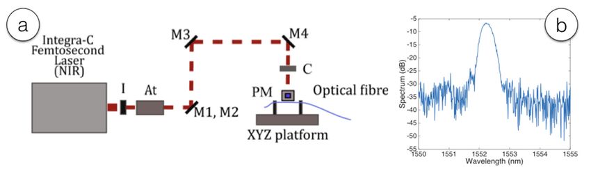
Appl. Sci. 2019, 9, 3107                                                                               2 of 10

FBGs find many applications in telecommunications [1], in signal equalization [3], and as reflectors for
laser cavity in fiber lasers [4]. FBGs are also popular for sensing, as the Bragg wavelength shifts when
temperature or strain variations are applied to the grating [5], making it a compact sensing device that
finds numerous fields of application.
      The first generation of FBGs have been fabricated using photosensitive fibers [1], having a
significant Ge-doping that facilitates the process of FBG inscription, and on standard single-mode
fibers (SMFs) by means of H2 loading [6]. More recently, the possibility to use a femtosecond (fs) laser
focused on the fiber core has opened the possibility of inscribing an FBG on several types of fibers [7,8].
SMF fibers have low attenuation and adhere to telecommunication standards (such as ITU-T G.657.A1
and G.652.D), and the possibility of inscribing FBGs into such fibers gives rise to wavelength filters
and sensors at a relatively low cost, and easy to be interconnected.
      With the emergence of research on specialty fibers, engineered in order to achieve specific functions
that SMFs cannot achieve, new sensing functions can be enabled. In this sense, the possibility of
inscribing FBGs in specialty fibers has provided the backbone for advanced applications in sensing and
fiber lasers, particularly thanks to direct inscription. Among others, Iadicicco et al. [9] reported FBGs
in microstructured fibers which add refractive index sensitivity to the inherent temperature/strain
sensitivity; Jovanovic et al. [10] reported FBGs directly inscribed with a point-by-point technique
in the inner core of a dual-core fiber, which represents the end reflectors of a fiber laser cavity;
Leal-Junior et al. [11] reported FBGs inscribed in a polymer fiber in the infrared, which achieves a much
larger sensitivity to temperature effects, and reports also a humidity sensitivity; Pugliese et al. [12]
reported FBGs inscribed in a bioresorbable fiber, which has the property of being potentially absorbed
by the human body after use.
      Among the specialty fibers used in sensing applications, several efforts have been recently devoted
to altering the Rayleigh scattering properties of fibers. In this scenario, three main approaches have
given similar results. Yan et al. [13] reported a method based on rapid pulses with a fs laser (300 nJ
at 250 kHz repetition rate), increasing the scattering level of a SMF by up to 45 dB. Parent et al. [14]
have obtained similar results, with a scattering increment of 37 dB, by means of exposure to intense
ultraviolet light; this method has also been used to generate random gratings [15]. More recently,
Beisenova et al. [16] have obtained a 36.5 dB scattering increment by using a MgO-nanoparticle-doped
(MgO-NP) fiber as sensing medium. This setup has also been used to design a scattering-level
multiplexing [16,17], a new domain of multiplexing where the diversity is given by the scattering
level at each sensing point. While the first two methods are characterized by a specific fabrication at
one specific sensing point, the third method provides an optical fiber that can be spooled and spliced
directly to a SMF, making the operation of building a multi-fiber sensing network much simpler.
      The possibility to increase the scattering of a fiber is intriguing in distributed sensing, particularly
using optical backscatter reflectometry (OBR) [18], whereas the analyzer detects the distributed
Rayleigh scattering backreflection occurring in each region of the fiber. In such system, by increasing
the Rayleigh scattering a larger signal at the analyzer can be obtained [13–17], over 3–4 orders of
magnitude larger when properly tuning scattering properties.
      In this work, the characterization of FBGs on a high-scattering MgO-NP fiber is presented.
The possibility to have an FBG on such fiber opens important applications for sensing, as it allows
tagging a specific sensing point as reference and measuring a sensing region relatively to the FBG.
Also, due the polarization-sensitive behavior of the fiber, a different sensitivity for each polarization
state can be observed. In the following, the experimental results of FBG inscription into a MgO-NP
and the characterization of the grating for thermal effects, including a polarization-sensitive analysis,
will be reported.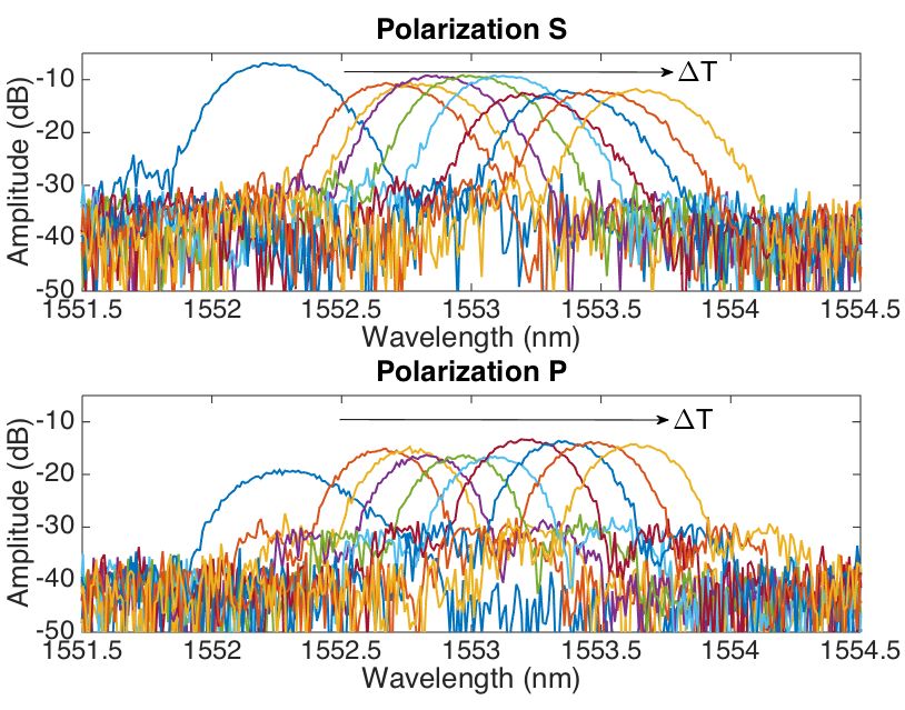
Appl. Sci. 2019, 9, 3107 3 of 10
2.Appl.
Fabrication
Sci. 2019, 9, and
x FORSetup
PEER REVIEW 3 of 10
2.1. MgO
The Nanoparticle-Doped
fiber used in this work Fiberpresents a core doped with a random pattern of nanoparticles whose
composition
The fiberisused
based on MgO
in this work[17,19].
presentsThe fiber,doped
a core designed
withtoa improve the efficiency
random pattern of C-band whose
of nanoparticles optical
amplifier (wavelengths from 1530 to 1565 nm), presents an additional doping
composition is based on MgO [17,19]. The fiber, designed to improve the efficiency of C-band optical of erbium in the core.
The fiber (wavelengths
amplifier possesses the typical telecom
from 1530 size,
to 1565 i.e.,presents
nm), core diameter of 10 μmdoping
an additional and cladding
of erbiumdiameter
in theof 125
core.
μm, and a protective jacket with 250 μm diameter. This fact permits simple splicing
The fiber possesses the typical telecom size, i.e., core diameter of 10 µm and cladding diameter of 125 µm, operation with
standard
and SMF-28
a protective pigtails.
jacket Theµm
with 250 preform of the
diameter. Thisfiber
facthas beensimple
permits fabricated by aoperation
splicing conventional Modified
with standard
Chemical
SMF-28 VaporThe
pigtails. Deposition
preform of (MCVD)
the fiberprocess,
has beena fabricated
common by technique
a conventionalfor specialty
Modified optical fibers
Chemical
fabrication.
Vapor Deposition (MCVD) process, a common technique for specialty optical fibers fabrication.
Theproposed
The proposed technology
technology allowsallows
one toone
growtoin-situ
growoxidein-situ oxide nanoparticles
nanoparticles due to high
due to high temperatures
temperatures
reached duringreached
the MCVD during the [19]
process MCVD process [19] The
The implemented implemented
principle is based on principle is based on
the spontaneous the
phase
spontaneous phase separation process. This process involves the immiscibility
separation process. This process involves the immiscibility of silicate compound that contain alkaline of silicate compound
that contain
earth ions (MO,alkaline
whereearth
M = ions
Mg, (MO,
Ca or where
Sr). TheMresult
= Mg,isCa or the
that Sr). compound
The result is that
will the compound
decompose will
into two
decompose into two phases: one silica-rich and one MgO-rich in shape of spherical
phases: one silica-rich and one MgO-rich in shape of spherical particles. The characteristics of the particles. The
characteristics of the nanoparticles (size, size distribution) depends on the concentration
nanoparticles (size, size distribution) depends on the concentration of Mg, but typically the process of Mg, but
typically nanoparticle
generates the process generates
whose size,nanoparticle
location and whose size, location
refractive index areand refractive
random. The index
size isare random.
in between
The size is in between 20 nm and 100 nm, while the refractive index is in between
20 nm and 100 nm, while the refractive index is in between 1.53 to 1.65. The presence of nanoparticle 1.53 to 1.65. The
presence of nanoparticle strongly enhances the
strongly enhances the scattering and the losses [17,18]. scattering and the losses [17,18].
2.2.Fiber
2.2. FiberBragg
BraggGrating
GratingInscription
Inscription
Theinscription
The inscription ofofFBGs
FBGsononthetheMgO-NP
MgO-NP fiberfiberhas
hasbeen
beencarried
carriedout
outbybymeans
meansofofaafsfslaser
laserand
and
phasemask
phase maskmethod
method[10,11]
[10,11][20],
[20],using
usingthe
thesetup
setupsketched
sketchedininFigure
Figure1a.1a. The
The optical
optical fiber
fiberhashasbeen
been
placedbetween
placed betweentwotwofiber
fiberholders,
holders,leaving
leavingthethestripped
strippedMgO-NP
MgO-NPfiber fibersection
sectionexposed
exposedto tothe
thephase
phase
maskarea.
mask area.With
Withthis
thissetup,
setup,two
twoFBGs
FBGshave
havebeen
beeninscribed,
inscribed,at
at33cm
cmdistance
distancefrom
fromeach
eachother.
other.The
Thefirst
first
FBGhas
FBG has22mmmmlength,
length,and
andBragg
Braggwavelength
wavelengthof of1538.5
1538.5nm
nm(phase
(phasemask
maskwith
withaapitch
pitchofof1061
1061nm)nm)at at
roomtemperature;
room temperature;the thesecond
secondFBG
FBGhashas44mmmmlength,
length,and
andBragg
Braggwavelength
wavelengtharound
around1552.2
1552.2nm nm(phase
(phase
maskwith
mask withaapitch
pitchofof1072
1072nm)
nm)atatroom
room temperature.
temperature. The
The spectrum
spectrum of of
thethe second
second FBG,
FBG, thetheoneone used
used in
in the spectral and polarization analysis, is reported in
the spectral and polarization analysis, is reported in Figure 1b.Figure 1b.
Figure1.1.(a)
Figure (a)Schematic
Schematicdiagram
diagramofof the
the laser
laser inscription
inscription setup
setup usedused to inscribe
to inscribe refractive
refractive gratings;
gratings; I—
I—iris,
iris, At—power
At—power attenuator,
attenuator, M—mirror,
M—mirror, C—Convex
C—Convex cylindrical
cylindrical lens, PM—Phase
lens, PM—Phase mask.
mask. (b) (b) Spectrum
Spectrum of the
of the
FBG FBG inscribed
inscribed on the MgO-NP
on the MgO-NP having having Bragg wavelength
Bragg wavelength aroundaround 1552.2 nm.
1552.2 nm.
2.3. Experimental Characterization Setup
2.3. Experimental Characterization Setup
The analysis of FBG spectra, as well as of the MgO-NP fiber, has been performed using a commercial
The analysis of FBG spectra, as well as of the MgO-NP fiber, has been performed using a
OBR analyzer (Luna OBR4600, Luna Inc., Roanoke, VA, USA). The setup used in measurements is
commercial OBR analyzer (Luna OBR4600, Luna Inc., Roanoke, VA, USA). The setup used in
shown in Figure 2, including both a schematic diagram and the photograph of the whole system.
measurements is shown in Figure 2, including both a schematic diagram and the photograph of the
The MgO-NP fiber has been spliced to a lead-in SMF span by means of a standard splicer (SMF-SMF
whole system. The MgO-NP fiber has been spliced to a lead-in SMF span by means of a standard
splicing recipe, cladding alignment, Fujikura 12-S, Tokyo, Japan). The OBR has been used with the
splicer (SMF-SMF splicing recipe, cladding alignment, Fujikura 12-S, Tokyo, Japan). The OBR has
following parameters: wavelength range 1525.0–1610.5 nm, resolution bandwidth 1.29 GHz (10.3 pm),
been used with the following parameters: wavelength range 1525.0–1610.5 nm, resolution bandwidth
1.29 GHz (10.3 pm), 8192 wavelength points, no gain for each detector; the OBR spatial resolution is
9.8 μm. The OBR detects both polarizations, here labelled S (perpendicular) and P (parallel), where
the orientation is referred to the swept laser of the OBR source [21].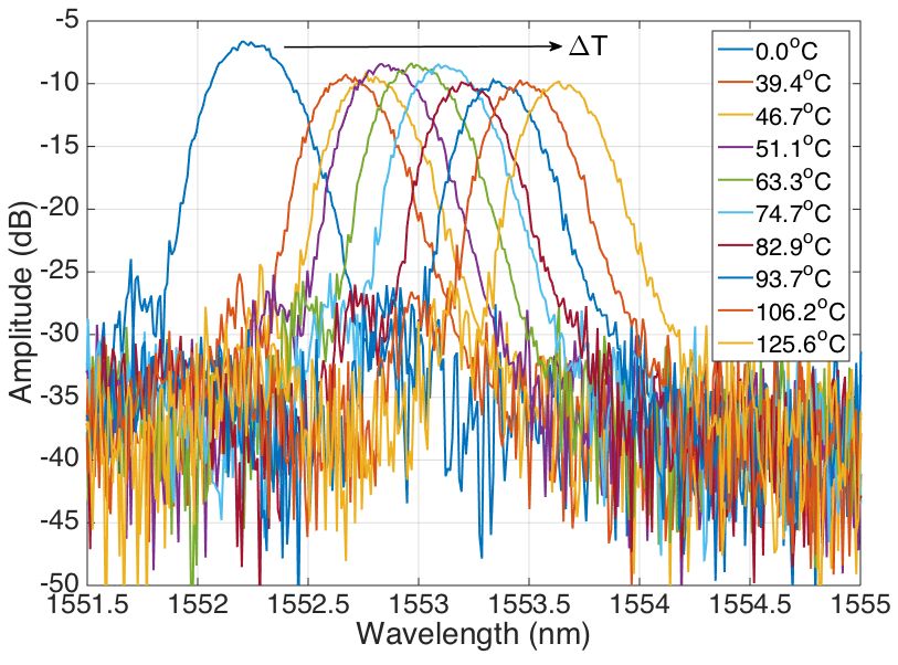
Appl. Sci. 2019, 9, 3107 4 of 10
8192 wavelength points, no gain for each detector; the OBR spatial resolution is 9.8 µm. The OBR
detects both polarizations, here labelled S (perpendicular) and P (parallel), where the orientation is
referred to 2019,
Appl. Sci. the swept
9, x FORlaser of the OBR source [21].
PEER REVIEW 4 of 10
Figure
Figure 2. Setup
2. Setup of of
thethe FBGinterrogation
FBG interrogationsystem.
system. (a)
(a) Schematic
Schematicdiagram
diagramofof
the setup;
the (b)(b)
setup; photograph.
photograph.
Thermal
Thermal variationshave
variations havebeen
been obtained
obtainedby byplacing thethe
placing fiber in contact
fiber with with
in contact a heating plate (C-
a heating plate
MAG HS4, IKA, Staufen, Germany). The reference temperature has been measured
(C-MAG HS4, IKA, Staufen, Germany). The reference temperature has been measured by anotherby another FBGFBG
(ormoceramic
(ormoceramic draw-towergrating
draw-tower gratingDTG-1550
DTG-1550 nm,nm,FBGS
FBGSInternational,
International,Geel, Belgium)
Geel, connected
Belgium) to a to
connected
commercial FBG interrogator (si255, 1 kHz, Micron Optics, Atlanta, GA, USA) and detecting the peak
a commercial FBG interrogator (si255, 1 kHz, Micron Optics, Atlanta, GA, USA) and detecting the
wavelength with ~0.1 pm accuracy; the thermal sensitivity of the reference FBG is 10.4 pm/°C. The
peak wavelength with ~0.1 pm accuracy; the thermal sensitivity of the reference FBG is 10.4 pm/◦ C.
hot plate temperature has been varied from 60°C to 145°C, approximately 40–125°C over the room
The hot plate temperature has been varied from 60◦ C to 145◦ C, approximately 40–125◦ C over the room
temperature of ◦20°C. In order to maintain a heat uniformity, we the hot plate has been covered with
temperature
a beaker. of 20 C. In order to maintain a heat uniformity, we the hot plate has been covered with
a beaker.
3. Experimental Results
3. Experimental Results
3.1. Characterization of Fiber Bragg Grating
3.1. Characterization of Fiber Bragg Grating
The result of FBGs inscription on the MgO-NP fiber is shown in Figure 3, which displays the
The result
power of FBGsatinscription
backreflected each section onofthe
theMgO-NP fiberpolarizations.
fiber for both is shown in Figure 3, which
The lead-in fiber displays
is a SMF, the
power
which has a scattering level around −91 dB and terminates at 4.58 m length (measured from SMF,
backreflected at each section of the fiber for both polarizations. The lead-in fiber is a the OBRwhich
has lead-out
a scattering
connector). In the −91
level around MgO-NPdB and terminates
section, at 4.58a m
we observe length (measured
scattering gain, whichfromis thethe OBR lead-out
increment of
connector).
scatteringInwith
the respect
MgO-NP section,
to the SMF, we observe
of 37.2 a scattering
dB, similar to [17].gain,
Due to which is the
the high increment
scattering, theof scattering
fiber has
witha high two-way
respect to theloss
SMF,estimated
of 37.2 as dB,22.1 dB/m,to
similar i.e., cumulating
[17]. Due to the bothhigh
the forward and the
scattering, backward
fiber haswave.a high
Two FBGs have been inscribed at the lengths of 4.60 m and 4.63
two-way loss estimated as 22.1 dB/m, i.e., cumulating both the forward and backward wave. m. The first FBG exhibits a signal
increment
Two FBGs ofhave
~10 dB
beenover the scattering
inscribed at the level andofcorresponds
lengths 4.60 m andto a relatively
4.63 weak
m. The first FBGFBG; the second
exhibits a signal
FBG is stronger (28 dB over the scattering trace) and represents a strong FBG.
increment of ~10 dB over the scattering level and corresponds to a relatively weak FBG; the second We also observe that
the polarization appears to fluctuate along the MgO-NP fiber, as previously observed
FBG is stronger (28 dB over the scattering trace) and represents a strong FBG. We also observe that the in [22].
We report in Figure 4 the reflection spectrum of the stronger of the two MgO-NP FBGs, i.e., the
polarization appears to fluctuate along the MgO-NP fiber, as previously observed in [22].
grating inscribed at the length of 4.63 m as the temperature increases; the results are similar to the
We report in Figure 4 the reflection spectrum of the stronger of the two MgO-NP FBGs, i.e., the
FBG inscribed at 4.60 m. The reflection spectrum of the FBG appears as ~28 dB over the noise floor,
grating inscribed at the length of 4.63 m as the temperature increases; the results are similar to the
in compliance with Figure 3. As for a standard FBG, the spectrum appears to shift towards longer
FBGwavelengths
inscribed atas4.60
the m. The reflection
temperature spectrum
variation of the FBG
ΔT increases fromappears as ~28
the reference dB over
value, the noisethe
maintaining floor,
in compliance
spectral shape.with
AtFigure 3. As
the initial for a standard
temperature (ΔT = FBG,
0 °C, the spectrum appears
corresponding to the roomto shift towards longer
temperature) the
Bragg wavelength is 1552.2 nm, and rises to 1553.6 nm for ΔT = 125.6 °C, at the maximum
temperature.Appl. Sci. 2019, 9, 3107 5 of 10
wavelengths as the temperature variation ∆T increases from the reference value, maintaining the
spectral shape. At the initial temperature (∆T = 0 ◦ C, corresponding to the room temperature) the
Bragg wavelength is 1552.2 nm, and rises to 1553.6 nm for ∆T = 125.6 ◦ C, at the maximum temperature.
Appl. Sci.
Appl. Sci. 2019,
2019, 9,
9, xx FOR
FOR PEER
PEER REVIEW
REVIEW 55 of
of 10
10
Figure 3.
Figure
Figure 3. Backreflected
3. Backreflected signal
signal for
for from
from the
the MgO-NP
MgO-NP fiber
fiber with
with 22 FBGs
FBGs inscribed
inscribed at
at 4.60
4.60 m
m and
and 4.63
4.63 m.
m.
Figure 4. Reflection
Figure 4. Reflection spectra
Reflectionspectra ofofthe
spectraof the MgO-NP
theMgO-NP
MgO-NP FBG, forfor
FBG,
FBG, for different values
different
different of temperature
values
values of temperature variation
of temperature ΔT; ∆T;
variation
variation ΔT; the
the
the reference
reference
reference temperature ΔT ==∆T
temperature
temperature ΔT = 0corresponds
00 °C
°C ◦ C corresponds
corresponds to room
to room
to room temperature.
temperature.
temperature.
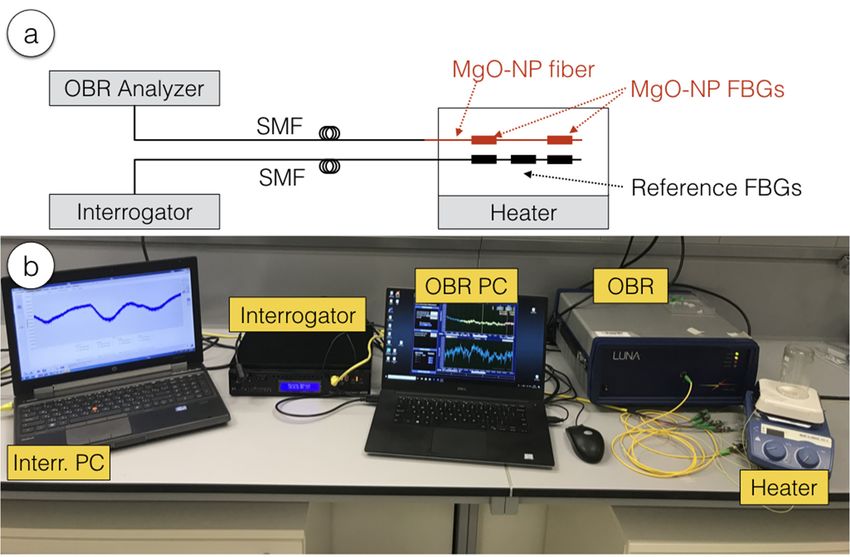
Figure
Figure 555 reports
Figure reports the
reports theBragg
the Braggwavelength
Bragg wavelengthof
wavelength ofofthe
thetheFBG
FBG
FBG asas
as a function
aa function
function of the
of the
of the temperature
temperature
temperature variation.
variation.
variation. As
As
As in [1,5], the FBG shows a linear wavelength shift, with sensitivity equal to 11.45 pm/◦ C and reference
in [1,5], the FBG shows a linear wavelength shift, with sensitivity equal to 11.45 pm/°C
in [1,5], the FBG shows a linear wavelength shift, with sensitivity equal to 11.45 pm/°C and reference and reference
R22 =
wavelength 2
wavelength of
wavelength of 1552.262
of 1552.262 nm;
1552.262 nm; the
nm; the fit
the fit has
fit has coefficient
has coefficient of
coefficient of determination
of determination R
determination R 0.997, which
== 0.997,
0.997, which shows
which shows aaa very
shows very
very
accurate fit for over 125 ◦ C of temperature range.
accurate fit for over 125°C of temperature
accurate fit for over 125°C of temperature range. range.Appl. Sci. 2019, 9, 3107 6 of 10
Appl. Sci. 2019, 9, x FOR PEER REVIEW 6 of 10
Figure 5.
Figure 5. Bragg
Bragg wavelength
wavelength of
of the
the MgO-NP
MgO-NP FBG FBG as
as aa function
function of
of the
the temperature variation. The
temperature variation. The chart
chart
shows the measured data and the linear fit (11.45 pm/°C,
◦ R22 = 0.997).
shows the measured data and the linear fit (11.45 pm/ C, R = 0.997).
3.2. Polarization Analysis
As previously outlined in [22], the MgO-NP fiber induces a beat length of polarization that has
a higher frequency than aa standard
standard SMF,
SMF, with
with polarization
polarization switching
switching every
every few
few centimeters.
centimeters. This
effect is common with the other methods proposed for enhancing the Rayleigh backscattering of the
fiber [13–15]. Thus, in this section we investigate the polarization-sensitive behaviorbehavior of the FBG, by
separating the S/P polarizations into the analysis.
polarizations into the analysis.
The polarization effects are shown in Figure 6, which reports the FBG spectra for S and P
polarizations. At At first,
first, we
we observe
observe aa different
different amplitude
amplitude between
between the the two
two spectra, with the S
polarization having a higher value, but also fluctuating as the temperature increases.increases. The spectra for
the polarization P appear narrower in bandwidth, and as temperature increases we observe that the
spectra at the P polarization take a different
different wavelength
wavelength shift
shift than
than the
the spectra
spectrafor
forthe
thepolarization
polarizationS.
S.
We can analyse independently the two polarizations, and determine the sensitivity to temperature
at each wavelength; this analysis is shown in Figure 7. We observe a linear pattern for both polarizations,
with thermal sensitivity of 11.53 pm/◦ C for the polarization S (R2 = 0.997) and 11.08 pm/◦ C for the
polarization P (R2 = 0.995). The analysis shows a significant deviation between the two polarizations,
as the sensitivity for the S polarization (the dominant one, given its higher amplitude) is 4.0% higher
than for the P polarization; this is a reliable measurement given the fidelity of the linear fit, as the R2
term is higher than 0.99 for both estimates. At room temperature, the Bragg wavelength is higher
for the polarization P and lower for the S; as temperature increases however we see a progressive
divergence between the Bragg wavelengths for both polarization states.
A polarization analysis is carried out in Figure 8, reporting the FBG bandwidth (estimated as
the full-width half-maximum, FWHM) and the maximum spectral amplitude for each polarization.
At first, we observe an interesting pattern for the FWHM, which at room temperature is wider for the
P polarization (as shown in Figure 6) where the minimum amplitude is recorded; as the temperature
increases, the FWHM assumes different values for the 2 polarization, and is equal to 0.33–0.35 nm for
the S polarization and to 0.27–0.28 nm for the P polarization, showing a significant deviation which is
also clear as the spectra are plotted in Figure 6.separating the S/P polarizations into the analysis.
The polarization effects are shown in Figure 6, which reports the FBG spectra for S and P
polarizations. At first, we observe a different amplitude between the two spectra, with the S
polarization having a higher value, but also fluctuating as the temperature increases. The spectra for
the polarization P appear narrower in bandwidth, and as temperature increases we observe that the
Appl. Sci. 2019, 9, 3107 7 of 10
spectra at the P polarization take a different wavelength shift than the spectra for the polarization S.
Appl. Sci. 2019, 9, x FOR PEER REVIEW 7 of 10
Figure 6. Reflection spectra of the FBG on MgO-NP fiber, evaluated for S (upper) and P (lower)
polarizations.
We can analyse independently the two polarizations, and determine the sensitivity to
temperature at each wavelength; this analysis is shown in Figure 7. We observe a linear pattern for
both polarizations, with thermal sensitivity of 11.53 pm/°C for the polarization S (R2 = 0.997) and 11.08
pm/°C for the polarization P (R2 = 0.995). The analysis shows a significant deviation between the two
polarizations, as the sensitivity for the S polarization (the dominant one, given its higher amplitude)
is 4.0% higher than for the P polarization; this is a reliable measurement given the fidelity of the linear
fit, as the R2 term is higher than 0.99 for both estimates. At room temperature, the Bragg wavelength
is higher for the polarization P and lower for the S; as temperature increases however we see a
progressive divergence between the Bragg wavelengths for both polarization states.
A polarization analysis is carried out in Figure 8, reporting the FBG bandwidth (estimated as the
full-width half-maximum, FWHM) and the maximum spectral amplitude for each polarization. At
first, we observe an interesting pattern for the FWHM, which at room temperature is wider for the P
polarization (as shown in Figure 6) where the minimum amplitude is recorded; as the temperature
increases, the FWHM assumes different values for the 2 polarization, and is equal to 0.33–0.35 nm for
the SFigure
polarization and to 0.27–0.28
6. Reflection spectra ofnm
thefor the on
FBG P polarization,
MgO-NP fiber,showing a significant
evaluated deviation
for S (upper) and Pwhich
is also clear polarizations.
(lower) as the spectra are plotted in Figure 6.
Figure 7. Bragg wavelength for each polarization as a function of the temperature variation.
Figure 7. Bragg wavelength for each polarization as a function of the temperature variation.
The amplitude
The amplitude ofof the
the spectral
spectral response
response also
also shows
shows aa temperature-dependent
temperature-dependent pattern,
pattern, as
as the
the light
light
appears to transfer from the S to P polarization as the temperature increases. At room temperature,
appears to transfer from the S to P polarization as the temperature increases. At room temperature,
the polarization
the polarizationdifference
differenceisisover
over1212 dB,
dB, butbut reaches
reaches a minimum
a minimum of dB
of 0.6 0.6 at
dB∆Tat=ΔT
75=◦ C,
75 where
°C, where the
the two
two polarizations
polarizations have similar
have similar amplitude;amplitude;
at higherattemperature,
higher temperature,
the processthe process
reverses andreverses and S
S polarization
polarization appears to have
appears to have higher amplitude.higher amplitude.Appl. Sci. 2019, 9, 3107 8 of 10
Appl. Sci. 2019, 9, x FOR PEER REVIEW 8 of 10
Figure 8. Polarization analysis of the FBG parameters: the chart reports the FWHM (left) and the
Figure 8. Polarization analysis of the FBG parameters: the chart reports the FWHM (left) and the
maximum amplitude (right) of the FBG spectra at different temperature values, for the whole FBG
maximum amplitude (right) of the FBG spectra at different temperature values, for the whole FBG and
and for each polarization independently.
for each polarization independently.
4. Discussion
4. Discussion
TheThe characterization
characterization ofof FBGson
FBGs onaahigh-scattering
high-scattering MgO-NP
MgO-NPfiber, fiber,with
withenhanced
enhanced backscattering
backscattering
properties, has implications, particularly in terms of sensing and polarization effects, as it can provide
properties, has implications, particularly in terms of sensing and polarization effects, as it can provide
an additional layer of complexity in sensing.
an additional layer of complexity in sensing.
The main difference between the MgO-NP fiber and the other methods for enhancing the
The main difference between the MgO-NP fiber and the other methods for enhancing the
backscattering is that the first one can be used, effectively, as a fiber, and thus the FBG is part of the
backscattering is that
optical circuitry usedthetofirst one canfiltering
implement be used, andeffectively, as a[4,10],
cavity effects fiber,as
andwellthus the
as to FBGdistributed
create is part of the
optical circuitry
reflectors used toby
supported implement
the random filtering
effect and cavity
of the effectsnanoparticles
scattering [4,10], as well as to
[23]. In create
sensing, distributed
this is
reflectors supported by the random effect of the scattering nanoparticles
important as the FBG allows “tagging” a specific sensing point where the FBG is located, and [23]. In sensing, this is
important
referencing the remainder of the fiber to the valued measured in this location, enabling solutions thatand
as the FBG allows “tagging” a specific sensing point where the FBG is located,
referencing
mix opticalthe frequency
remainderdomainof the fiber to the valued
reflectometry of fibermeasured
scatteringin and
this FBG
location, enabling[24,25].
interrogation solutions Thethat
mix main application
optical frequency fordomain
the MgO-NP fiber is inofscattering-level
reflectometry fiber scatteringmultiplexing, which requires
and FBG interrogation a fiber
[24,25]. Thewith
main
high Rayleigh scattering in order to simultaneously detect multiple channels
application for the MgO-NP fiber is in scattering-level multiplexing, which requires a fiber with high on the OBR device
[16,17].scattering
Rayleigh The addition of FBGs
in order to to this sensing system
simultaneously detect canmultiple
be used to extend the
channels on sensing
the OBR length
device of each
[16,17].
The addition of FBGs to this sensing system can be used to extend the sensing length of each level,
channel, by using the additional reflectivity of the FBG in addition to the scattering channel,
compensating
by using for thereflectivity
the additional relative inline highFBG
of the losses of the fiber.
in addition to the scattering level, compensating for the
In addition, the different sensitivity exhibited by the polarizations to thermal effects is a
relative inline high losses of the fiber.
significant effect, as the difference is estimated as 4% with a good degree of confidence (R2 > 0.99). In
In addition, the different sensitivity exhibited by the polarizations to thermal effects is a significant
comparison, this difference is 0.5% for a fiber doped with MgO nanoparticles but having no scattering
effect, as the difference is estimated as 4% with a good degree of confidence (R2 > 0.99). In comparison,
enhancement, and isAppl. Sci. 2019, 9, 3107 9 of 10
between the two Bragg wavelengths, which is ~0.5 nm in [28]. It is noteworthy that the polarization
effect is not obtained by asymmetrical design of the fiber [29], but is routed in the scattering content of
the MgO nanoparticles. Overall, the results presented in this work open the possibility to thermally
tune the wavelength and polarization of the FBGs inscribed on this fiber, considering also the different
bandwidth exhibited by the two polarization states.
5. Conclusions
The characterization of FBGs onto a specialty fiber doped with MgO nanoparticles having enhanced
Rayleigh scattering is reported in this work. The MgO-NP fiber has 37.2 dB scattering increment over
a SMF, and 22.1 dB/m two-way loss. The FBGs achieved up to 28 dB amplitude over the scattering
level. A thermal characterization shows the sensitivity to be 11.45 pm/◦ C, similar to standard glass
fibers; the thermal sensitivity exhibits a 4% difference between the two S/P polarizations (respectively,
11.53 pm/◦ C and 11.08 pm/◦ C). Future work will consist on exploiting the polarization properties for
sensing applications, and on the analysis of the high-scattering impact in FBG sensing networks.
Author Contributions: C.M., C.M., W.B., and D.T. conceptualized the work; W.B. fabricated the optical fiber
used in experiments; T.P., P.A., R.M., and C.M. inscribed Bragg gratings into the fiber; C.M., A.B. prepared
the characterization setup; C.M., A.B., D.T. performed the characterization of the Bragg gratings; C.M., C.M.,
W.B., D.T. analyzed and prepared the data; D.T., C.M., W.B., C.M., wrote the article; all authors reviewed data
and manuscript.
Funding: This work has been funded by: ORAU program at Nazarbayev University through grants LIFESTART
(PI: Daniele Tosi) and FOSTHER (PI: Carlo Molardi); ANR project NanoSlim (ANR-17-17-CE08-0002); FCT –
Fundação para a Ciência e a Tecnologia, I.P., in the scope of the framework contract foreseen in the numbers
4, 5 and 6 of the article 23, of the Decree-Law 57/2016, of August 29, changed by Law 57/2017, of July 19, and
when applicable co-funded by FEDER—PT2020 partnership agreement under the project UID/CTM/50025/2019.
Tiago Paixão was funded by Fundação para a Ciência e Tecnologia (FCT) for the grant with the references
PD/BD/128265/2016.
Conflicts of Interest: The authors declare no conflict of interest.
References
1. Othonos, A.; Kalli, K. Fiber Bragg Gratings: Fundamentals and Applications in Telecommunications and Sensing;
Artech House: Boston, MA, USA, 1999.
2. Erdogan, T. Fiber grating spectra. J. Light. Technol. 1997, 15, 1277–1294. [CrossRef]
3. Liaw, S.K.; Ho, K.P.; Chi, S. Dynamic power-equalized EDFA module based on strain tunable fiber Bragg
gratings. IEEE Photonics Technol. Lett. 1999, 11, 797–799. [CrossRef]
4. Chow, J.; Town, G.; Eggleton, B.; Ibsen, M.; Sugden, K.; Bennion, I. Multiwavelength generation in an
erbium-doped fiber laser using in-fiber comb filters. IEEE Photonics Technol. Lett. 1996, 8, 60–62. [CrossRef]
5. Kersey, A.D.; Davis, M.A.; Patrick, H.J.; LeBlanc, M.; Koo, K.P.; Askins, C.G.; Putnam, M.A.; Friebele, E.J.
Fiber grating sensors. J. Light. Technol. 1997, 15, 1442–1463. [CrossRef]
6. Liou, C.L.; Wang, L.A.; Shih, M.C. Characteristics of hydrogenated fiber Bragg gratings. Appl. Phys. A 1997,
64, 191–197. [CrossRef]
7. Liao, C.R.; Wang, D.N. Review of femtosecond laser fabricated fiber Bragg gratings for high temperature
sensing. Photonic Sens. 2013, 3, 97–101. [CrossRef]
8. Mihailov, S.J.; Grobnic, D.; Smelser, C.W.; Lu, P.; Walker, R.B.; Ding, H. Bragg grating inscription in various
optical fibers with femtosecond infrared lasers and a phase mask. Opt. Mater. Express 2011, 1, 754–765. [CrossRef]
9. Iadicicco, A.; Campopiano, S.; Cutolo, A.; Giordano, M.; Cusano, A. Refractive index sensor based on
microstructured fiber Bragg grating. IEEE Photonics Technol. Lett. 2005, 17, 1250–1252. [CrossRef]
10. Jovanovic, N.; Åslund, M.; Fuerbach, A.; Jackson, S.D.; Marshall, G.D.; Withford, M.J. Narrow linewidth,
100 W cw Yb 3+-doped silica fiber laser with a point-by-point Bragg grating inscribed directly into the active
core. Opt. Lett. 2007, 32, 2804–2806. [CrossRef]
11. Leal-Junior, A.; Frizera, A.; Marques, C.; Pontes, M.J. Mechanical properties characterization of polymethyl
methacrylate polymer optical fibers after thermal and chemical treatments. Opt. Fiber Technol. 2018, 43,
106–111. [CrossRef]Appl. Sci. 2019, 9, 3107 10 of 10
12. Pugliese, D.; Konstantaki, M.; Konidakis, I.; Ceci-Ginistrelli, E.; Boetti, N.G.; Milanese, D.; Pissadakis, S.
Bioresorbable optical fiber Bragg gratings. Opt. Lett. 2018, 43, 671–674. [CrossRef] [PubMed]
13. Yan, A.; Huang, S.; Li, S.; Chen, R.; Ohodnicki, P.; Buric, M.; Lee, S.; Li, M.J.; Chen, K.P. Distributed optical
fiber sensors with ultrafast laser enhanced Rayleigh backscattering profiles for real-time monitoring of solid
oxide fuel cell operations. Sci. Rep. 2017, 7, 9360. [CrossRef] [PubMed]
14. Parent, F.; Loranger, S.; Mandal, K.K.; Iezzi, V.L.; Lapointe, J.; Boisvert, J.S.; Baiad, M.D.; Kadoury, S.;
Kashyap, R. Enhancement of accuracy in shape sensing of surgical needles using optical frequency domain
reflectometry in optical fibers. Biomed. Opt. Express 2017, 8, 2210–2221. [CrossRef] [PubMed]
15. Monet, F.; Loranger, S.; Lambin-Iezzi, V.; Drouin, A.; Kadoury, S.; Kashyap, R. The ROGUE: A novel,
noise-generated random grating. Opt. Express 2019, 27, 13895–13909. [CrossRef] [PubMed]
16. Beisenova, A.; Issatayeva, A.; Sovetov, S.; Korganbayev, S.; Jelbuldina, M.; Ashikbayeva, Z.; Blanc, W.;
Schena, E.; Sales, S.; Molardi, C.; et al. Multi-fiber distributed thermal profiling of minimally invasive thermal
ablation with scattering-level multiplexing in MgO-doped fibers. Biomed. Opt. Express 2019, 10, 1282–1296.
[CrossRef] [PubMed]
17. Beisenova, A.; Issatayeva, A.; Korganbayev, S.; Molardi, C.; Blanc, W.; Tosi, D. Simultaneous distributed
sensing on multiple MgO-doped high scattering fibers by means of scattering-level multiplexing.
J. Light. Technol. 2019, 37, 3413–3421. [CrossRef]
18. Froggatt, M.; Moore, J. High-spatial-resolution distributed strain measurement in optical fiber with Rayleigh
scatter. Appl. Opt. 1998, 37, 1735–1740. [CrossRef]
19. Blanc, W.; Mauroy, V.; Nguyen, L.; Shivakiran Bhaktha, B.N.; Sebbah, P.; Pal, B.P.; Dussardier, B. Fabrication
of rare earth-doped transparent glass ceramic optical fibers by modified chemical vapor deposition. J. Am.
Ceram. Soc. 2011, 94, 2315–2318. [CrossRef]
20. Marques, C.; Leal-Junior, A.; Min, R.; Domingues, M.; Leitão, C.; Antunes, P.; Ortega, B.; André, P. Advances
on polymer optical fiber gratings using a KrF pulsed laser system operating at 248 nm. Fibers 2018, 6, 13.
[CrossRef]
21. Soller, B.J.; Wolfe, M.; Froggatt, M.E. Polarization resolved measurement of Rayleigh backscatter in fiber-optic
components. In Proceedings of the National Fiber Optic Engineers Conference, Anaheim, CA, USA,
6 March 2005; p. NWD3.
22. Molardi, C.; Korganbayev, S.; Blanc, W.; Tosi, D. Characterization of a nanoparticles-doped optical fiber by
the use of optical backscatter reflectometry. In Proceedings of the SPIE Photonics Asia, Advanced Sensor
Systems and Applications VIII, Beijing, China, 11–13 October 2018; Volume 10821, p. 1082121.
23. Lizárraga, N.; Puente, N.P.; Chaikina, E.I.; Leskova, T.A.; Méndez, E.R. Single-mode Er-doped fiber random
laser with distributed Bragg grating feedback. Opt. Express 2009, 17, 395–404. [CrossRef] [PubMed]
24. Koeppel, M.; Werzinger, S.; Ringel, T.; Bechtold, P.; Thiel, T.; Engelbrecht, R.; Bosselmann, T.; Schmauss, B.
Combined distributed Raman and Bragg fiber temperature sensing using incoherent optical frequency
domain reflectometry. J. Sens. Sens. Syst. 2018, 7, 91–100. [CrossRef]
25. Xu, J.; Dziong, Z.; Cabani, A. Simultaneous temperature sensing using distributed cascading fiber Bragg
grating-based single-ended Brillouin optical time-domain analyzer. Laser Phys. 2018, 28, 125101. [CrossRef]
26. Lu, P.; Grobnic, D.; Mihailov, S.J. Characterization of the birefringence in fiber Bragg gratings fabricated with
an ultrafast-infrared laser. J. Light. Technol. 2007, 25, 779–786. [CrossRef]
27. Oh, S.T.; Han, W.T.; Paek, U.C.; Chung, Y. Discrimination of temperature and strain with a single FBG based
on the birefringence effect. Opt. Express 2004, 12, 724–729. [CrossRef] [PubMed]
28. Van Roosbroeck, J.; Ibrahim, S.K.; Lindner, E.; Schuster, K.; Vlekken, J. Stretching the limits for the decoupling
of strain and temperature with FBG based sensors. In Proceedings of the 24th International Conference on
Optical Fibre Sensors, Curitiba, Brazil, 28 September–2 October 2015; Volume 9634, p. 96343S.
29. Caucheteur, C.; Guo, T.; Albert, J. Polarization-assisted fiber Bragg grating sensors: Tutorial and review.
J. Light. Technol. 2016, 35, 3311–3322. [CrossRef]
© 2019 by the authors. Licensee MDPI, Basel, Switzerland. This article is an open access
article distributed under the terms and conditions of the Creative Commons Attribution
(CC BY) license (http://creativecommons.org/licenses/by/4.0/).You can also read