Investigation of printed slot antennas based on Euclidean geometries - Nature
←
→
Page content transcription
If your browser does not render page correctly, please read the page content below
www.nature.com/scientificreports
OPEN Investigation of printed slot
antennas based on Euclidean
geometries
Yaqeen S. Mezaal
Euclidean and fractal terms are mathematically and physically important terms in antenna design,
but rarely reported studies had discussed these terms together in antenna design in their texts. This
paper first gives an overview of Euclidean and fractal antennas with useful and satisfactory facts. Four
printed slot antennas are then studied using Euclidean slot shapes printed in the ground plane with
and without Euclidean patches using FR4 substrate. These antennas are employed to investigate
their suitability as simple alternatives to complicated fractal geometries and their specific formulas.
Parametric analyses with feedline lengths and patch scaling aspects are adopted to generate single,
dual, and multiband responses. These parametric studies provide different outcomes and choices for
antenna electrical specifications suitable for various wireless applications. It is clear that inserting
Euclidean patches to the printed slot in the ground plane influence inducing multiple operating bands
as similar as multiband fractal antenna, but without using specific formulas or complicated outlines.
All proposed antennas have low-profile topologies, good compactness, and more competitive
electrical specifications than many reported fractal antennas. The simulations of the proposed printed
slot antennas are in good compatibility with the measurements.
The continuous requirements for the antennas that have the properties of small volume, low weight and simplicity
of manufacturing using printed-circuit technology, led to many designed antenna outlines for different wireless
applications. Due to the increasing necessities of personal and mobile communications, the requirement for
more compact antennas with sensible performances has brought the microstrip technology to the f orefront1, 2.
Recently, multifunctional wireless communication systems are continually requested. Typically, each antenna
functions at a single frequency band, where diverse antennas are used for a particular band application. This
may cause a problem due to the limited space; especially, most manufacturers tend to produce compact devices
and systems. A dual/multiband antenna can be employed to overcome this, where a distinct antenna can operate
at numerous frequency bands3, 4. Slotted patch structures with diverse outlines were used to design dualband/
multiband antennas. In the earlier decades, these antennas were illustrious for their desirable properties like
broader bandwidth, less interaction via surface waves, superior isolation, and trivial radiation from feed networks.
Additionally, they have the characteristics of compactness to be integrated within many planar circuits and
wireless schemes. Therefore, slotted patch antennas have been studied by countless scholars all over the w orld4.
Traditional antenna designs are based on Euclidean geometries, but innovative and non-Euclidean designs
have been developed as in fractal geometries. Fractal shaped antennas have the possibilities to give several
remarkable characteristics that relate to their geometrical features. Fractal formations are typically composed of
manifold copies of themselves at diverse scales, and the initiator and iteration number can define the size of a
fractal. The applied fractal for antenna design can be typically a pre-fractal or a quasi-fractal but not a precisely
fractal geometry with unlimited scale. Accordingly, designers can employ a quasi or semi fractal outline with
limited iterations for a particular multiband antenna. All frequency bands are in relation to an actual scale of
the fractal5. The structures of fractal antennas can be random or deterministic. A random fractal is systema-
tized randomly based on infinite iterative orders, and its shapes are from nature as in tree fractal antennas6.
Deterministic fractal can be created after regular iterative categories of fractal antennas, as in Koch, Sierpinski,
Hilbert, Minkowski, and Cantor antennas. Fractal antennas have a particularity of enhanced electrical to physical
size ratio as compared with customary a ntennas7, 8. However, not all fractal antennas are better than Euclidean
antennas in terms of electrical specifications. For instance, the genetic algorithm has been adopted to optimize
the bandwidth and efficiency of wire antennas and reducing their resonance frequency as reported i n9, including
Medical Instrumentation Engineering Department, Al-Esraa University College, Baghdad, Iraq. email: yakeen_sbah@
yahoo.com
Scientific Reports | (2021) 11:4415 | https://doi.org/10.1038/s41598-021-83772-2 1
Vol.:(0123456789)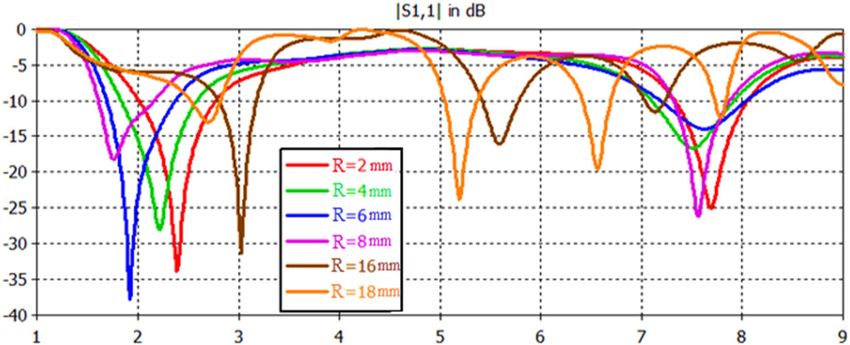
www.nature.com/scientificreports/
Figure 1. Antenna1 topology.
second-order Koch-like pre-fractal antennas and Euclidean antennas based on zig-zag and meander curves. The
performance of Euclidean antennas was at all times superior to Koch-like structures.
In10, a miniature dualband slotted patch antenna was simulated using a high-frequency full-wave electro-
magnetic simulator based on finite element routine. The projected antenna was manufactured employing LPKF
machine on fiberglass epoxy polymer resin material substrate, while the prototyped antenna performance was
determined in a typical far-field anechoic measurement chamber. The measurements of impedance bandwidths
of 12.26%, 8.24%, and 3.08% for frequency ranges of (14.3–16.2 GHz), (17.4–18.9 GHz) and (19.2–19.8 GHz)
respectively, were realized by this designed antenna prototype. In11, a new dualband printed antenna using a slot-
ted patch and a defected ground structure (DGS) was presented. By introducing an I-shaped slot into the patch
and defecting the ground plane, triple-mode resonance for accomplishing dualband operation with a particularly
wide bandwidth for the higher band was realized. The bandwidth measurements are 100 MHz (2.38–2.49 GHz)
and 2.94 GHz (3.4–6.34 GHz) for the minor and higher bands, correspondingly, that correspond satisfactorily
with the simulated results. Seljuk star-shaped slotted microstrip patch antenna was printed on a rectangular
shape glass epoxy FR4 substrate. Probe feed was employed in this antenna for multiband performance. The
multiband performance was investigated using dual-slot iterations. The projected antenna covers multiband
within 1.6–5.9 GHz frequency range12.A compact antenna consisting of an elliptical patch, a slotting line, and
a coaxial feedline is proposed in13. This design comprises a square patch and the capability to cover multiple
bands in a 1–15 GHz range. The simulation results of square patch with slotted line arrangement with different
slot size and with the modification in slot geometry of these different arrangements are presented. The slotted
square patch antenna is designed with an RT-Duroid substrate (εr = 2.22, h = 0.37 mm). Simulation results of
input reflection and polar radiation pattern are investigated. In14, a printed wide-slot antenna with wideband
frequency response has been experimentally investigated based on a modified L-shaped microstrip line for excit-
ing the square slot. It has a horizontal line, a square patch, and a vertical line. This antenna’s overall surface area
is 80 × 80 mm2 with a wide bandwidth of 3510 MHz and an applicable gain of 4.6 dBi that is suitable for many
wireless systems. A rectangular CPW folded slot antenna with a dualband response has been considered for the
Global Navigation Satellite Systems (GNSS) applications, as stated in15. This antenna can be operated for each
band of the GNSS Systems (L1-L2-L5-E5-E6-G1-G2) and its supreme gain has been within 0.2–2.9 dB range for
the band of 1200–1800 MHz. A circular slot antenna using offset microstrip-fed line has been presented in16.
This antenna shows dualband response under operating frequency bands of 1.83–2.73 GHz and 5.36–7.63 GHz
with impedance bandwidth of 39.5% and 34.9%, respectively. The bands have been valid for UMTS, PCS, ISM,
IMT- 2000, RFID, and Bluetooth in addition to WLAN applications. I n17, a group of small thin-wire antennas
based on Euclidean parts produced genetically had been presented. These small thin-wire antennas were electri-
cally in superior performance as compared with some sets of Sierpinski pre-fractal monopoles of the identical
electrical size at specified resonance.
In this paper, four printed slot antennas have been introduced based on Euclidean shapes to produce single,
dual and multiband frequencies. One of these printed slot antennas is circle based slot structure and the other is
octagon based slot structure. These antennas produce dual and single-band responses for each of them, respec-
tively. On the other hand, the other two printed slot antennas using a circle-based slot structure with an octagon
patch and an octagon-based slot structure with a circle patch are also presented. Parametric investigations are
done to examine the antenna responses as a function of microstrip feed length and patch radius length to acquire
the suitable electrical specifications. Accordingly, this study gives an impression that Euclidean antennas using
the printed slot approach can be competitors and alternatives to the fractal antennas without using complicated
structures, iteration and formulas.
Antenna design
All the depicted antennas are devices based on Euclidean slots with and without Euclidean patches etched on the
ground plane. All these structures have dimensions of a substrate (Wg × Lg) of 50 × 50 mm2. Single microstrip
feed coupled in the upper plane of the substrate has been employed in the antenna design. The first projected
printed slotted antenna is based on the circle shape, as shown in Fig. 1. The slot structure has a radius (R) of
20 mm. The microstrip feeder length (Lf) and width (Wf) are 23 and 3 mm, respectively.
Scientific Reports | (2021) 11:4415 | https://doi.org/10.1038/s41598-021-83772-2 2
Vol:.(1234567890)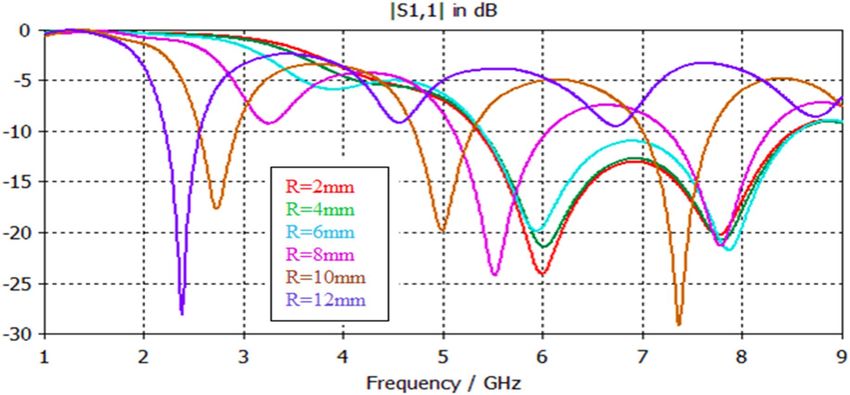
www.nature.com/scientificreports/

                                  Figure 2.  Antenna2 topology.

                                  Figure 3.  Antenna3 topology.

                                  Figure 4.  Antenna4 topology.

                                      Figure 2 shows the second printed slot antenna. This antenna is the same antenna depicted in Fig. 1, but a
                                  central octagonal patch has been added to the slot structure. The radius of the octagon patch is 18 mm. The values
                                  of Lf and Wf are 29 and 3 mm, respectively.
                                      Figure 3 shows the third printed slot antenna, which is based on an octagonal shape. The radius of the octago-
                                  nal slot is 15.67 mm. Lf and Wf magnitudes are 19 and 3 mm, respectively.
                                      Figure 4 depicts the fourth printed slot antenna. This antenna is the same antenna shown in Fig. 3, but a
                                  circular patch is added to the slot structure. The radius of the circular patch is 10 mm. The values of Lf and Wf
                                  are 17 and 3 mm, respectively.
                                      The substrate width and length of above Euclidean antennas are equal (Wg = Lg), and the following equations
                                  can be used to calculate the fundamental frequencies (F1, F2, F3, and F4) for Antenna1, Antenna2, Antenna3,
                                  and Antenna4:

Scientific Reports |   (2021) 11:4415 |                https://doi.org/10.1038/s41598-021-83772-2                                                 3

                                                                                                                                             Vol.:(0123456789)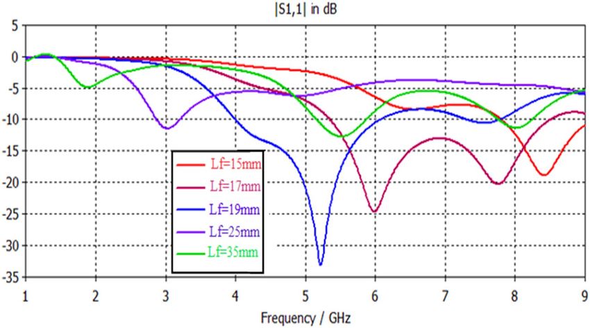
www.nature.com/scientificreports/
Figure 5. S11 response of Antenna1.
F1 (GHz) F2 (GHz) S11 (F1) dB S11 (F2) dB BW1 (GHz) BW2 (GHz)
2.7 8.3 − 50 − 29.2 0.41 0.34
Table 1. Electrical properties of Antenna1 response.
0.592c
F1 =
(1)
Lg εr 2+1
0.559c
F2 =
(2)
Lg εr 2+1
1.095c
F3 =
(3)
Lg εr 2+1
0.6c
F4 =
(4)
εr +1
Lg 2
where εr is the relative dielectric constant, and c is light speed. In terms of guided wavelength ( g ), the anticipated
antennas have substrate size of about 0.592 g × 0.592 g , 0.559 g × 0.559 g , 1.095 g × 1.095 g and 0.6 g × 0.6
g at their fundamental resonant frequencies of 2.7, 2.55, 5.2 and 2.74 GHz for Antenna1, Antenna2, Antenna3
and Antenna4 respectively. The guided wavelength has been computed based on18.
Results and discussion
Each printed slot antenna was simulated using Computer Simulation Technology (CST) electromagnetic simu-
lator. This simulator has accurate, capable computational solutions for antenna modeling and electromagnetic
performance investigation. Also, it has excellent possibilities to produce parametric studies for any antenna
dimension term or any resultant electrical parameter in good simulation running time.
For the first proposed printed circle based slot antenna illustrated in Fig. 1, its input reflection response is
determined within the swept frequency range from 1 to 9 GHz using a substrate of 4.4 dielectric constant and
1.6 mm dielectric thickness. As shown in Fig. 5, the circle based slot antenna offers a dual-band response using
a feedline length of 23 mm. Table 1 explains the electrical specifications of this antenna. This antenna is suitable
for WLAN and satellite systems.
The input reflection response for Antenna2 is shown in Fig. 6. This antenna offers multi-band responses
using a feedline with a length of 29 mm. The insertion of the octagon patch acts as an induction element which
affects the appearance of the resonance. It is based on an uncomplicated Euclidean shape that behaves like the
fractal or semi fractal antenna structures since it produces multiband responses that require specific formulas
Scientific Reports | (2021) 11:4415 | https://doi.org/10.1038/s41598-021-83772-2 4
Vol:.(1234567890)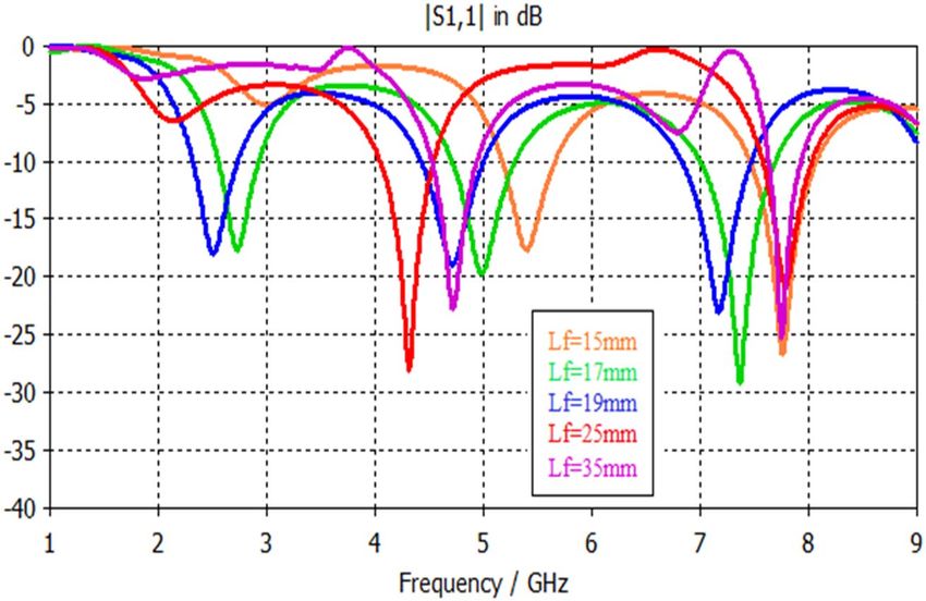
www.nature.com/scientificreports/
Figure 6. S11 response of Antenna2.
F1 (GHz) 2.55
F2 (GHz) 5
F3 (GHz) 8.7
S11 (F1) dB − 31.4
S11 (F2) dB − 17.4
S11 (F3) dB − 21.2
BW1 (GHz) 0.37
BW2 (GHz) 0.31
BW3 (GHz) 0.44
Table 2. Electrical properties of Antenna2 response.
and fractal topologies with specified i terations19. This antenna is appropriate for WLAN and satellite applications.
The magnitudes of frequency bands, their S11 values and bandwidths are shown in Table 2.
The S11 response of printed octagon based slot antenna (Antenna3) depicted in Fig. 3 can be observable from
Fig. 7. The octagon based slot antenna offers a single band resonance with a wide bandwidth of 2 GHz suitable
for WiMAX applications. Table 3 summarizes its performance.
Lastly, the input reflection response of antenna based on an octagonal with circular patch (Antenna4) is
depicted in Fig. 8. This antenna exhibits a multiband response, which is appropriate for WiMAX, WLAN, and
satellite applications. As seen from this graph, the patch’s adding acts as a perturbation element; this affects the
appearance of multiple band resonances with lower bandwidths and input reflection values compared with
Antenna3. Table 4 explains the details of Antenna4 response concerning resonant frequencies, input reflection
values at these band frequencies as well as its bandwidths.
The IEEE gain magnitudes in units of dBi in the first elementary band have been evaluated in Figs. 9, 10, 11,
12 for Antennas1, 2, 3 and 4 correspondingly. These gain values are tolerable for typical wireless communication
applications in use within these design frequencies. As frequency increases, the gain value is mostly increased
primarily within (0–7) dBi.
In Figs. 13, 14, 15, 16, magnetic intensity distributions are depicted based on the first (fundamental) reso-
nance for each designed antenna to investigate the antennas’ electromagnetic behaviors. The red color signposts
the maximum magnetic intensity value, while the green color stands for the minimum. Namely, the effective
areas are in regions with the highest magnetic intensity distributions. All distributions have been patterned
symmetrically, and maximum magnetic intensity values are concentrated in the feed line, slot boundaries, and
nearby regions. Based on these findings, feedline length and patch scaling aspects are adopted as useful factors
in the parametric studies in Sect. 4 in this paper.
The proposed printed slot antennas in this study have been compared with other published papers in the
literature regarding fractal antennas. Accordingly, Table 5 shows several performance parameters of several
single-band, dual-band and multiband antennas manufactured by different fractal design approaches in reported
studies. Among these parameters, a specific highlighting has focused on the antenna size, design principle, sub-
strate material, resonances, and gain offered by the proposed antenna. Regardless of the number of bands and
Scientific Reports | (2021) 11:4415 | https://doi.org/10.1038/s41598-021-83772-2 5
Vol.:(0123456789)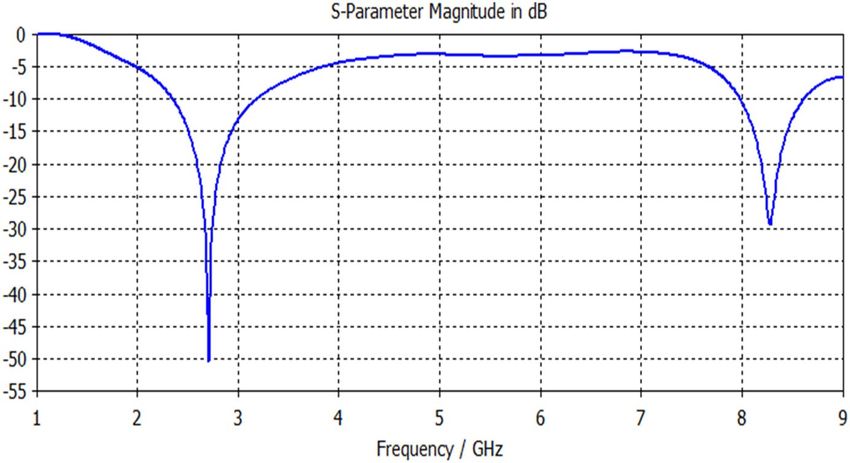
www.nature.com/scientificreports/
Figure 7. S11 response of Antenna3.
F1 (GHz) S11 (F1) dB BW (GHz)
5.2 − 33 2
Table 3. Electrical specification of Antenna3.
Figure 8. S11 response of Antenna4.
resonances, the projected printed slot antennas based on Euclidean geometries have competitive miniaturization
and gain as compared w ith20–27. Also, the printed slot antenna designs presented in this paper have significantly
simpler topologies and feeding methods t han20–27.
Parametric analyses
Simulation results, shown in Figs. 17, 18, 19, 20, 21, 22, disclose that the modeled antenna can exhibit single,
dual-band and multiband responses within the prescribed sweep frequency. This makes the antenna structure
suitable for different wireless applications. In this case, simulation results show that the input reflections affected
by two parameters; the feedline length and scaling factor of Euclidean patch structure. Parametrical investiga-
tions are achieved to discover the effects of these two parameters on the antenna performance with summarized
electrical parameters.
Scientific Reports | (2021) 11:4415 | https://doi.org/10.1038/s41598-021-83772-2 6
Vol:.(1234567890)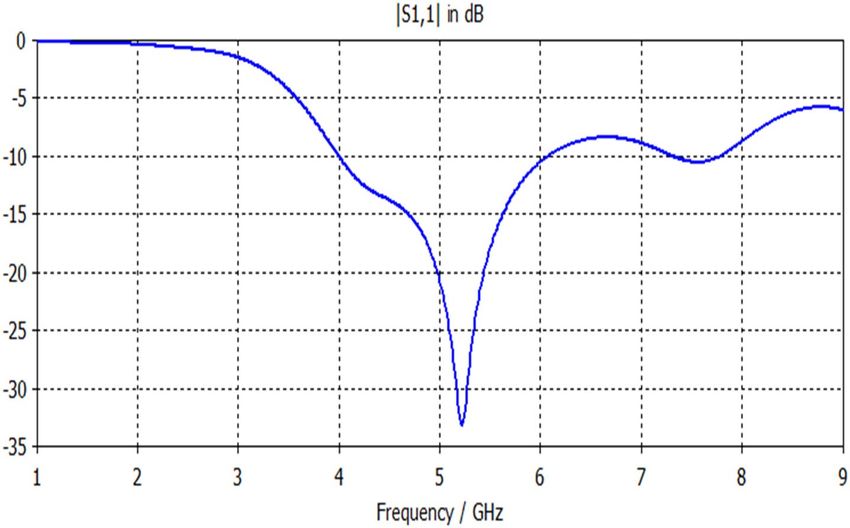
www.nature.com/scientificreports/
F1 (GHz) 2.74
F2 (GHz) 5
F3 (GHz) 7.4
S11 (F1) dB − 17.6
S11 (F2) dB − 19.7
S11 (F3) dB − 29
BW1 (GHz) 0.37
BW2 (GHz) 0.6
BW3 (GHz) 0.68
Table 4. Electrical properties of Antenna 4.
Figure 9. Gain result for Antenna1.
Effect of feed length. The feed line stands for a critical constituent that should be adjusted to work appro-
priately with the antenna. The microstrip feeder has been employed since it provides ease of fabrication and
simplicity in modeling and impedance matching. Figures 17, 18, 19, 20 illustrate the projected antennas’ input
reflection results with respect to feedline length limitation. The feeder length significantly affects the antenna’s
frequency response in terms of resonances, number of bands, input reflection, and impedance bandwidth. For
ranged feedline length from 15 to 35 mm, these antennas have potentially single, dual and multi-band responses
with interesting features. Figure 17 demonstrates the input reflection response of the antenna depicted in Fig. 1
with feedline length as a parameter. Figure 18 illustrates the S11 responses of the antenna depicted in Fig. 2
with feedline length as a parameter. The parametrical responses of Fig. 17 have shown only single and dualband
responses, while in Fig. 18, multiband responses are recognizably based on adopted feedline length. Tables 6, 7
clarify all electrical details of parametrical responses of Figs. 17, 18, respectively.
Figure 19 demonstrates the antenna’s various input reflection responses in Fig. 3 with feedline length as a
parameter. The parametrical responses of Fig. 19 have exposed only single and dualband responses. Table 8
explains their electrical specifications. On the other hand, Fig. 20 and Table 9 show the feasible multiband
responses for Antenna4 topology.
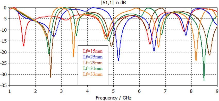
Effect of antenna patch radius variation. Figure 21 and Table 10 depict the S11 results of Antenna2
topology presented in Fig. 2 with respect to antenna patch radius variation. For feedline lengths of 25 mm, the
antenna has feasibly dual and multiband responses with interesting features. Figure 22 and Table 11 depict the
proposed antenna’s input reflection results shown in Fig. 4 with respect to antenna patch radius variation. For
Scientific Reports | (2021) 11:4415 | https://doi.org/10.1038/s41598-021-83772-2 7
Vol.:(0123456789)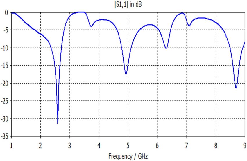
www.nature.com/scientificreports/

                                            Figure 10.  Gain result for Antenna2.

                                            Figure 11.  Gain result for Antenna3.

                                            feedline lengths of 17 mm, the antenna has possibly single, dual and multiband responses with interesting fea-
                                            tures and wider impedance bandwidths than in Fig. 21.

                                            Measurement
                                            Figures 23, 24, 25, 26 illustrate the slotted ground structure and microstrip feed views of the fabricated prototypes
                                            of the designed Antennas1, 2, 3, and 4 employing LPKF machine. The measurements of S11 results have been
                                            done by Anritsu Vector Network Analyzer. The measured and simulated results of S11 responses are in accept-
                                            able agreement as shown in Figs. 27, 28, 29, 30. There are tolerable differences and ripples in the measurements
                                            as compared with the simulations due to manufacturing conditions, soldering and measurement environment.
                                            These differences are also related to a commercially cost-effective FR4 substrate used in this study for prototyp-
                                            ing the printed slot antenna models. The substrate loss tangent becomes more in effect at the greater frequencies
                                            and results in more losses.
                                                Figures 31, 32, 33, 34 describe the simulated and measured far-field radiation patterns for the total electric
                                            field in the x–y, x–z, and y–z planes for Antennas1, 2, 3, and 4, respectively, at their fundamental operating fre-
                                            quency. Both simulated and measured radiation patterns are in good agreement. For all radiation patterns, the
                                            x–y plane (θ = 90o, φ is variable), the x–z plane (φ = 0o, θ is variable) and the y–z plane (φ = 90°, θ is variable), they
                                            are all of bidirectional radiations patterns with tolerable performances and applicable for wireless applications.

          Scientific Reports |   (2021) 11:4415 |                 https://doi.org/10.1038/s41598-021-83772-2                                                        8

Vol:.(1234567890)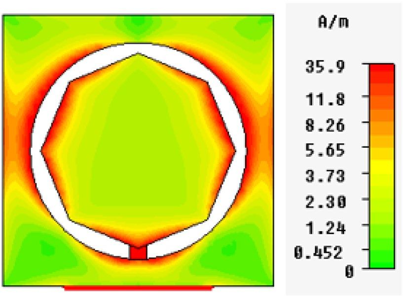
www.nature.com/scientificreports/

                                  Figure 12.  Gain result for Antenna4.

                                  Figure 13.  Magnetic intensity distributions for Antenna1 at the fundamental resonance of 2.7 GHz.

                                  Figure 14.  Magnetic intensity distributions for Antenna2 at the fundamental resonance of 2.55 GHz.

Scientific Reports |   (2021) 11:4415 |               https://doi.org/10.1038/s41598-021-83772-2                                             9

                                                                                                                                        Vol.:(0123456789)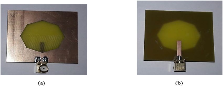
www.nature.com/scientificreports/
Figure 15. Magnetic intensity distributions for Antenna3 at the fundamental resonance of 5.2 GHz.
Figure 16. Magnetic intensity distributions for Antenna4 at the fundamental resonance of 2.74 GHz.
Refs. Size (mm2) Design principle Material Resonances (GHz) Gain (dBi)
20
50 × 50 Cantor fractal-based printed slot antenna FR4 2.4/5.8 3.2/4.3
21
70 × 70 Dual reverse-arrow fractal FR4 2.4 2.3
22 A dielectric resonator loaded
100 × 100 FR4 1.42/2.61/3.65/4.93/6.15 2.2/2.2/3.4/4.4/4.0
Fractal slot loop antenna
23
55 × 60 Dragonfly fractal Roger 5880 2.6/4.4/8.7 3.6/5.5/7.3
24
97.48 × 80 CPW Fed Fractal Antenna FR4 2.39/3.77 4.56, 1.09
25
85 × 85 Microstrip fractal antenna FR4 2.1/3.8/4.8 1.4/4.8/2.9
26
50.5 × 83.5 Perturbed Sierpinski monopole gasket Arlon 1.1/3.4/5.8 1.74/5.95/4.22
27
78 × 38 Minkowski Fractal Antenna FR4 1.54/1.88 …
Ant.1 50 × 50 Euclidean printed slot antenna FR4 2.7/8.3 3.2/7.1
Ant.2 50 × 50 Euclidean printed slot antenna FR4 2.55/5/8.7 3.1/5.5/6.4
Ant.3 50 × 50 Euclidean printed slot antenna FR4 5.2 4.2
Ant.4 50 × 50 Euclidean printed slot antenna FR4 2.74/5/7.4 3/4.3/7.4
Table 5. Comparison with other testified antennas in the literature.
Conclusion
In this paper, four printed slot antennas have been introduced based on simple topologies of Euclidean slots
with and without Euclidean patches. One of these antennas is a circle slot based structure with and without an
octagon patch. These antennas produce dual and single-band responses for each of them, respectively. On the
other hand, printed slot antennas using octagon slot based structure with and without circular patch are also
presented. These antennas can produce dual and multiband responses with adequate performances. Parametrical
predictions based on feedline length and radius of adopted patches on antenna performance can be employed
to discover the consequences of these two parameters on the antenna performance with applicable electrical
specifications. Printed slot antennas with Euclidean patches have potential multiband responses more than ones
without Euclidean patches. However, printed slot antennas without Euclidean patches have wider impedance
bandwidths, especially for single-band responses than ones with Euclidean patches. The proposed topologies of
Scientific Reports | (2021) 11:4415 | https://doi.org/10.1038/s41598-021-83772-2 10
Vol:.(1234567890)www.nature.com/scientificreports/
Figure 17. S11 responses of the antenna structure depicted in Fig. 1 with a feedline length as a parameter.
Figure 18. S11 responses of the antenna structure depicted in Fig. 2 with a feedline length as a parameter.
printed slot antennas are simpler than reported fractal antennas with competitive electrical parameters. Accord-
ingly, these designed printed slot antennas can be incorporated within many portable and fixed wireless systems.
Recommendation
The current work comprises of design and fabrication of printed slot antennas based on Euclidean structures for
the GHz region. Many antennas for the THz region are being designed with improved Q-factor, which octagonal
or hexagonal micro antennas may not display. However, different Euclidean structures can be investigated as a
feasible future work to fix this issue.
Scientific Reports | (2021) 11:4415 | https://doi.org/10.1038/s41598-021-83772-2 11
Vol.:(0123456789)www.nature.com/scientificreports/
Figure 19. S11 responses of the antenna structure depicted in Fig. 3 with feedline length as a parameter.
Figure 20. S11 responses of Antenna4 topology using a feedline length as a parameter.
Scientific Reports | (2021) 11:4415 | https://doi.org/10.1038/s41598-021-83772-2 12
Vol:.(1234567890)www.nature.com/scientificreports/
Figure 21. S11 responses for Antenna2 topology with respect to radius variations using a feedline length of
25 mm.
Figure 22. S11 responses based on Antenna4 patch radius variations using a feedline length of 17 mm.
Feed length (mm) F1 (GHz) F2 (GHz) S11 (F1) dB S11 (F2) dB BW1 (GHz) BW2 (GHz)
15 5 … − 22 … 2.1 …
25 2.42 7.76 − 38.4 − 31.5 0.76 0.71
29 2 6.6 − 42.3 − 18.9 0.65 0.7
31 1.8 6.2 − 18.1 − 18.1 0.47 0.66
33 1.65 6 − 11.2 − 15.3 0.18 0.65
Table 6. Electrical properties of Antenna1 using a feedline length as a parameter.
Scientific Reports | (2021) 11:4415 | https://doi.org/10.1038/s41598-021-83772-2 13
Vol.:(0123456789)www.nature.com/scientificreports/
Feed length (mm) 15 25 29 31 33
F1 1.54 2.6 2.55 2.5 2.4
F2 4.7 5.2 5 3.5 3.4
F3 6.4 6.5 … 4.8 4.7
F4 7.72 7.7 8.7 6.8 6.7
F5 … … … 8.4 8.1
S11 (F1) dB − 17.2 − 13.1 − 31.6 − 21.1 − 13
S11 (F2) dB − 13 − 24.1 − 17.6 − 12.8 − 22
S11 (F3) dB − 16.3 − 19.6 … − 15 − 14
S11 (F4) dB − 10.7 − 12.6 − 21.2 − 12.4 − 17.6
S11 (F5) dB … … … − 32.7 − 24
BW1 (GHz) 0.15 0.32 0.36 0.3 0.2
BW2 (GHz) 0.28 0.32 0.3 0.1 0.15
BW3 (GHz) 0.27 0.31 … 0.26 0.26
BW4 (GHz) 0.1 0.1 0.46 0.11 0.21
BW5 (GHz) … … … 0.4 0.3
Table 7. Electrical properties of Antenna2 with respect to a feedline length as a parameter.
Feed length (mm) F1 (GHz) F2 (GHz) S11 (F1) dB S11 (F2) dB BW1 (GHz) BW2 (GHz)
15 8.4 … − 19 … 1.2 …
17 7 … − 24 … 3.13 …
19 5.11 7.6 − 33.2 − 10.8 2 0.38
25 3 … − 11.5 … 0.31 …
35 5.5 8 − 12.8 − 11.7 0.7 0.44
Table 8. Electrical properties of Antenna3 with a feedline length as a parameter.
Feed length BW3
(mm) F1 (GHz) F2 (GHz) F3 (GHz) S11 (F1) dB S11 (F2) dB S11 (F3) dB BW1 (GHz) BW2 (GHz) (GHz)
15 5.4 7.7 … − 17.7 − 26.8 … 0.46 0.62 …
17 2.7 5 7.4 − 18.2 − 20 − 29.3 0.38 0.6 0.64
19 2.5 4.7 7.2 − 18.3 − 19 − 23.2 0.41 0.58 0.65
25 4.3 7.8 … − 28.3 − 21 … 0.47 0.48 …
35 4.7 7.7 … − 22.7 − 26 … 0.4 0.33 …
Table 9. Electrical properties of Antenna4 topology using a feedline length as a parameter.
Patch radius (mm) 2 4 6 8 16 18
F1 (GHz) 2.4 2.2 2 1.8 3 2.6
F2 (GHz) 7.6 7.5 7.6 7.6 5.6 5.2
F3 (GHz) … … … … 7.1 6.5
F4 (GHz) … … … … … 7.7
S11 (F1) dB − 34 − 28 − 38 − 18.5 − 31.1 − 13.3
S11 (F2) dB − 25 − 16.4 − 14.2 − 26.5 − 16.4 − 24.3
S11 (F3) dB … … … … − 12 − 19.5
S11 (F4) dB … … … … … − 12.8
BW1 (GHz) 0.75 0.75 0.7 0.58 0.37 0.32
BW2 (GHz) 0.73 0.76 0.77 0.5 0.36 0.3
BW3 (GHz) … … … … 0.21 0.36
BW4 (GHz) … … … … … 0.14
Table 10. Electrical parameter details for Antenna2 with respect to patch radius variations using a feedline
length of 25 mm.
Scientific Reports | (2021) 11:4415 | https://doi.org/10.1038/s41598-021-83772-2 14
Vol:.(1234567890)www.nature.com/scientificreports/
Patch radius (mm) 2 4 6 8 10 12
F1 (GHz) 7 7 7 5.5 2.7 2.3
F2 (GHz) … … … 7.8 5 …
F3 (GHz) …. …… …… …… 7.3 …
S11 (F1) dB − 23.6 − 21.3 − 21.3 − 24.3 − 17.5 − 28
S11 (F2) dB … … … − 21.1 − 20 …
S11 (F3) dB … … … … − 29.3 …
BW1 (GHz) 3.13 3.13 3.13 0.92 0.33 0.35
BW2 (GHz) … … 0.98 0.62 …
BW3 (GHz) … … … 0.65 …
Table 11. Electrical details of Antenna4 topology with respect to patch radius variations using a feedline
length of 17 mm.
Figure 23. Manufactured prototype of Antenna1 (a) ground plane, (b) microstrip feed plane.
Figure 24. Manufactured prototype of Antenna2 (a) ground plane, (b) microstrip feed plane.
Figure 25. Manufactured prototype of Antenna3 (a) ground plane, (b) microstrip feed plane.
Scientific Reports | (2021) 11:4415 | https://doi.org/10.1038/s41598-021-83772-2 15
Vol.:(0123456789)www.nature.com/scientificreports/
Figure 26. Manufactured prototype of Antenna4 (a) ground plane, (b) microstrip feed plane.
Figure 27. Simulated and measured S11 responses of Antenna1.
Figure 28. Simulated and measured S11 responses of Antenna2.
Scientific Reports | (2021) 11:4415 | https://doi.org/10.1038/s41598-021-83772-2 16
Vol:.(1234567890)www.nature.com/scientificreports/
Figure 29. Simulated and measured S11 responses of Antenna3.
Figure 30. Simulated and measured S11 responses of Antenna4.
Scientific Reports | (2021) 11:4415 | https://doi.org/10.1038/s41598-021-83772-2 17
Vol.:(0123456789)www.nature.com/scientificreports/
Figure 31. Simulated and measured radiation patterns of Antenna1 at the fundamental frequency of 2.7 GHz.
Figure 32. Simulated and measured radiation patterns of Antenna2 at the fundamental frequency of 2.55 GHz.
Scientific Reports | (2021) 11:4415 | https://doi.org/10.1038/s41598-021-83772-2 18
Vol:.(1234567890)www.nature.com/scientificreports/
Figure 33. Simulated and measured radiation patterns of Antenna3 at the fundamental frequency of 5.2 GHz.
Figure 34. Simulated and measured radiation patterns of Antenna4 at the fundamental frequency of 2.74 GHz.
Scientific Reports | (2021) 11:4415 | https://doi.org/10.1038/s41598-021-83772-2 19
Vol.:(0123456789)www.nature.com/scientificreports/
Received: 3 July 2020; Accepted: 8 February 2021
References
1. Shandal, S., Mezaal, Y. S., Kadim, M. & Mosleh, M. New compact wideband microstrip antenna for wireless applications. Adv.
Electromag. 7(4), 85–92 (2018).
2. Pandey, A. Practical Microstrip and Printed Antenna Design (Artech House, Norwood, 2019).
3. Qian, J. F., Chen, F. C., Xiang, K. R. & Chu, Q. X. Resonator-Loaded multi-band microstrip slot antennas with bidirectional radia-
tion patterns. IEEE Trans. Antennas Propag. 67(10), 6661–6666 (2019).
4. Abdulkareem, S. F. & Mezaal, Y. S. Applications of fractal and quasi fractal geometries in slot antenna design: a review. J. Mech.
Continua Math. Sci. 14(4), 216–238 (2019).
5. Cao, Y. F., Cheung, S. W. & Yuk, T. I. A multiband slot antenna for GPS/WiMAX/WLAN systems. IEEE Trans. Antennas Propag.
63(3), 952–958 (2015).
6. Rmili, H., Oueslati, D., Trad, I. B., Floch, J. M., Dobaie, A., & Mittra, R. Investigation of a random-fractal antenna based on a
natural tree-leaf geometry. Int. J. Antennas Propag. 2017 (2017)
7. Kaur, R., Singh, S. & Kumar, N. A review of various fractal geometries for wireless applications. Int. J. Electr. Electron. Eng. 2(1),
34–36 (2015).
8. Yassen, M. T., Hussan, M. R., Hammas, H. A., Salim, A. J. & Ali, J. K. Design of compact dual-band fractal monopole antenna with
virtually extended ground plane. Adv. Electromag. 7(4), 19 (2018).
9. Pantoja, M. F. et al. GA design of wire pre-fractal antennas and comparison with other euclidean geometries. IEEE Antennas Wirel.
Propag. Lett. 2, 238–241 (2003).
10. Habib Ullah, M., Islam, M.T., Ahsan, M.R., Mandeep, J.S. & Misran, N.A dual band slotted patch antenna on dielectric material
substrate. Int. J. Antennas Propag. 2014 (2014).
11. Wu, C. M., Syu, J. W. & Liu, W. C. Dual-band slotted patch antenna with defective ground for WLAN/WiMAX applications. Prog.
Electromag. Res. 53, 1–6 (2015).
12. Kumar, S. & Chandra, D.. Multiband star shape slotted micro-strip patch antenna design for wireless application. Int. J. Electron.
Electr. Eng. 3(5) (2015).
13. Vyas, S. R. K. Compact elliptical multiband slotted patch antenna with defective ground structure. Int. J. Sci. Eng. Res. 6(10),
119–122 (2015).
14. Sung, Y. A printed wide-slot antenna with a modified L-shaped microstrip line for wideband applications. IEEE Trans. Antennas
Propag. 59(10), 3918–3922 (2011).
15. Reha, A. & Bouchouirbat, M. A dual-band rectangular CPW folded slot antenna for GNSS applications. Int. J. Adv. Res. Electr.
Electron. Instrum. Eng. 3(8), 11055–11061 (2014).
16. Ooi, P. C. & Selvan, K. T. A dual-band circular slot antenna with an offset microstrip-fed line for PCS, UMTS, IMT-2000, ISM,
Bluetooth, RFID and WLAN applications. Prog. Electromag. Res. 16, 1–10 (2010).
17. Pantoja, M. F. et al. GA design of small thin-wire antennas: comparison with Sierpinsky-type prefractal antennas. IEEE Trans.
Antennas Propag. 54(6), 1879–1882 (2006).
18. Waterhouse, R. Microstrip Patch Antennas: A Designer’s Guide: A Designer’s Guide (Springer, Berlin, 2003).
19. Anguera, J. et al. Fractal antennas: an historical perspective. Fractal Fractional 4(1), 3 (2020).
20. Ali, J. K. et al. Cantor fractal-based printed slot antenna for dual-band wireless applications. Int. J. Microw. Wirel. Technol. 8(2),
263–270 (2016).
21. Orazi, H. & Soleimani, H. Miniaturisation of the triangular patch antenna by the novel dual-reverse-arrow fractal. IET Microwaves
Antennas Propag. 9(7), 627–633 (2014).
22. Dhar, S., Patra, K., Ghatak, R., Gupta, B. & Poddar, D. R. A dielectric resonator-loaded minkowski fractal-shaped slot loop hep-
taband antenna. IEEE Trans. Antennas Propag. 63(4), 1521–1529 (2015).
23. Kumar, A. & Pharwaha, A. P. S. Triple band fractal antenna for Radio Navigation and fixed satellite services using Dragonfly
optimization. Adv. Electromag. 8(3), 43–49 (2019).
24. Kantharia, M. et al. High gain flexible cpw fed fractal antenna for Bluetooth/WLAN/WPAN/WiMAX applications. Prog. Electromag.
Res. 79, 87–93 (2018).
25. Barreto, E. L. & Mendonça, L. M. A new triple band microstrip fractal antenna for C-band and S-band applications. J. Microwaves,
Optoelectron. Electromag. Appl. 15(3), 210–224 (2016).
26. MM, A. K., Patnaik, A., & Christodoulou, C. G. ,. Design and testing of a multifrequency antenna with a reconfigurable feed. IEEE
Antennas Wirel. Propag. Lett. 13, 730–733 (2014).
27. Abdullah, N., Arshad, M. A., Mohd, E., and Hamzah, S. A. Design of Minskowsi fractal antenna for dual band application. In 2008
International Conference on Computer and Communication Engineering 352–355 (IEEE, 2008).
Acknowledgements
The author of this research article highly appreciates Prof. Dr. Jawad K. Ali from Electrical Engineering Depart-
ment, University of Technology in Iraq for his scientific advices. In addition, the author highly thanks the han-
dling editor and reviewers for their advantageous review comments.
Author contributions
Y.S.M wrote and revised the entire paper.
Competing interests
The author declares no competing interests.
Additional information
Correspondence and requests for materials should be addressed to Y.S.M.
Reprints and permissions information is available at www.nature.com/reprints.
Publisher’s note Springer Nature remains neutral with regard to jurisdictional claims in published maps and
institutional affiliations.
Scientific Reports | (2021) 11:4415 | https://doi.org/10.1038/s41598-021-83772-2 20
Vol:.(1234567890)www.nature.com/scientificreports/
Open Access This article is licensed under a Creative Commons Attribution 4.0 International
License, which permits use, sharing, adaptation, distribution and reproduction in any medium or
format, as long as you give appropriate credit to the original author(s) and the source, provide a link to the
Creative Commons licence, and indicate if changes were made. The images or other third party material in this
article are included in the article’s Creative Commons licence, unless indicated otherwise in a credit line to the
material. If material is not included in the article’s Creative Commons licence and your intended use is not
permitted by statutory regulation or exceeds the permitted use, you will need to obtain permission directly from
the copyright holder. To view a copy of this licence, visit http://creativecommons.org/licenses/by/4.0/.
© The Author(s) 2021
Scientific Reports | (2021) 11:4415 | https://doi.org/10.1038/s41598-021-83772-2 21
Vol.:(0123456789)You can also read