Design of a Multi-Band Microstrip Textile Patch Antenna for LTE and 5G Services with the CRO-SL Ensemble - MDPI
←
→
Page content transcription
If your browser does not render page correctly, please read the page content below
applied
           sciences
Article
Design of a Multi-Band Microstrip Textile Patch
Antenna for LTE and 5G Services with the
CRO-SL Ensemble
Carlos Camacho-Gomez, Rocio Sanchez-Montero * , Diego Martínez-Villanueva,
Pablo-Luís López-Espí and Sancho Salcedo-Sanz
 Department of Signal Processing and Communications, Escuela Politécnica Superior, Universidad de Alcalá,
 Campus Universitario, Ctra. de Madrid a Barcelona km 33.600, 28805 Alcalá de Henares, Spain;
 carlos.camacho@uah.es (C.C.-G.); diego.martinezv@edu.uah.es (D.M.-V.); pablo.lopez@uah.es (P.-L.L.-E.);
 sancho.salcedo@uah.es (S.S.-S.)
 * Correspondence: rocio.sanchez@uah.es; Tel.: +34-91-8856660

 Received: 17 January 2020; Accepted: 7 February 2020; Published: 9 February 2020

 Featured Application: A novel textile U-shaped with concentric annular slot antenna prototype for
 LTE and 5G services has been described. In the ground plane, a meander slot has been introduced
 to reduce the antenna dimensions. A new multi-method metaheuristic algorithm, the Coral Reefs
 Optimization with Substrate Layer CRO-SL, has been used to optimize the antenna parameters
 and improve its performance in the frequency bands of interest.

 Abstract: A textile multi-band antenna for LTE and 5G communication services, composed by a
 rectangular microstrip patch, two concentric annular slots and a U-Shaped slot, is considered in this
 paper. In the ground plane, three sleeved meanders have been introduced to modify the surface
 current distribution, leading to a bandwidth improvement. The U-Shaped slot, the dual circular
 slots, and the meanders shape have been optimized by means of the Coral Reefs Optimization
 with Substrate Layer algorithm (CRO-SL). This population-based meta-heuristic approach is a kind
 of ensemble algorithm for optimization (multi-method), in which different search operators are
 considered within the algorithm. We show that the CRO-SL is able to obtain a robust multi-band
 textile antenna, including LTE and 5G frequency bands. For the optimization process, the CRO-SL is
 guided by means of a fitness function obtained after the antenna simulation by a specific simulation
 software for electromagnetic analysis in the high frequency range.

 Keywords: antenna design; constrained optimization problems; coral reefs optimization algorithm;
 meta-heuristics

1. Introduction
     In the last decade, a large variety of wireless enabled portable devices such as smartphones,
tablets or laptops have been introduced. The implementation of new mobile technologies further
increases the bandwidth requirements of wireless systems in order to cover recently allocated LTE and
5G frequency bands [1]. Recent research works have allowed us to develop the design of antennas
using textile materials in the substrate, leading to devices called “wearable antennas” [2]. One of
the main advantages of the antennas based on textile materials is that they can be manufactured
using smart fabric and interactive textile systems [3], in which unobtrusive integration of electronic
components increases functionality of the garment [4,5].
     Recently, the implementation of different kind of antennas in wearables has been massive [6–9].
Microstrip patch antennas are frequently used in textile materials because of their many advantages,

Appl. Sci. 2020, 10, 1168; doi:10.3390/app10031168                              www.mdpi.com/journal/applsci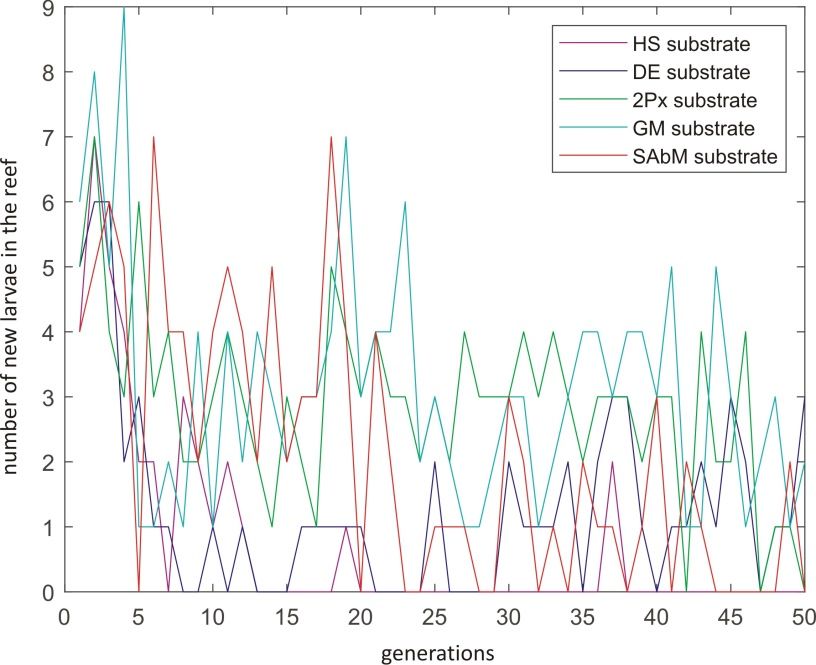
Appl. Sci. 2020, 10, 1168                                                                           2 of 17

such as low profile, light weight, and conformity. However, these kind of antennas suffer from
important issues in their design process (precise value and model of fabric dielectric constant for
simulations, difficulty to glue metallic parts to textile materials, bending and moisture influence in
antenna performance, etc.), causing severe limitations in their practical applications. This fact is even
more dramatic in the frequency bands of modern communication systems based on LTE and 5G
technologies. The number of parameters to be tuned in order to make the antenna feasible for working
in LTE and 5G applications is usually very high. In these cases, classical optimization methods are
no longer suitable, and the employment of advanced optimization algorithms (mainly meta-heuristic
approaches, among others) has been shown to be very useful for antenna design [10–14].
     In this paper, we propose a new model of microstrip textile patch antenna, a multi-band device that
can be tuned for LTE and 5G services, among others. Specifically, the proposed antenna is composed
by a rectangular microstrip patch with two concentric annular slots and a U-Shaped slot, with sleeved
meanders introduced in the ground plane to modify the surface current distribution, leading to a
bandwidth improvement [15–17]. This original shape allows the antenna to work accurately in several
frequency bands, including LTE and 5G communication services. On the other hand, this specific
shape also leads to a hard optimization problem, with a high number of real variables and constraints
to be taken into account. Moreover, the proposed antenna has been simulated considering a wearable
substrate, which makes the direct designing process even more difficult.
     A meta-heuristic algorithm for optimization is then considered in order to obtain a good design of
the antenna, with excellent properties of bandwidth in all the considered frequency bands. Therefore,
we propose to use a version of the Coral Reefs Optimization (CRO) algorithm [18]—in this case,
the version with the substrate layer (CRO-SL) approach [19]. The CRO is an evolutionary type
algorithm which simulates all the processes occurring in a real coral reef in order to carry out the
optimization of a given system (the textile antenna considered in this work in this case). The CRO-SL
version has been successfully applied to a number of optimization problems [19], and it is able to
combine different search patterns or strategies within a single population of potential solutions. In this
case, we will show how this optimization scheme is able to obtain excellent results in the optimization
process of the proposed antenna, tuning it for its use in LTE and 5G communication systems. In the
experimental section of the paper, we detail the antenna design process and its simulation with specific
software in order to evaluate the potential of the CRO-SL in this design problem.
     The rest of the paper is structured in the following way: the next section presents in detail the
proposed antenna design, characteristics, and variables to be optimized. Section 3 describes the
CRO-SL algorithm used to optimize the textile antenna for LTE and 5G systems. Section 4 shows
the experiments carried out to optimize the antenna, and the results obtained in simulation of the
optimized device. Finally, Section 5 closes the paper with some final remarks on the research carried
out in this paper.

2. Antenna Model
     The proposed microstrip patch antenna is shown in Figure 1. It combines several key features to
provide the desired operational performance at different frequencies, including LTE and 5G bands.
Specifically, the proposed design comprises a rectangular microstrip patch with two concentric annular
slots. Each ring has four spikes within it. This type of patch antenna is inspired by different works
previously presented in the literature [20–24]. Additionally, the design contains a U-shaped aperture
of rectangular slots to obtain the resonant frequency for the LTE band. U-slot patch antennas are well
known mainly for their wide-band characteristics and are capable of providing other advantages,
including dual band and triple-band operations, due to their ability to be implemented with other
patch antenna shapes, such as circular, triangular, or rectangular shapes [25]. The proposed antenna
is completed with three meander slots at the bottom of the ground plane, according to the study
in reference [26]. Table 1 shows the variables involved in antenna design and the variable ranges
considered in this case.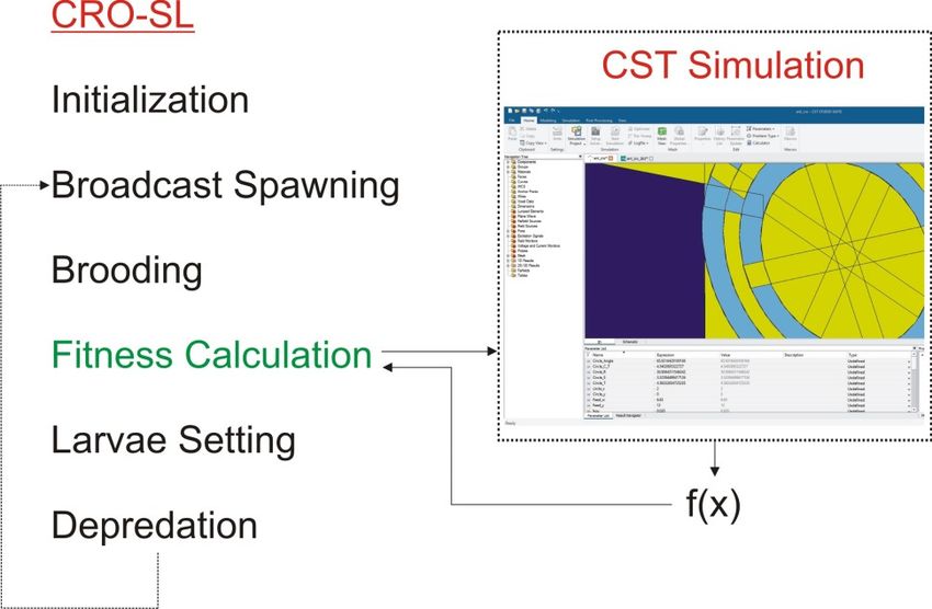
Appl. Sci. 2020, 10, 1168                                                                                       3 of 17
Appl. Sci. 2020, 10, x FOR PEER REVIEW                                                                               3 of 17

                     y
                              x

                                  (a)                                                       (b)

                                                                                            (d)
                                  (c)

     Figure 1.1.Variables
       Figure     Variablesdescription
                              description of
                                           of the proposed
                                                  proposed antenna.
                                                             antenna.(a)
                                                                       (a)Antenna
                                                                            Antennatop
                                                                                     top    view
                                                                                         view    U-shaped
                                                                                               U-shaped       variable
                                                                                                           variable
       description;
     description;  (b)(b)antenna
                          antennatop
                                  topview
                                       view the
                                             the annular
                                                 annular patch
                                                          patchvariable
                                                                variabledescription; (c)(c)
                                                                          description;   detail description
                                                                                            detail           of the
                                                                                                   description   of the
       variables
     variables ininthe
                     thetop
                          topview
                              viewof
                                   ofthe
                                      theantenna
                                          antenna that
                                                   that have
                                                        havebeen
                                                              beenused
                                                                   usedininthe
                                                                            theoptimization
                                                                                optimization  process; (d)(d)
                                                                                                process;   antenna
                                                                                                              antenna
       ground
     ground    plane.
             plane.

         Note that the optimization of the proposed antenna in order to be operational in the desired
      Note that the optimization of the proposed antenna in order to be operational in the desired
   frequencies is a hard problem in which metaheuristic algorithms can obtain good results. Note also
frequencies is a hard problem in which metaheuristic algorithms can obtain good results. Note also
   that the objective function must be calculated starting from the antenna simulation for a given set of
that the objective function must be calculated starting from the antenna simulation for a given set of
   antenna parameters. Thus, the hybridization of a simulation software with a meta-heuristic algorithm
antenna   parameters. Thus, the hybridization of a simulation software with a meta-heuristic algorithm
   is necessary to tackle the optimization of this antenna. Specifically, the CRO-SL algorithm will be used
is as
   necessary   tosince
      optimizer,  tackle
                       its the  optimization
                           characteristics     of this antenna.
                                           of multi-method  with Specifically,  theoperators
                                                                 different search   CRO-SLmayalgorithm  will
                                                                                                work fine in be
used   as optimizer,  since  its characteristics of multi-method   with  different  search operators may
   this problem. The CRO-SL will be hybridized with the CST simulation software in order to obtain the    work
fine  in this problem.
   performance   of eachThe    CRO-SL
                          antenna   in thewill be hybridized
                                           CRO-SL   evolution. with the CST simulation software in order to
obtain the performance of each antenna in the CRO-SL evolution.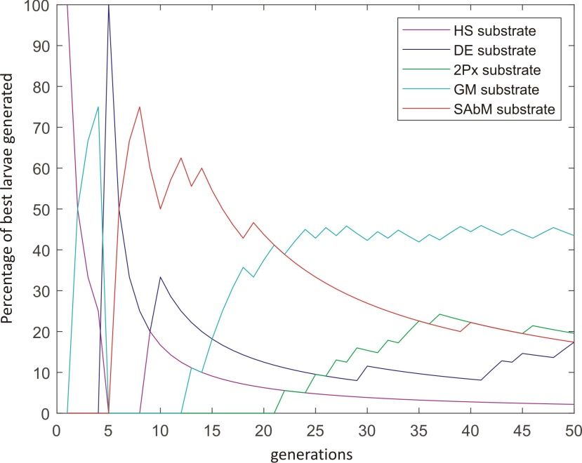
Appl. Sci. 2020, 10, 1168                                                                                    4 of 17

      Table 1. Definition of the variables to optimize in the design of the proposed antenna (see Figure 1
      for details).

                                 Variable                                  Range
                                                     Antenna top view
                                U_T                                            [1,5]
                             U_Patch_h                                        [1,Lp]
                            U_Patch_AY                               [0.5,(Wp-2Circle_R)/2]
                            U_Patch_AX                          [0.5,Lp/2-U_Patch_W-Circle_R]
                               U_Ah                         [1,(Wp-7Mean_A-8Mean_W-2U_T)/2]
                                U_L                                          [0.5,Wp]
                            U_Patch_W                                          [1,5]
                              Circle_R                                      [11,Wp/2]
                            Circle_Angle                                     [0.5,180]
                              Circle_S                                         [3,5]
                             Cirlce_CT                                         [1,5]
                              Circle_T                                         [3,5]
                        Lp=60mm; Wp=90mm
                                                  Antenna ground plane
                                 Mean_W                                   [1,2.7]
                                 Mean_A                                    [1,10]
                                 Mean_h                                   [1,Lp]
                                  U_AV                            [1,(Lp-Mean_h-2U_T)/2]

3. Antenna Optimization: the CRO-SL Algorithm
      A multi-method ensemble CRO-SL is the algorithm used to optimized the proposed antenna.
This algorithm is an advanced version of a basic original version of the CRO [18]. The CRO is an
evolutionary-type algorithm in which the search operators are based on the processes occurring in a
coral reefs, including reproduction, fight for space, or depredation [19]. The pseudocode of the original
CRO is shown below, with the different CRO phases (reef initialization and reef formation), along with
all the operators applied to guide the search.

            Table 2. Description of the pseudo-code for the Coral Reefs Optimization (CRO) algorithm.

                 Algorithm Step                         Pseudo-Code for the CRO Algorithm
                             1              Require: CRO algorithm parameters
                             2              Ensure: An optimal feasible individual (best antenna design)
                             3              Initialize the algorithm and CRO parameters
                             4              for each iteration of the simulation do
                             5                Update values of CRO parameters: predation probability, etc.
                             6                Broadcast spawning and Brooding operators
                             7                Settlement of new corals
                             8                Predation process
                             9                Evaluate the new population in the coral reef
                            10              end for
                            11              Return: the best individual (final solution) from the reef

     The CRO-SL (Coral Reef Optimization with Substrate Layers) is an improved version of the
CRO [19]. It consists of a multi-method ensemble for optimization [27], with extremely good
search capabilities for optimization tasks. The CRO-SL has the same algorithmic structure than
the basic CRO, but several substrate layers are defined in the algorithm, each one implementing a
different search procedure or strategy. In fact, the CRO-SL is an ensemble approach which promotes
competitive co-evolution, where each substrate layer may represent different processes (different
models, search operators, problem’s parameters, etc.), though the multi-method version, in which the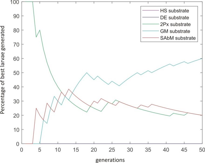
Appl. Sci. 2020, 10, 1168                                                                                  5 of 17

substrate layers represent different search operators, has been the most successful version. Details on
the overall CRO-SL algorithm and the mechanisms to include substrate layers are well-reported in
reference [19]. The main steps of the CRO algorithm have been detailed in Table 2.

3.1. Substrate Layers Implemented
     Though different search strategies can be defined at the practitioner’s discretion, this work adopts
a five-substrate construct of the CRO-SL. They are briefly described below:

1.    HS: Mutation using the Harmony Search procedure. Harmony Search [28] is a well-known
      meta-heuristic based on the how a music orchestra improvises a melody. HS substrate controls
      the generation of new larvae in one of the following ways: (i) with a probability HMCR in (0, 1)
      (Harmony Memory Considering Rate), the value of a component of the new solution is drawn
      uniformly from the same values of the component in other corals of the current reef; and (ii) with
      a probability PAR in (0, 1) (Pitch Adjusting Rate), where small adjustments are applied to the
      values of the current solution.
2.    DE: Differential Evolution algorithm mutation. This substrate is based on the DE algorithm
      defined in reference [29]. This approach introduces a differential mechanism for exploring the
      search space. In this case, new larvae are generated by perturbing the current larva by using a
      vector of differences between two individuals in the population. This perturbation is defined as
      x0 i = x1 i + F(x2 i − x3 i ) (where F stands for a weighting the perturbation amplitude, 0.6 in this case).
      After this perturbation of the current larva, the perturbed vector x0 is in turn combined with an
      alternative (different) coral in the reef, by means of a classical 2-points crossover, as defined next.
3.    2Px: Classical two-points crossover. The crossover operator is the most used operator for
      exploring the search space in evolutionary computation algorithms [30]. It consists of coupling
      two individuals at random, and then, after choosing two points for the crossover, interchanging
      the genetic material in between these two points. In the current CRO-SL implementation, one larva
      to be crossed comes from the 2Px substrate, whereas the other can be chosen from any part of
      the reef.
4.    GM: Gaussian Mutation. We consider a traditional Gaussian mutation of the form x0 i = xi +
      Ni (0, σ2 ), where Ni (0, σ2 ) is a random number following the Gaussian distribution of 0 mean
      and variance σ2 . We introduce a linear decreasing of σ value during the algorithm, from
      0.2(A-B) to 0.02(A-B), where [B,A] is the domain search. Note that this procedure produces a
      stronger mutation in the beginning of the algorithm, and a fine tuning of the search with smaller
      displacements nearing the end or the algorithm’s evolution.
5.    SAbM: Strange Attractors-based Mutation. This is a new search operator proposed in reference [31],
      specifically designed to use fractal geometric patterns in the search of new larvae. Specifically, it
      is designed to generate structures of non-linear dynamical systems with chaotic behavior [32].
      Interested reader may consult reference [31] to obtain more information on this operator.

3.2. Objective Function: Antenna Simulation and Calculation
      The objective function considered (f (x)) to guide the algorithm toward optimal antenna
optimization and takes into account different design requirements of the device, such as its resonant
frequency and bandwidth. Specifically, in order to calculate f (x), we first take into account a
discretization of the S11 antenna parameter, which is calculated by simulation using the CST software,
as described in the next subsection. In this case, a discretization in steps of 2 MHz is considered.
To calculate f (x), several frequency bands for mobile communication systems (including LTE and 5G)
has been considered. For each frequency band, the mathematical formulation of the objective function
is the following:
                                   g f (x) = 0.8·N−10dB + 0.1·M + 0.1·M∗                           (1)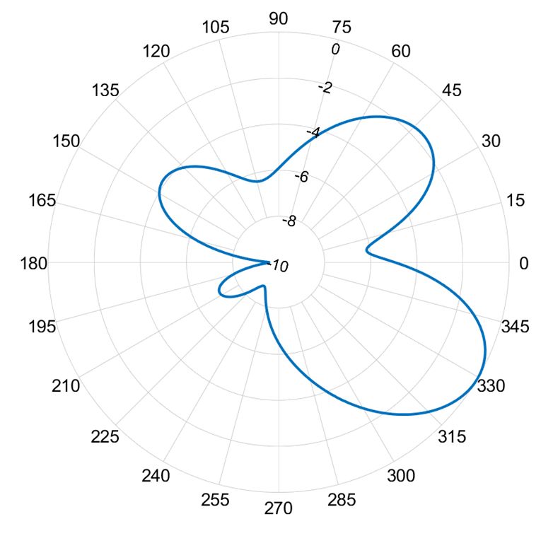
Appl. Sci. 2020, 10, x FOR PEER REVIEW 6 of 17
Appl. Sci. 2020, 10, 1168 6 of 17
( ) = 0.8 ∙ + 0.1 ∙ + 0.1 ∙ ∗ (1)
where N−10dB stands for the number of S11 points in the observation window under −10 dB, M =
where
| meanN(S−10dB stands for the number of S11 points in the observation window under −10 dB,
11 )|, M = |min(S11 )| and f stands for a given selected frequency band. The final objective
∗
function value f (x) is∗ =obtained
M = | mean (S 11 )|, M |min(S11by
)| and f stands
adding for a given
the value of g f (selected
x) for allfrequency band.
the frequency The final
bands objective
f considered:
function value f(x) is obtained by adding the value of ( ) for all the frequency bands f considered:
X
f (x) = g f (x) (2)
( )= ( ) (2)
f
Note that
Note that this
this function
function takes
takes into
into account
account the
the antenna
antenna bandwidth
bandwidth forfor all
all the
the frequency
frequency bands
bands
considered, the
considered, the resonant
resonant frequency,
frequency, andand the
the actual
actual value
value of the antenna
of the antenna reflection
reflection coefficient.
coefficient. In
In order
order
to make the calculation, we define a measurement window at each selected frequency band, with aa
to make the calculation, we define a measurement window at each selected frequency band, with
resolution of
resolution of 20MHz:
20MHz: (1)(1)ff11 = 791−870 MHz
= 791−870 MHz (5G); (2) ff22 ==1.7−2.3
(5G); (2) 1.7−2.3GHz
GHz (LTE); (3) ff33 ==3.3−3.8
(LTE); (3) 3.3−3.8GHz
GHz(5G).
(5G).
Note that
Note that these
thesefrequency
frequencybandsbandscover
coverthe majority
the of of
majority communications
communications services such
services as 2G/3G/4G
such and
as 2G/3G/4G
also LTE and 5G bands of ultimate mobile communication
and also LTE and 5G bands of ultimate mobile communication systems. systems.
Antenna Simulation with CST Software
3.2.1. Antenna Simulation with CST Software
CST Microwave Studio© from Dassault Systèmes SE (France) is a well-known software package
CST Microwave Studio© from Dassault Systèmes SE (France) is a well-known software package
for electromagnetic analysis and simulation in the high frequency range. It is able to provide a
for electromagnetic analysis and simulation in the high frequency range. It is able to provide a fully
fully automatic meshing procedure of any electromagnetic device and its simulation using different
automatic meshing procedure of any electromagnetic device and its simulation using different
possible simulation techniques, depending on the case (transient solver, frequency domain solver,
possible simulation techniques, depending on the case (transient solver, frequency domain solver,
integral equation solver, etc.). The idea is to launch the antenna simulation for each solution encoded
integral equation solver, etc.). The idea is to launch the antenna simulation for each solution encoded
in the CRO-SL algorithm (a given antenna design). The CRO-SL has been coded in Matlab, and we
in the CRO-SL algorithm (a given antenna design). The CRO-SL has been coded in Matlab, and we
are able to call the CST simulation directly from Matlab, so the hybridization of the CRO-SL and the
are able to call the CST simulation directly from Matlab, so the hybridization of the CRO-SL and the
CST software for antenna simulation is direct. Figure 2 shows this hybridization process: the CST
CST software for antenna simulation is direct. Figure 2 shows this hybridization process: the CST
software is launched in order to simulate each larva (antenna design) in the CRO-SL. After the antenna
software is launched in order to simulate each larva (antenna design) in the CRO-SL. After the
simulation, we calculate the value of the objective function associated with the simulated antenna
antenna simulation, we calculate the value of the objective function associated with the simulated
using Equations (1) and (2), and this value is used in the evolution of the CRO-SL algorithm.
antenna using Equations (1) and (2), and this value is used in the evolution of the CRO-SL algorithm.
Figure 2. Hybridization
Hybridization of
of the
the CST
CST simulation
simulation software
software with
with the
the Coral Reefs Optimization
Optimization with
Substrate Layer (CRO-SL) for optimized the parameters of the proposed antenna.
4. Computational
4. Computational Evaluation
Evaluation and
and Results
Results
This section
This section presents
presents the
the computational
computational evaluation
evaluation of
of the
the proposed
proposed antenna,
antenna, by
by means
means of
of several
several
simulations using
simulations usingthe
theCRO-SL
CRO-SLandandCSTCSTsoftware.
software.In Inthethe first
first experiment
experiment carried
carried out,out, we consider
we consider the
the highest two frequency bands (f and f , associated with LTE and 5G mobile communication
highest two frequency bands (f2 and f3, associated with LTE and 5G mobile communication systems).
2 3
In this case, the CRO-SL algorithm is able to obtain a good solution for the problem, within 50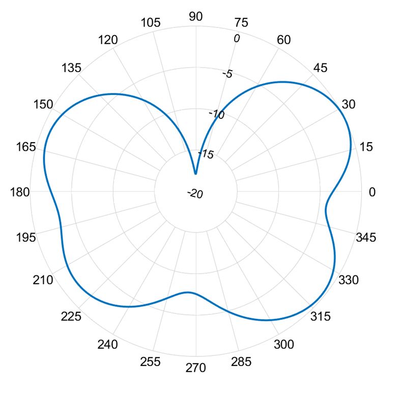
Appl. Sci. 2020, 10, 1168 7 of 17
Appl. Sci. 2020,
systems). In 10, x FOR PEER
this REVIEW algorithm is able to obtain a good solution for the problem, within 7 of 50
17
Appl. Sci. 2020, 10, x case, the CRO-SL
FOR PEER REVIEW 7 of 17
generations, as can be in the S11 antenna parameter obtained (Figure 3), with peaks under −10 dBs
generations,
generations, as
as can be
be in
canbands in the
the SS1111 antenna
antenna parameter obtained (Figure 3),
3), with peaks under
under −10 dBs
dBs in
in both frequency considered. Theparameter
best solution obtained (Figure
(antenna) obtainedwithbypeaks
the CRO-SL −10
is shown in
both
both frequency
frequency bands
bands considered.
considered. The best
TheInbest solution (antenna) obtained by the CRO-SL is shown in
in Figure 4 (front and bottom view). thissolution
case, the(antenna) obtained followed
fitness evolution by the CRO-SL
by the isCRO-SL
shown is in
Figure
Figure 4in4 (front
(front and bottom view). In
In this
this case, the
the fitness evolution followed by
by the
the CRO-SL is shown
shown Figureand bottom
5. The CRO-SLview). performance case,dependsfitness
on evolution followedsubstrates
how the different CRO-SL
operateisforshown
this
in
in Figure
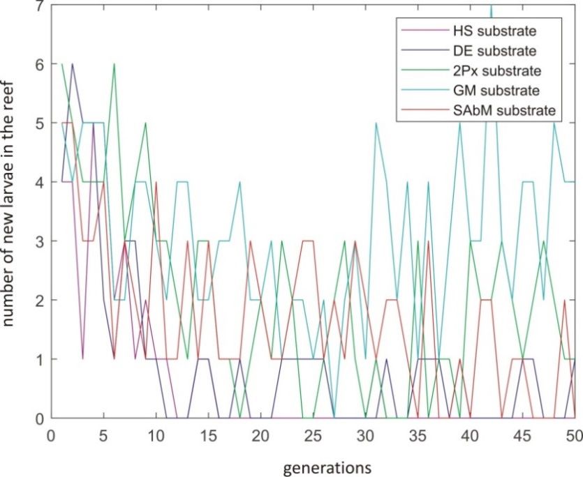
FigureFigure5.
5. The
The6 CRO-SL
CRO-SL performance depends on
on how the different substrates operate for this
problem. shows theperformance
percentage ofdepends best solutions howandthethe different
number ofsubstrates
solutions operate
got into thefor reef
this
problem.
problem. Figure 6 shows
Figuresubstrates.
6 shows the the percentage of best solutions and the number of solutions got
got into the
into
for the different Thispercentage of best solutions
is a good indication of the bestandsubstrates
the number of solutions
for this specific optimization the
reef
reef for
for the
the different
different substrates.
substrates. This
This is
is aa good
good indication
indication of
of the
the best
best substrates
substrates for
for this
this specific
specific
problem. In this case, the GM substrate is the most active substrate in the CRO-SL to obtain good
optimization
optimization problem.
problem. In
In this
this case,
case,bythe GM
thetheGM substrate
substrate is
is the
the most
most active
active substrate
substrate inin the
the CRO-SL
CRO-SL to to
solutions for the problem, followed SAbM and 2Px operators.
obtain good solutions for the problem, followed by the
obtain good solutions for the problem, followed by the SAbM and 2Px operators. SAbM and 2Px operators.
Figure 3.
3. Reflection
Figure3.
Figure Reflection coefficient
Reflectioncoefficient of
coefficientof the
ofthe proposed
theproposed antenna
proposedantenna optimized
antennaoptimized for
forff2f22and
optimizedfor and
andfff333 frequency
frequency bands.
frequency bands.
bands.
(a)
(a) (b)
(b)
Figure
Figure 4.
Figure4.4. Final
Final antenna
Final antenna layout
antenna layout for
layout for the
for the two-frequency
the two-frequency bands
two-frequency bands optimization
bands optimization case,
optimization case, after
case, after the
after the optimization
the optimization
optimization
process.
process. (a)
(a) Front
Front view;
view; (b)
(b) bottom
bottom view.
view.
process. (a) Front view; (b) bottom view.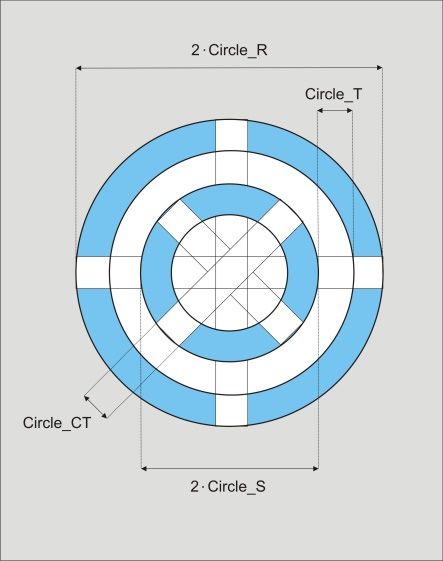
Appl. Sci. 2020, 10, 1168                                                                                8 of 17
Appl. Sci. 2020, 10, x FOR PEER REVIEW                                                                  8 of 17

                   Evolution
     Figure 5.5.Evolution
     Figure                    ofCRO-SL
                          of the  the CRO-SL    fitness (Equation
                                        fitness (Equation           (2))
                                                          (2)) in two    in two bands
                                                                      frequency  frequency bands
                                                                                      antenna     antenna
                                                                                              optimization
     optimization
     process.       process.

     The design of the antenna with the CRO-SL considering the three frequency bands for LTE and 5G
     The design of the antenna with the CRO-SL considering the three frequency bands for LTE and
has been carried out using the solution for the two frequencies shown above as initial point. In order
5G has been carried out using the solution for the two frequencies shown above as initial point. In
to do this, we include the best solution for the two-frequencies case into the initial population of
order to do this, we include the best solution for the two-frequencies case into the initial population
the CRO-SL, completing it with randomly-generated solutions and a number of variations of the
of the CRO-SL, completing it with randomly-generated solutions and a number of variations of the
two-frequencies case obtained by mutation of the best solution. With this, the evolution of the CRO-SL
two-frequencies case obtained by mutation of the best solution. With this, the evolution of the CRO-
towards a high-quality antenna, able to respond in the three frequency bands considered was really fast.
SL towards a high-quality antenna, able to respond in the three frequency bands considered was
Figure 7 shows the S11 antenna parameter obtained by the CRO-SL. Note that the solution obtained is
really fast. Figure 7 shows the S11 antenna parameter obtained by the CRO-SL. Note that the solution
extremely good. In Figure 7a, it is possible to visualize three peaks under −25 dBs in the three frequency
obtained is extremely good. In Figure 7a, it is possible to visualize three peaks under −25 dBs in the
bands, with a peak under −45 dB in the 5G frequency centered in 3.5 GHz, and good bandwidth
three frequency bands, with a peak under −45 dB in the 5G frequency centered in 3.5 GHz, and good
associated with all the frequencies considered. In the same way, the results represented in Figure 7b
bandwidth associated with all the frequencies considered. In the same way, the results represented
confirm the good performance of the optimized antenna. Please note that the markers on Figure 7b
in Figure 7b confirm the good performance of the optimized antenna. Please note that the markers
show the center frequency for each service, but not the exact resonant frequency.
on Figure 7b show the center frequency for each service, but not the exact resonant frequency.
     To further evaluate the performance of the CRO-SL algorithm, the optimization problem with
     To further evaluate the performance of the CRO-SL algorithm, the optimization problem with
three bands has been also tackled with an Evolutionary Algorithm. The initial parameters of the EA are
three bands has been also tackled with an Evolutionary Algorithm. The initial parameters of the EA
the same as the CRO (population size and number of iterations) in order to be fully comparable. Table 3
are the same as the CRO (population size and number of iterations) in order to be fully comparable.
shows the comparison between the CRO-SL algorithms and an Evolutionary algorithm. This table
Table 3 shows the comparison between the CRO-SL algorithms and an Evolutionary algorithm. This
shows the best objective function obtained by each compared algorithm (CRO-5SL optimizing two
table shows the best objective function obtained by each compared algorithm (CRO-5SL optimizing
bands, CRO-5SL optimizing three bands, and EA optimizing three bands). It can be seen that the CRO
two bands, CRO-5SL optimizing three bands, and EA optimizing three bands). It can be seen that the
reach a better solution than the EA even when it is optimizing juts two frequency bands.
CRO reach a better solution than the EA even when it is optimizing juts two frequency bands.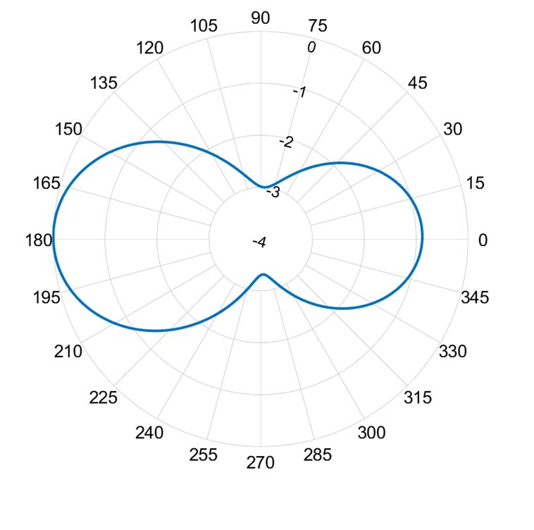
Appl. Sci. 2020, 10, 1168                                                                                        9 of 17
Appl. Sci. 2020, 10, x FOR PEER REVIEW                                                                          9 of 17

                                                       (a)

                                                      (b)
     Figure 6.
     Figure 6. CRO-SL
               CRO-SLsubstrate
                          substrateperformance
                                    performancemetrics
                                                  metrics
                                                        forfor
                                                            thethe  two-frequencies
                                                                two-frequencies       antenna
                                                                                 antenna        optimization.
                                                                                            optimization.      (a)
                                                                                                          (a) Best
     Best substrate
     substrate       for larvae
               for larvae       generation;
                           generation;      (b) substrate
                                       (b) best best substrate for getting
                                                          for getting      larvae
                                                                      larvae       intoreef.
                                                                             into the   the reef.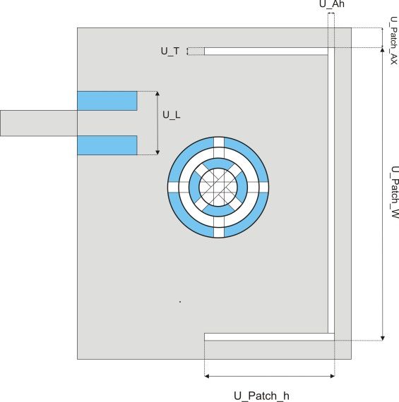
Appl. Sci. 2020, 10, 1168                                                                                           10 of 17
Appl. Sci. 2020, 10, x FOR PEER REVIEW                                                                             10 of 17

                                                        (a)

                                                                                       1.   f1, (55.72-0.92j)
                                                                                       2.   f2, (47.26+2.1j)
                                                                                       3.   f3, (48.38+2.2j)

                                                        (b)
     Figure 7.
     Figure  7. Reflection
                Reflectioncoefficient
                            coefficientof
                                        ofthe
                                           theproposed
                                               proposedantenna
                                                          antennaoptimized
                                                                    optimizedfor f1,ff12, and
                                                                               for            f3 frequency
                                                                                          f2 and            bands.
                                                                                                  f3 frequency     (a)
                                                                                                               bands.
     Reflection  coefficient in dB; (b) reflection coefficient in Smith Chart.
     (a) Reflection coefficient in dB; (b) reflection coefficient in Smith Chart.
Appl. Sci. 2020, 10, 1168 11 of 17
Appl.
Appl. Sci.
Sci. 2020,
2020, 10,
10, xx FOR
FOR PEER
PEER REVIEW
REVIEW 11
11 of
of 17
17
Table
Table Comparison of the
3. Comparison the best results
results obtained by
by the proposed
proposed CRO-SL approaches
approaches and an
an
Table 3.
3. Comparison ofof the best
best results obtained
obtained by the
the proposed CRO-SL
CRO-SL approaches and
and an
evolutionary
evolutionary algorithm.
evolutionary algorithm.
algorithm.
Algorithm
Algorithm Best
Best Fitness
Fitness
Algorithm Best Fitness
CRO-SL
CRO-SL
CRO-SL (two
(two frequency
frequency
(two bands)
bands)
frequency bands) 146.24
146.24
146.24
CRO-SL
CRO-SL (three frequency bands) 155.03
CRO-SL (three
(three frequency
frequency bands)
bands) 155.03
155.03
Evolutionary
Evolutionary Algorithm
Algorithm 130.05
130.05
Evolutionary Algorithm 130.05
Figure
Figure 88 shows
shows the
the final
final antenna
antenna layout
layout obtained
obtained with
with the
the CRO-SL
CRO-SL algorithm
algorithm when
when the
the three
three
frequency bands
bands are
are considered.
considered. As
As can
can be be seen
seen after
after a a comparison
comparison withwith
the the two-frequency
two-frequency
frequency bands are considered. As can be seen after a comparison with the two-frequency bands bands bands
case,
case,
the the obtained
obtained antenna
antenna for thefor the
three three frequency
frequency band band
shows shows
a more a more
reducedreduced
Circle Circle
R R characteristic,
characteristic,
case, the obtained antenna for the three frequency band shows a more reduced Circle R characteristic, with a
with
with aaU_T.
wider wider U_T.
There
wider There
U_T.are alsoare
There also
also differences
differences
are in
in the
the back-side
in the back-side
differences of
of the
the optimized
of the optimized
back-side antennaantenna
optimized (meanders
antenna (meanders
design)
(meanders
design)
when when
comparedcompared
to the to the two-frequencies
two-frequencies case.
design) when compared to the two-frequencies case. case.
(a)
(a) (b)
(b)
Figure
Figure 8.
Figure 8. Final
8. Final antenna
antenna layout
layout for
for the
the three-frequency
three-frequency bands
three-frequency bandsoptimization
bands optimizationcase,
optimization case, after
case, afterthe
after the optimization
the optimization
optimization
process;
process; (a)
process;(a) Front
(a)Front view;
Frontview; (b)
view;(b) Bottom
(b)Bottom view.
Bottomview.
view.
Figure999shows
Figure showsthe
shows thesurface
the surface
surfacecurrent
current
current distribution
distribution
distributionof the
of antenna
of the for 800,
the antenna
antenna for 2400,
for 800, and
2400,3500
800, 2400, andMHz
and 3500bands.
3500 MHz
MHz
As can be
bands.
bands. Asseen,
As can theseen,
can be
be surface
seen, thecurrent
the surfaceiscurrent
surface concentrated
current is around the
is concentrated
concentrated U slotthe
around
around forU
the the
U lower
slot
slot for band.
for the In the
the lower
lower upper
band.
band. In
In
band,
the the
upper higher
band, values
the higher are concentrated
values are around
concentrated the square
around the patch.
square The current
patch.
the upper band, the higher values are concentrated around the square patch. The current distribution The distribution
current in the
distribution
middle
in
in the band isband
the middle
middle mainly
band is locatedlocated
is mainly
mainly in the feeding
located in
in the line andline
the feeding
feeding theand
line annular
and the patch. The
the annular
annular influence
patch.
patch. The of the ground
The influence
influence of
of the
the
plane
ground meanders
plane and
meanders slots is
and also shown
slots is also in the
shown
ground plane meanders and slots is also shown in the figure. figure.
in the figure.
Top
Top view
view Bottom
Bottom view
view
800
800 MHz
MHz
Figure 9. Cont.Appl. Sci. 2020, 10, x FOR PEER REVIEW 12 of 17
Appl. Sci. 2020, 10, 1168 12 of 17
Appl. Sci. 2020, 10, x FOR PEER REVIEW 12 of 17
2200 MHz
2200 MHz
3500 MHz
3500 MHz
Figure 9. Surface current distribution for the antenna obtained in the three-frequency bands
optimization case.
Figure 9.9. Surface
Figure Surface current distribution for the antenna
antenna obtained
obtained in
in the
the three-frequency
three-frequency bands
bands
optimizationcase.
optimization case.
Radiation patterns and gain values for the antenna are given in Figure 10 and Table 4. At 800
MHz, the results are similar to the basic U slot antenna, as the current distribution is mainly located
Radiation
Radiationpatterns
patternsand
andgain
gainvalues forfor
values thethe
antenna are given
antenna in Figure
are given 10 and
in Figure 10Table 4. At 800
and Table MHz,
4. At 800
around it and also, the meanders and slots in the ground plane do not affect specially in this case. For
the results
MHz, the are similar
results are to the basic
similar U slot
to the antenna,
basic as the current
U slot antenna, as thedistribution is mainly located
current distribution is mainlyaround it
located
the rest of the cases, the radiation pattern differs from the basic equivalent antennas, i.e., annular
and also, the meanders and slots in the ground plane do not affect specially in this case. For
around it and also, the meanders and slots in the ground plane do not affect specially in this case. For the rest of
patch or square patch because neither a single element is involved nor the ground plane influence is
the
thecases,
rest ofthethe
radiation pattern
cases, the differspattern
radiation from the basic from
differs equivalent antennas,
the basic i.e., annular
equivalent patch
antennas, orannular
i.e., square
negligible.
patch
patchbecause
or square neither
patchabecause
single element
neither is involved
a single nor the
element ground plane
is involved influence
nor the groundisplane
negligible.
influence is
negligible.
(a)
Figure 10. Cont.
(a)Appl. Sci. 2020, 10, 1168 13 of 17
Appl. Sci. 2020, 10, x FOR PEER REVIEW 13 of 17
(b)
(c)
Figure10.
Figure 10.Final
Finalantenna
antennaradiation
radiationpattern;
pattern;(a)(a)plane
planeEEand
andplane
planeHHat
at800
800MHz;
MHz;(b)
(b)plane
planeEEand
andplane
plane
HHat
at2.2
2.2GHz;
GHz;(c)
(c)plane
planeEEand
andplane
planeHHatat3.5
3.5GHz.
GHz.
Table4.4.Gain
Table Gain(dBi)
(dBi)for
forthe
theantenna
antennaobtained
obtainedin
inthe
thethree-frequency
three-frequencybands
bandsoptimization
optimizationcase.
case.
Frequency (GHz)
Frequency (GHz) Gain (dBi)
Gain (dBi)
0.8 0.8 2.734
2.734
2.2 2.2 4.793
4.793
3.5 8.344
3.5 8.344
The
Theperformance
performance of of
thethe
CRO-SL
CRO-SLalgorithm in thisinproblem
algorithm is shownisinshown
this problem Figure in
11 (fitness
Figure evolution),
11 (fitness
and Figure 12
evolution), performance
and metrics for the
Figure 12 performance different
metrics substrates
for the differentof the CRO-SL.
substrates Again,
of the CRO-SL.the GM is the
Again, the
most
GM isactive operator
the most in operator
active improving inthe searching
improving capabilities
the searching of the algorithm.
capabilities of theThe SAbM and
algorithm. Thethe 2Px
SAbM
are
andalso
the important
2Px are alsoinimportant
the last stages
in theoflast
thestages
algorithm,
of theboth in generating
algorithm, good larvaegood
both in generating and larvae
when the
and
inclusion
when theof the solutions
inclusion of theinto the reef
solutions is considered.
into the reef is considered.Appl. Sci.
Appl. Sci. 2020,
2020, 10,
10, 1168
x FOR PEER REVIEW 14
14 of 17
of 17
Appl. Sci. 2020, 10, x FOR PEER REVIEW 14 of 17
Figure 11. Evolution of the CRO-SL fitness (Equation (2)) in the three-frequency bands antenna
Figure
Figure 11. Evolution of
11. Evolution of the
the CRO-SL
CRO-SL fitness
fitness (Equation
(Equation (2))
(2)) in
in the
the three-frequency
three-frequency bands
bands antenna
antenna
optimization process.
optimization process.
optimization process.
(a)
(a)
Figure 12. Cont.Appl. Sci. 2020, 10, 1168 15 of 17
Appl. Sci. 2020, 10, x FOR PEER REVIEW 15 of 17
(b)
CRO-SLsubstrate-performance
Figure 12. CRO-SL substrate-performancemetrics
metrics
forfor
thethe two-frequencies
two-frequencies antenna
antenna optimization;
optimization; (a)
(a)
BestBest substrate
substrate for for larvae
larvae generation;
generation; (b)(b) Best
Best substrate
substrate forfor getting
getting larvae
larvae into
into thethe reef.
reef.
Here,
Here, we
we have shown how
have shown how we
we are
are able
able to
to optimize
optimize aa multi-band
multi-band microstrip
microstrip textile
textile patch
patch antenna,
antenna,
with capabilities in 5G services, with the CRO-SL algorithm. The obtained device
with capabilities in 5G services, with the CRO-SL algorithm. The obtained device after theafter the optimization
is a robust antenna,
optimization able antenna,
is a robust to operate in the
able three frequency
to operate bands
in the three considered
frequency bands(850 MHz, 2.2(850
considered GHz and
MHz,
3.5 GHz), where communication services such as 5G operate. The results shown for the
2.2 GHz and 3.5 GHz), where communication services such as 5G operate. The results shown for the two-frequencies
and three-frequencies
two-frequencies cases optimizationcases
and three-frequencies shown that we are shown
optimization able to obtain
that wea are
small textile
able antenna
to obtain with
a small
extremely goodwith
textile antenna capabilities in the
extremely desired
good frequency
capabilities bands.
in the desired frequency bands.
5. Conclusions
5. Conclusions
In this paper, we have presented the optimization of a textile multi-band antenna, considering
In this paper, we have presented the optimization of a textile multi-band antenna, considering
LTE and 5G frequency bands. The optimized device is composed by a rectangular microstrip patch
LTE and 5G frequency bands. The optimized device is composed by a rectangular microstrip patch
with two concentric annular slots, a U-Shaped slot, and three sleeved meanders in the ground plane.
with two concentric annular slots, a U-Shaped slot, and three sleeved meanders in the ground plane.
This novel form makes the antenna optimization very hard, since its layout depends on a number of
This novel form makes the antenna optimization very hard, since its layout depends on a number of
design variables, and the antenna must be simulated in order to obtain an optimization result. Thus,
design variables, and the antenna must be simulated in order to obtain an optimization result. Thus,
traditional optimization methods are not applicable, and meta-heuristics algorithms are the best option.
traditional optimization methods are not applicable, and meta-heuristics algorithms are the best
In this case, we propose a novel ensemble-based algorithm—the CRO-SL, a kind of evolutionary
option. In this case, we propose a novel ensemble-based algorithm—the CRO-SL, a kind of
algorithm able to combine different search operators within a single population of possible solutions
evolutionary algorithm able to combine different search operators within a single population of
to the problem. The objective function which guides the evolution of the algorithm is obtained after
possible solutions to the problem. The objective function which guides the evolution of the algorithm
the antenna simulation with a specific simulation software for electromagnetic analysis in the high
is obtained after the antenna simulation with a specific simulation software for electromagnetic
frequency range. In the experimental evaluation of the proposed method, we have shown the design
analysis in the high frequency range. In the experimental evaluation of the proposed method, we
of two different kind of antennas for two and three frequency bands, both including 5G frequencies.
have shown the design of two different kind of antennas for two and three frequency bands, both
In both cases, the CRO-SL algorithm is able to obtain designs with a high performance in the required
including 5G frequencies. In both cases, the CRO-SL algorithm is able to obtain designs with a high
frequency bands, as shown in the S11 antenna parameter obtained. The textile antennas designed have
performance in the required frequency bands, as shown in the S11 antenna parameter obtained. The
a small size (around 60 mm), and the antenna substrate would allow their inclusion in different types
textile antennas designed have a small size (around 60 mm), and the antenna substrate would allow
of fabrics or clothes, providing them with LTE and 5G capacity connection.
their inclusion in different types of fabrics or clothes, providing them with LTE and 5G capacity
connection.
Author Contributions: R.S.-M., D.M.-V., and P.-L.L.-E. performed the simulations, built the platform to connect
the software to do the optimization with the electromagnetic simulation tool. C.C.-G. and S.S.-S. designed and
Author Contributions:
adjusted R.S.-M.,
the optimization D.M.-V.,All
algorithm. and P.-L.L.-E.
the authors performed the simulations,
have contributed built
to writing and thereviewing
platform to
theconnect
paper.
the authors
All softwarehave
to do theand
read optimization withpublished
agreed to the the electromagnetic simulation
version of the tool. C.C.-G. and S.S.-S. designed and
manuscript.
adjusted the optimization algorithm. All the authors have contributed to writing and reviewing the paper.
Funding: This work has been partially supported by the Spanish Ministerial Commission of Science and
Technology (MICYT)
Funding: This workthrough project
has been number
partially TIN2017-85887-C2-2-P.
supported by the Spanish Ministerial Commission of Science and
Technology (MICYT) through project number TIN2017-85887-C2-2-P.Appl. Sci. 2020, 10, 1168 16 of 17
Conflicts of Interest: The authors declare no conflict of interest.
References
1. Panwar, N.; Sharma, S.; Singh, A.K. A survey on 5G: The next generation of mobile communication.
Phys. Commun. 2016, 18, 64–84. [CrossRef]
2. Locher, I.; Klemm, M.; Kirstein, T. Troster. Design and characterization of purely textile patch antennas.
IEEE Trans. Adv. Packag. 2006, 29, 777–788. [CrossRef]
3. Hertleer, C.; Hendrik, R.; Vallozzi, L.; van Langenhove, L. A textile antenna for off-body communication
integrated into protective clothing for firefighters. IEEE Trans. Antennas Propag. 2009, 57, 919–925. [CrossRef]
4. Dierck, A.; Agneessens, S.; Declercq, F.; Spinnewyn, B.; Stockman, G.J.; Van Torre, P.; Vallozzi, L.; Ginste, D.V.;
Vervust, T.; Vanfleteren, J.; et al. Active textile antennas in professional garments for sensing, localization
and communication. Int. J. Microw. Wirel. Technol. 2014, 6, 331–341. [CrossRef]
5. Lemey, S.; Agneessens, S.; van Torre, P.; Baes, K.; Vanfleteren, J.; Rogier, H. Wearable flexible lightweight
modular RFID tag with integrated energy harvester. IEEE Trans. Microw. Theory Tech. 2016, 64, 2304–2314.
[CrossRef]
6. Bayram, Y.; Zhou, Y.; Shim, B.S.; Xu, S.; Zhu, J.; Kotov, N.A.; Volakis, J.L. E-textile conductors and polymer
composites for conformal lightweight antennas. IEEE Trans. Antennas Propag. 2010, 58, 2732–2736. [CrossRef]
7. Tak, J.; Lee, S.; Choi, J. All-textile higher order mode circular patch antenna for on-body to on-body
communications. Microw. Antennas Propag. 2015, 9, 576–584. [CrossRef]
8. Liu, F.-X.; Kaufmann, T.; Xu, Z.; Fumeaux, C. Wearable applications of quarter-wave patch and half-mode
cavity antennas. IEEE Antennas Wirel. Propag. Lett. 2015, 14, 1478–1481. [CrossRef]
9. Lee, H.; Jinpil, T.; Jaehoon, C. Wearable Antenna Integrated into Military Berets for Indoor/Outdoor
Positioning System. IEEE Antennas Wirel. Propag. Lett. 2017, 16, 1919–1922. [CrossRef]
10. Sanchez-Montero, R.; Salcedo-Sanz, S.; Portilla-Figueras, J.A.; Langley, R. Hybrid PIFA-patch antenna
optimized by evolutionary programming. Prog. Electromagn. Res. 2010, 108, 221–234. [CrossRef]
11. Das, A.; Mandal, D.; Ghoshal, S.P.; Kar, R. Concentric circular antenna array synthesis for side lobe suppression
using moth flame optimization. AEU Int. J. Electron. Commun. 2018, 86, 177–184. [CrossRef]
12. Ustun, D.; Akdagli, A. Design of band notched UWB antenna using a hybrid optimization based on ABC
and DE algorithms. AEU Int. J. Electron. Commun. 2018, 87, 10–21. [CrossRef]
13. Sanchez-Montero, R.; Camacho-Gomez, C.; Lopez-Espı, P.L.; Salcedo-Sanz, S. Optimal Design of a Planar
Textile Antenna for Industrial Scientific Medical (ISM) 2.4 GHz Wireless Body Area Networks (WBAN) with
the CRO-SL Algorithm. Sens. J. 2018, 18, 1982. [CrossRef]
14. Awl, H.N.; Abdulkarim, Y.I.; Deng, L.; Bakir, M.; Muhammadsharif, F.F.; Karaaslan, M.; Unal, E.; Luo, H.
Bandwidth Improvement in Bow-Tie Microstrip Antennas: The Effect of Substrate Type and Design
Dimensions. Appl. Sci. 2020, 10, 504. [CrossRef]
15. Prabhaka, H.V.; Kummuri, U.K.; Yadahalli, R.M.; Munnappa, V. Effect of various meandering slots in
rectangular microstrip antenna ground plane for compact broadband operation. Electron. Lett. 2007, 43,
848–850. [CrossRef]
16. Hossa, R.; Byndas, A.; Bialkowski, M.E. Improvement of compact terminal antenna performance by
incorporating open-end slots in ground plane. IEEE Microw. Wirel. Compon. Lett. 2004, 14, 283–285.
[CrossRef]
17. Zhang, Z.Y.; Fu, G.; Zuo, S.L. A miniature sleeve meander antenna for TPMS application. J. Electromagn.
Waves Appl. 2009, 23, 1835–1842. [CrossRef]
18. Salcedo-Sanz, S.; del Ser, J.; Landa-Torres, I.; Gil-Lopez, S.; Portilla-Figueras, J.A. The Coral Reefs Optimization
algorithm: A novel metaheuristic for efficiently solving optimization problems. Sci. World J. 2014, 739768.
[CrossRef]
19. Salcedo-Sanz, S. A review on the coral reefs optimization algorithm: New development lines and current
applications. Prog. Artif. Intell. 2017, 6, 1–15. [CrossRef]
20. Langley, R.; Voudouris, K.; Batchelor, J.C. Annular ring patch antennas. In Proceedings of the IEEE
Colloquium on Multi-Band Antennas, London, UK, 26 October 1992; pp. 6–11.
21. Mahmoud, S.F. A new miniaturized annular ring patch resonator partially loaded by a metamaterial ring
with negative permeability and permittivity. IEEE Antennas Wirel. Propag. Lett. 2004, 3, 19–22. [CrossRef]Appl. Sci. 2020, 10, 1168 17 of 17
22. Bao, X.L.; Ammann, M.J. Compact annular-ring embedded circular patch antenna with cross-slot ground
plane for circular polarization. Electron. Lett. 2006, 42, 192–193. [CrossRef]
23. Bao, X.L.; Ammann, M.J. Dual-frequency circularly-polarized patch antenna with compact size and small
frequency ratio. IEEE Trans. Antennas Propag. 2007, 55, 2104–2107. [CrossRef]
24. Zhang, Y.; Hong, W.; Yu, C.; Kuai, Z.Q.; Don, Y.; Zhou, J.Y. Planar ultrawideband antennas with multiple
notched bands based on etched slots on the patch and/or split ring resonators on the feed line. IEEE Trans.
Antennas Propag. 2008, 56, 3063–3068. [CrossRef]
25. Lee, K.F.; Yang, S.L.S.; Kishk, A.A.; Luk, K.M. The versatile U-slot patch antenna. IEEE Antennas Propag. Mag.
2010, 100, 71–88. [CrossRef]
26. Hsieh, C.; Chiu, T.T.; Lai, C. Compact dual-band slot antenna at the corner of the ground plane. IEEE Trans.
Antennas Propag. 2009, 57, 3423–3426. [CrossRef]
27. Wu, G.; Mallipeddi, R.; Suganthan, P.N. Ensemble strategies for population based optimization
algorithms—A survey. Swarm Evol. Comput. 2019, 44, 695–711. [CrossRef]
28. Geem, Z.W.; Kim, J.H.; Loganathan, G.V. A new heuristic optimization algorithm: Harmony Search.
Simulation 2001, 76, 60–68. [CrossRef]
29. Storn, R.; Price, K. Differential Evolution—A simple and efficient heuristic for global optimization over
continuous spaces. J. Glob. Optim. 1997, 11, 341–359. [CrossRef]
30. Eiben, A.E.; Smith, J.E. Introduction to Evolutionary Computing; Springer: Berlin, Germany, 2003.
31. Salcedo-Sanz, S. Modern meta-heuristics based on nonlinear physics processes: A review of models and
design procedures. Phys. Rep. 2016, 655, 1–70. [CrossRef]
32. Grassberger, P.; Procaccia, I. Characterization of strange attractors. Phys. Rev. Lett. 1983, 50, 346–349.
[CrossRef]
© 2020 by the authors. Licensee MDPI, Basel, Switzerland. This article is an open access
article distributed under the terms and conditions of the Creative Commons Attribution
(CC BY) license (http://creativecommons.org/licenses/by/4.0/).You can also read