FLUSH & FILL CART - MODEL: SFFC-70/2 - OPERATION & MAINTENANCE MANUAL - Stinar
←
→
Page content transcription
If your browser does not render page correctly, please read the page content below
FLUSH & FILL CART
O PE R AT I O N & M A I N T E N A N C E M A N UA L

MODEL: SFFC-70/2

sales@stinar.com | P 651.454.5112 | F 651.454.5143 | www.stinar.com   REV.10.2020
Effective pages   SECTION                   PAGE     DATE
                  Title Page                1        January 2021

                  List of Effective Pages   2        January 2021
                  Contents                  3-4      January 2021
                  Introduction              5-7      January 2021

                  SECTION 1
                  Introduction              8        January 2021

                  Section 1-1               9-15     January 2021

                  Section 1-2               16-25    January 2021

                  Section 1-3               26-27    January 2021

                  SECTION 2
                  Introduction              28       January 2021

                  Section 2-1               29-32    January 2021

                  Section 2-2               33-35    January 2021

                  Section 2-3               36       January 2021

                  SECTION 3
                  Introduction              37       January 2021

                  SECTION 4
                  Introduction              38       January 2021

                  Section 4-1               39       January 2021

                  Section 4-2               40       January 2021

                  Section 4-3               41-52    January 2021

                                                    Flush & Fill Cart SFFC-70/2 | 2
Table of Contents   MANUAL OVERVIEW ������������������������������������������������������������������������������ 7
                    SECTION 1 | GENERAL INFORMATION & OPERATING
                    PROCEDURES ������������������������������������������������������������������������������������������� 8
                      1.1 | Description �������������������������������������������������������������������������������� 11
                          1.1.1 | Equipment Systems and Components ��������������������������������������11
                              1.1.1.1 | Cart Chassis �������������������������������������������������������������������������������������� 11
                              1.1.1.2 Coolant System������������������������������������������������������������������������������������ 11
                    Figure 1.1.1 | Flush & Fill Cart Model SFFC-70/2��������������������������������������������13
                    Figure 1.1.1.2 | Coolant System (Fill Mode)����������������������������������������������������14
                              1.1.1.3 | Electric Motor������������������������������������������������������������������������������������15
                              1.1.1.4 | Electrical System������������������������������������������������������������������������������15
                    Figure 1.1.1.4 | Electrical System ��������������������������������������������������������������������17
                      1.2 | Operation ���������������������������������������������������������������������������������� 18
                          1.2.1 | Operating Controls and Indicators��������������������������������������������18
                              1.2.1.1 | Flush and Fill Cart System Controls and Indicators����������������������18
                          1.2.2 Pre-Operation Checks ��������������������������������������������������������������������18
                          1.2.3 | Operating Procedures������������������������������������������������������������������19
                              1.2.3.1 | Filling the Coolant Tank������������������������������������������������������������������19
                              1.2.3.2 | Draining the contaminated coolant from the aircraft��������������19
                    Figure 1.2.3 | Coolant Tank operation������������������������������������������������������������20
                    Figure 1.2.3.2 | Handle Position����������������������������������������������������������������������21
                              1.2.3.3 | Flushing the system (Figure 1.2.3.3 A) ����������������������������������������� 22
                              1.2.3.4 Filling the Aircraft with Coolant (figure 1.2.3.3)����������������������������� 22
                    Figure 1.2.3.3 A | Flush and Fill Mode������������������������������������������������������������23
                    Figure 1.2.3.3 B | Valve Position����������������������������������������������������������������������24
                    Figure 1.2.3.4 | Valve Position��������������������������������������������������������������������������25
                              1.2.3.5 | Deaerate (figure 1.2.3.5 A)������������������������������������������������������������26
                              1.2.3.6 | Pumping out Waste tank (figure 1.2.3.6)��������������������������������������26
                              1.2.3.7 | Towing the Flush and Fill Cart��������������������������������������������������������26
                    Figure 1.2.3.5 A | Deaerate Mode��������������������������������������������������������������������27
                    Figure 1.2.3.5 B | Valve Position����������������������������������������������������������������������28
                    Figure 1.2.3.6 A | Pumping out of the Waste tank ��������������������������������������29
                    Figure 1.2.3.6 B | Valve Position����������������������������������������������������������������������30
                              1.2.3.7 Storing the Flush and Fill Cart������������������������������������������������������������31
                      1.3 | Specifications and Capabilities �������������������������������������������� 32
                              1.3.1 | General Specifications����������������������������������������������������������������������32
                              1.3.2 | Electric Motor��������������������������������������������������������������������������������������32
                              1.3.3 | Coolant System ����������������������������������������������������������������������������������32
                    SECTION 2 | SERVICING THE FLUSH AND FILL CART���������������������� 34
                      2.1 | Servicing������������������������������������������������������������������������������������� 35
                          2.1.1 | Cart Chassis������������������������������������������������������������������������������������35
                              2.1.1.1 | Brake Adjustment ��������������������������������������������������������������������������� 35
                              2.1.1.1 | Wheels and Tires ����������������������������������������������������������������������������� 35
                              2.1.1.1 | Sheet, Bar and Tubular Member (Non-Load Bearing)��������������� 35

                                                                                                 Flush & Fill Cart SFFC-70/2 | 3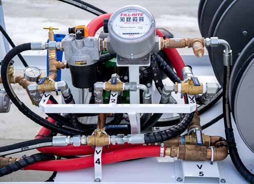
2.1.2 | Coolant System������������������������������������������������������������������������������35
           2.1.2.1 | Coolant Tank����������������������������������������������������������������������������������� 35
           2.1.2.2 | Strainer��������������������������������������������������������������������������������������������� 35
           2.1.2.3 | Filter��������������������������������������������������������������������������������������������������� 35
Figure 2.1.2.1 | Coolant Tank Drain ����������������������������������������������������������������36
           2.1.2.4 | Pump ������������������������������������������������������������������������������������������������37
           2.1.2.5 | Plumbing ������������������������������������������������������������������������������������������37
       2.1.3 | Motor������������������������������������������������������������������������������������������������37
           2.1.3.1 | Belt Drive, motor to pump��������������������������������������������������������������37
           2.1.3.2 | Motor Servicing��������������������������������������������������������������������������������37
       2.1.4 | Electrical System����������������������������������������������������������������������������37
           2.1.4.1 | Electric Cables and Wiring������������������������������������������������������������37
       2.1.5 | Scheduled Service��������������������������������������������������������������������������37
       2.1.6 | Non-scheduled Service ����������������������������������������������������������������38
       2.1.7 | Lubrication��������������������������������������������������������������������������������������38
           2.1.7.1 | Flush and Fill Cart���������������������������������������������������������������������������� 38
  2.2 | Troubleshooting����������������������������������������������������������������������� 39
       2.2.1 | Troubleshooting Table������������������������������������������������������������������39
Figure ### | TITLE����������������������������������������������������������������������������������������������41
  2.3 | Adjustments ����������������������������������������������������������������������������� 42
       2.3.1 | Brake Adjustments������������������������������������������������������������������������42
SECTION 3 | OVERHAUL���������������������������������������������������������������������� 43
SECTION 4 | PARTS LIST ���������������������������������������������������������������������� 44
  4.1 | Manufacturer Identification ���������������������������������������������������� 45
  4.2 | Detailed Parts List������������������������������������������������������������������� 46
       4.2.1 | Understanding the Columns ������������������������������������������������������46
           4.2.1.1 | Figure/Item No.������������������������������������������������������������������������������� 46
           4.2.1.2 | Manufacturer’s Part No. ��������������������������������������������������������������� 46
           4.2.1.3 | Description��������������������������������������������������������������������������������������� 46
           4.2.1.4 | Vendor Code ��������������������������������������������������������������������������������� 46
           4.2.1.5 | QTY��������������������������������������������������������������������������������������������������� 46
       4.2.2 | Instructions for Ordering Parts and Assemblies��������������������46
PARTS ORDER FORM ���������������������������������������������������������������������������� 47
Figure 4.3.1 | Flush and Fill Cart Model SFFC-70/2 ��������������������������������������48
Figure 4.3.1 | Flush and Fill Cart Model SFFC-70/2 - Table��������������������������49
Figure 4.3.3 | Wheel Hub Assembly����������������������������������������������������������������50
Figure 4.3.3 | Wheel Hub Assembly - Table ��������������������������������������������������51
Figure 4.3.4 | Coolant System��������������������������������������������������������������������������52
Figure 4.3.4 | Coolant System - Table ������������������������������������������������������������53
Figure 4.3.8 | Electrical System ����������������������������������������������������������������������55
Figure 4.3.8 | Electrical - Table������������������������������������������������������������������������56

                                                                                  Flush & Fill Cart SFFC-70/2 | 4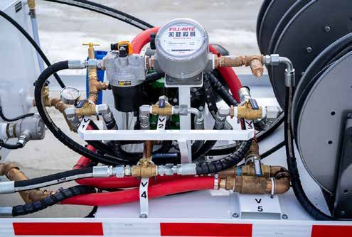
MANUAL OVERVIEW
                  This publication provides operating and maintenance instructions,
                  including detailed parts lists for the Flush and Fill Cart model number
                  SFFC-70/2. This cart was manufactured by:
                  Stinar, LLC
                  10061 State Hwy. 30
                  Blooming Prairie, MN 55917

                  Section 1 | General Information & Operating
                  Instructions
                  Includes a unit description, recommended procedures for operation, plus
                  specifications and capabilities.

                  Section 2 | Servicing The Flush & Fill Cart
                  Provides unit maintenance information, service and lubrication data and
                  a troubleshooting guide.

                  Section 3 | Maintenance
                  Presents instructions for component overhaul and repair.

                  Section 4 | Parts List
                  Contains a manufacturers list and illustrated parts lists for the
                  assemblies, sub-assemblies and systems within the unit.

                                                                   Flush & Fill Cart SFFC-70/2 | 5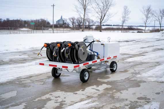
SECTION 1 | GENERAL INFORMATION & OPERATING PROCEDURES
                  SAFETY ALERT SYMBOL – Look for this symbol to point out important
                  safety precautions.

                  DANGER: The word “DANGER” denotes a most serious specific potential
DANGER!           hazard. A forbidden practice should definitely be avoided in connection
Example           with a serious hazard.

                  WARNING: The word “WARNING” is used to denote a specific potential or
WARNING!          hidden hazard which, if not avoided, has the potential for serious injury.
Example

                  CAUTION: The word “CAUTION” is used to denote a general reminder of
CAUTION!          good safety practices or to direct attention to unsafe practices. Following
Example           safe behavioral practices consistent with operating and maintenance
                  instructions will help the operator and others avoid accident involvement.

                  NOTE: The word “NOTE” is used to denote something that can cause minor
NOTE:             machine damage or poor performance if ignored.
Example

                  IMPORTANT: The word “IMPORTANT” informs the reader of something
                  they need to know to prevent minor machine damage if a certain
                  procedure is not followed.

                  General Safety
                   •   Do not rush
                   •   Do not alter your machine
                   •   Read and follow all warning labels. Replace any labels that are
                       missing or illegible
                   •   Check all controls and operating functions of the machine in a safe
                       area before starting work
                   •   Never allow unauthorized persons around machinery when
                       performing operation functions
                   •   A Fire Extinguisher and First Aid kit should be carried in the truck at
                       all times
                   •   Comply with airline and Facility Regulations when approaching
                       aircraft and parking

                                                                   Flush & Fill Cart SFFC-70/2 | 6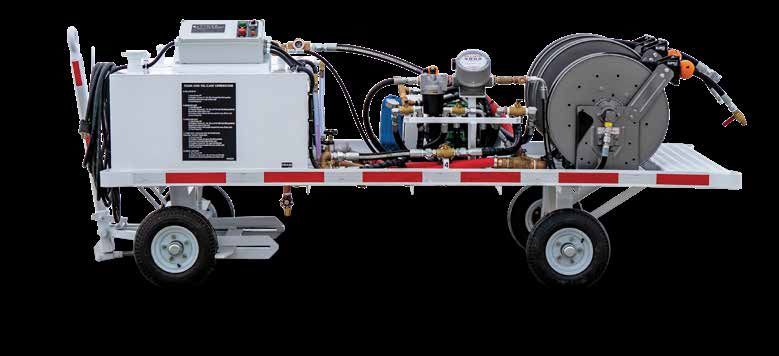
SECTION 1 | GENERAL INFORMATION & OPERATING PROCEDURES

                  Before Operation
                   1.   Perform a general all-around visual inspection and equipment check
                        of the entire unit
                   2. Perform any checks required by Airport or Airline Regulations.
                   3. Check all markings and nameplates for legibility
                   Always determine hydraulic oil level and fill tank to proper level with all
                   hydraulic cylinders fully-retracted. Overfilling may occur if cylinders are
                   not retracted which may damage the system

                  During Operation
                   The procedures outlined in this Manual are suggested general operating
                   procedures. For specific aircraft servicing, follow procedures specified by
                   your airline.

                  After Operation
                   Always unhitch unit on level ground. Block wheels and set brakes
                   before unhitching.

                  Service Safety
                   •    Do not clean, adjust or service this unit while it is in motion
                   •    Periodically check tightness of nuts and bolts and check for loose,
                        worn or misaligned parts. Use only approved replacement parts.
                   •    Any new components installed during repair must include the
                        current safety signs specified by Stinar Corp.
                   •    Disconnect power to electrical components before servicing or
                        replacing them
                   •    Perform all work in accordance with authorized standard shop
                        practices
                   •    To avoid possible injury, be sure tire is deflated before removing tire
                        from rim
                   •    Perform no welding, cutting, patching and such on any load bearing
                        or supporting structure. If such repairs are necessary, contact the
                        Engineering Department of Stinar Corporation before making any
                        alterations.
                   •    Should there be a hydraulic system associated with this unit, always
                        determine hydraulic oil level and fill tank to the proper level with all
                        hydraulic-actuating cylinders fully-retracted. Otherwise, damage may
                        occur to the tank when the system is operated.
                   •    Do not mix hydraulic oils of different specifications. Oils may not
                        be compatible, which may cause damage to the hydraulic system
                        components.

                                                                     Flush & Fill Cart SFFC-70/2 | 7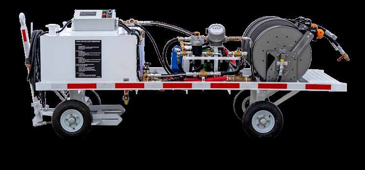
SECTION 1 | GENERAL INFORMATION & OPERATING PROCEDURES
                  Your safety and the safety of those around you depend upon the operator
                  using care and good judgment in the operation of this unit. Know the
                  positions and functions of all controls before attempting to operate.
                  All equipment has limitations. Understand the speed, braking, steering,
                  stability and load characteristics of the unit before starting operation.
                  READ YOUR OPERATOR’S MANUAL!

                                                                   Flush & Fill Cart SFFC-70/2 | 8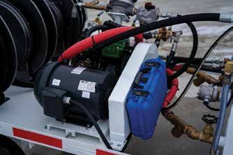
SECTION 1 | GENERAL INFORMATION & OPERATING PROCEDURES

1.1 | DESCRIPTION   The Stinar Flush and Fill Cart, Model SFFC-70/2 is a towable service unit
                    designed for draining contaminated air vehicle coolant for storage in the
                    cart and eventual disposal. Heated, filtered and deaerated clean coolant is
                    then pumped from the service cart into the air vehicle in three modes. There
                    is a flush mode that eliminates residual contaminated coolant. There is a
                    fill mode that supplies the aircraft with fresh coolant. The deaerate feature
                    removes all the gases in the system from the coolant. The flush and fill
                    cart consists of a coolant tank, waste tank and coolant-dispensing system
                    mounted on a two-axle trailer. The coolant dispensing system consists of a
                    electric motor-driven diaphragm pump that supplies coolant through a fill
                    hose. A bleed hose is also used on the cart.

                    1.1.1 | Equipment Systems and
                    Components
                    The major operating systems and components of the flush and fill cart are
                    described in the paragraphs below. See Figure 1.1.1 for locations.

                    1.1.1.1 | Cart Chassis
                    The flush and fill cart chassis provides a mobile platform for the coolant
                    tank, coolant-dispensing system and electrical system components. The
                    chassis consists of a rectangular steel frame with a fixed rear axle and a
                    pivoting front axle assembly. The front axle assembly includes a tow bar
                    and front wheel brakes engaged by raising and locking the tow bar in an
                    upright position. The cart is equipped with four 4:80 x 4:00 x 8 tires.

                    1.1.1.2 | Coolant System
                    The coolant-dispensing system is used to pump contaminated coolant
                    from the aircraft. See Figure 1.1.1.2 for coolant system schematic. The fol-
                    lowing paragraphs describe the major system components:
                    Coolant Tank
                    The coolant tank is bolted to the cart frame. The tank is constructed from
                    type 304 stainless steel. Internal safety baffles prevent sloshing and dis-
                    tribute load forces. The coolant tank has the following features:

                    COMPONENT                   DESCRIPTION
                                                The tank vent is located on top of the tank.
                    Vent                        This vent pipe is covered with a mushroom-
                                                type breather/vent cap.
                                                Valve beneath the cart allows the tank to be
                    Drain Valve
                                                drained.
                                                Fill connection for the coolant tank is 2 inches
                    Fill Connection             in diameter and provided on the top of the
                                                fresh coolant tank.

                                                                      Flush & Fill Cart SFFC-70/2 | 9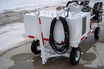
SECTION 1 | GENERAL INFORMATION & OPERATING PROCEDURES

                   COMPONENT      DESCRIPTION
                                  The gauges are located on the left side of the
                                  fresh tank and the right side of the waste tank.
                   Level Gauges
                                  They indicate the level of liquid in each of the
                                  tanks.

                                                       Flush & Fill Cart SFFC-70/2 | 10
FIGURE 1.1.1 | FLUSH & FILL CART MODEL SFFC-70/2
Pump
Waste Tank
Motor
Clean Tank
Control Box Filter
Coolant Fill Port
Main Valve Bank Return Hose
Supply Hose
Tow Bar
Ground Cable
Bleed Hose
Flush & Fill Cart SFFC-70/2 | 11FIGURE 1.1.1.2 | COOLANT SYSTEM (FILL MODE)
Flush & Fill Cart SFFC-70/2 | 12SECTION 1 | GENERAL INFORMATION & OPERATING PROCEDURES
The following coolant system components are located on the Flush and
Fill Cart.
COMPONENT DESCRIPTION
This gate valve is located at the tank outlet
into the pump suction line. When closed, this
Tank Shutoff Valves
valve allows service to be performed on the
system without draining the tank. (V6 & V7)
This gate valve is located underneath the tank
Tank Drain Valves
to allow coolant to be drained from the tank.
The filter between the supply hose and the
pump filters impurities from the coolant
Filter
leaving the pump. This filter is a 5-micron
absolute filter and has a removable element.
The strainer prevents particles from entering
Y Strainer the pump. The strainer is located just after
the tank shutoff valve.
The pump delivers coolant from the coolant
tank to the aircraft. This diaphragm pump is
Pump
belt-driven by the motor and runs whenever
the motor is running.
The meter measures, in gallons, the amount
of coolant pumped to the aircraft. The meter
Meter is directly above the main valves. It may
be reset to zero using a knob on the meter
housing.
The sight glass allows the operator to visually
Sight Glass see that coolant is moving through the service
hoses and into the waste tank.
Two check valves are installed in the system.
They are located before valve 4 to ensure
Check Valves that coolant does not flow back through the
strainers and into the tanks. Refer to the
coolant schematic (Fig. 1.1.1.2)
1.1.1.3 | Electric Motor
The motor is mounted parallel to the pump in the center of the cart. The
drive shaft of the motor drives through a belt to the diaphragm pump. Op-
erating controls for the motor are located on the control panel.
1.1.1.4 | Electrical System
The electrical system for the cart is a 480 volt three phase AC system.
Electrical Components
The primary electrical components are described below:
Flush & Fill Cart SFFC-70/2 | 13SECTION 1 | GENERAL INFORMATION & OPERATING PROCEDURES
COMPONENT DESCRIPTION
10 Horsepower AC Electric Motor
Electric Motor
1760 RPM - 3Phase
Heater-440V-3Ph-60Hertz-12000W
Heater W/60/250DegF Intregal Adjustable
Thermostat
Flush & Fill Cart SFFC-70/2 | 14FIGURE 1.1.1.4 | ELECTRICAL SYSTEM
THERMOSTAT
Flush & Fill Cart SFFC-70/2 | 15SECTION 1 | GENERAL INFORMATION & OPERATING PROCEDURES
1.2 | OPERATION Prior to operating the Stinar Flush and Fill Cart SFFC-70/2, all operators
and maintenance personnel should become thoroughly familiar with
the instructions given in this Manual. No instructions are given for
positioning the cart, as airline policy should be followed.
1.2.1 | Operating Controls and Indicators
1.2.1.1 | Flush and Fill Cart System Controls and
NOTE:
The pump operates whenever
Indicators
the motor is running.
COMPONENT DESCRIPTION
See motor controls, pre-starting checks and
Electric Motor
operating instructions for the motor.
This push button ON/START switch for the
START Button
motor is located on the control box.
This push button OFF/STOP switch for the
STOP Button
motor is located on the control box.
This ON/OFF switch for the heater is located
Heater Control
on the control box.
A ball valve is installed on the aircraft end of
the supply hose. Closing this valve prevents
Shutoff Valve, Hose
water in the hose from spilling after the hose
is disconnected from the aircraft.
The meter is located directly above the main
Meter valves. It measures, in gallons, the amount of
coolant dispensed to the aircraft.
This float gauge on the left side of the fresh tank
Tank Level Gauge and the right side of the waste tank indicates the
amount of coolant present in the tank.
This gate valve is located at the bottom of
the tank in the pump suction line on both
Tank Shutoff Valve fresh and waste tanks. It must be open when
pumping coolant and should be closed only
during maintenance.
1.2.2 Pre-Operation Checks
The following checks should be performed at the beginning of each day
or shift:
1. Make sure brakes operate properly.
2. Check hoses for cracks and wear.
3. Check the tank level gauge to make sure there is ample coolant in
the tank. Make sure the tank vent is not plugged before filling tank.
4 . Check condition of the tires and wheels.
Flush & Fill Cart SFFC-70/2 | 16FIGURE 1.2.3 | COOLANT TANK OPERATION
Pump
Waste Tank
Motor
Clean Tank
Heater
Pump ON/OFF
Coolant Fill Port ON/OFF Filter
Electric Cable
Main Valve Bank Return Hose
Supply Hose
Tow Bar
Ground Cable
Bleed Hose
Flush & Fill Cart SFFC-70/2 | 17SECTION 1 | GENERAL INFORMATION & OPERATING PROCEDURES
WARNING! 1.2.3 | Operating Procedures
ALWAYS HAVE THE PUMP
SHUT OFF WHEN CHANGING 1.2.3.1 | Filling the Coolant Tank
PROCEDURES AND VALVE The fill coupling for the fresh coolant tank is located on top of the tank. To
POSITIONS. fill tank:
1. Flip up hatch on two-inch fill port.
2. Also fill coolant until the tank is full.
1.2.3.2 | Draining the contaminated coolant from the
NOTE:
Comply with Airline Operating
aircraft
and Service Manuals for ap- 1. Position the flush and fill cart near the aircraft’s service panel.
proaching aircraft and parking. 2. Set tow vehicle brakes. If cart is disconnected from tow vehicle, set cart
brakes by manually raising and latching tow bar in upright position.
3. See figure 1.2.3 for the location of the return hose.
CAUTION!
Do not kink, bend sharply, mash
or otherwise deform the supply
and return hoses.
4. Ensure that V1, V2, V3, V4 and V5 are positioned so that the handle is
pointed towards the side of the cart (handles can only be positioned
towards the side or the rear).
5. Open the aircraft service panel. Connect the quick-release coupling
on the water fill hose to the aircraft inlet.
6. Drain the liquid from the air vehicle per applicable aircraft
technical order.
7. Tow the servicing unit to an approved waste disposal facility and
drain the contaminated coolant through the drain valve. (V-9)
Flush & Fill Cart SFFC-70/2 | 18FIGURE 1.2.3.3 | FLUSH AND FILL MODE
Flush & Fill Cart SFFC-70/2 | 19SECTION 1 | GENERAL INFORMATION & OPERATING PROCEDURES
1.2.3.3 | Flushing the System (Figure 1.2.3.3)
WARNING!
ENSURE NO POWER IS APPLIED 1. Position the flush and fill cart near the aircraft’s service panel and set
TO THE POWER CABLE WHEN the carts brakes.
DISCONNECTING FROM THE 2. See figure 1.2.3 for the location of hoses, grounding cable and
SERVICE CART. power cable.
3. Connect the power cable to 480-volts, 3-phase, 60 Hz power source.
4. Connect the supply hose, return hose and bleed hose to the air vehicle.
5. Position valves V1, V2, V3 and V5 with the handles pointed towards
the side of the cart.
6. Set the heater switch to ON.
7. Allow the coolant temperature in the supply tank to stabilize at
90 degrees Fahrenheit. (Refer to the supply temperature gauge,
figure 1.2.3)
8. Push the Pump ON button.
9. Flush the cooling system per applicable aircraft technical order.
10. When flushing is complete, push the Pump OFF button.
11. Set the Heater switch to OFF.
12. Disconnect the supply hose, the return hose and the bleed hose from
the aircraft.
WARNING!
ENSURE NO POWER IS APPLIED 1.2.3.4 Filling the Aircraft with Coolant (figure 1.2.3.3)
TO THE POWER CABLE WHEN 1. Position the flush and fill cart near the aircraft’s service panel and set
CONNECTING TO THE SERVICE the carts brakes.
CART. 2. See figure 1.2.3 for the location of hoses, grounding cable and
power cable.
Flush & Fill Cart SFFC-70/2 | 20FIGURE 1.2.3.5 | DEAERATE MODE
Flush & Fill Cart SFFC-70/2 | 21SECTION 1 | GENERAL INFORMATION & OPERATING PROCEDURES
3. Connect the power cable to 480-volts, 3-phase, 60 Hz power source.
CAUTION! 4. Connect the supply hose, return hose and bleed hose to the air vehicle.
Do not kink, bend sharply, mash 5. Set the Heater switch to ON.
or otherwise deform the supply
and return hoses. 6. Allow the coolant temperature in the supply tank to stabilize at 90
degrees Fahrenheit. (refer to the supply temperature gauge, figure 1.2.3)
7. Set valves V1, V2, V3, V4 and V5 so that the handles point toward the
side of the cart.
8. Push the Pump On button to start.
9. Fill the liquid-cooling system per applicable aircraft technical order.
10. When fill operation is complete, push the Pump OFF button.
11. Set the Heater switch to OFF.
12. Disconnect the supply hose, the return hose and the bleed hose from
the aircraft.
13. Tow the flush and fill cart to an approved waste disposal facility to
drain the contaminated reservoir through drain valve v-9 located at
the bottom of the waste tank.
1.2.3.5 | Deaerate (figure 1.2.3.5)
1. Position the flush and fill cart near the aircraft’s service panel and set
the carts brakes.
2. See figure 1.2.3 for the location of hoses, grounding cable and
power cable.
3. Connect the power cable to 480-volts, 3-phase, 60 Hz power source.
4. Connect the supply hose, return hose and bleed hose to the air vehicle.
Flush & Fill Cart SFFC-70/2 | 22FIGURE 1.2.3.6 | PUMPING OUT OF THE WASTE TANK
Flush & Fill Cart SFFC-70/2 | 23SECTION 1 | GENERAL INFORMATION & OPERATING PROCEDURES
5. Set the Heater switch to ON.
WARNING! 6. Allow the coolant temperature in the supply tank to stabilize at 90
ENSURE THAT NO POWER IS
degrees Fahrenheit. (refer to the supply temperature gauge, figure
APPLIED TO THE POWER CABLE
WHEN CONNECTING TO THE
SERVICE CART.
CAUTION!
Do not kink, bend sharply, mash
or otherwise deform the supply
and return hoses.
1.2.3)
7. Position valves V1, V2, V3 and V5 so that the handles are pointed
towards the side of the cart.
8. Position valve V4 so that the handle is pointed toward the rear of the cart.
WARNING! 9. Push the Pump button to ON.
ENSURE THAT NO POWER IS
APPLIED TO THE POWER CABLE 10. Deaerate the liquid cooling in conjunction with the fill procedures in
WHEN CONNECTING TO THE applicable aircraft technical order.
SERVICE CART. 11. When deaerate operation is complete, push the Pump OFF
12. Set the Heater switch to OFF
13. Disconnect the supply hose, the return hose and the bleed hose from
the aircraft.
WARNING!
ENSURE NO POWER IS APPLIED 1.2.3.6 | Pumping out Waste Tank (figure 1.2.3.6)
TO THE POWER CABLE WHEN 1. Position the flush and fill cart near a waste disposal facility and set
DISCONNECTING FROM THE the carts brakes.
SERVICE CART.
2. See figure 1.2.3 for the location of hoses, grounding cable and
power cable.
3. Connect the power cable to 480-volts, 3-phase, 60 Hz power source.
CAUTION!
Do not kink, bend sharply, mash
or otherwise deform the supply
and return hoses.
Flush & Fill Cart SFFC-70/2 | 24SECTION 1 | GENERAL INFORMATION & OPERATING PROCEDURES
4. Set valves V1, V3 and V5 so that the handles point toward the rear of
the cart.
5. Set valves V2, V4 so that the handle points toward the side of the
cart.
6. Push the Pump On button to start.
7. When drain operation is complete, push the pump OFF button.
1.2.3.7 | Towing the Flush and Fill Cart
The flush and fill cart is intended for use on paved airport service roads
and service areas. Do not tow or park the cart on soft or unstable ground
where it might get bogged down or topple over.
1. Connect tow bar to tow vehicle
2. Tow unit to vicinity of aircraft. Do not exceed a towing speed of 10
MPH (16 km/hr), especially when cornering with carts in tow.
1.2.3.8 Storing the Flush and Fill Cart
If the cart will be stored in an unheated area, prepare the cart for storage
as follows:
1. Drain all coolant from tank and hoses.
Flush & Fill Cart SFFC-70/2 | 25SECTION 1 | GENERAL INFORMATION & OPERATING PROCEDURES
1.3 | SPECIFICATIONS 1.3.1 | General Specifications
AND CAPABILITIES OVERALL DIMENSIONS
Overall Length
Tow bar Up 114 in. (2896 mm)
Tow bar Down 116 in. (3987 mm)
Overall Width 48 in. (1219 mm)
Overall Height 47 in. (1194 mm)
Rear Bumper Height 22.5 in (572 mm)
Ground Clearance 4 in (102 mm)
Wheelbase 73 in. (1854 mm)
Wheel Track 42 in. (1067 mm)
Tires (4) 4:80 x 4:00 x 8 pneumatic, 4 ply
Brakes Front wheel, tow bar operated
1.3.2 | Electric Motor
Manufacturer Stinar
Model 426003
Type 220/460 AC
Service Factor 1.15
Efficiency 89.5%
Frame 215T
Horsepower, Maximum 10 Hp @ 1800 RPM
1.3.3 | Coolant System
COOLANT TANK
Material Type 304 stainless steel
Capacity 70 U.S. gal (266 liter)
Vent 3/4 in (19 mm)
Fill Connection 2 in (25.4 mm)
PUMP (DRIVEN BY ELECTRIC MOTOR)
Manufacturer UDOR U.S.A., Inc.
Model RO-106
Type Diaphragm
Maximum Pressure 300 PSI
Maximum Flow 26 GPM
Maximum RPM 540 RPM
Flush & Fill Cart SFFC-70/2 | 26SECTION 1 | GENERAL INFORMATION & OPERATING PROCEDURES
CLEAN AND CONTAMINATED COOLANT HOSE
Length 50 ft (15.24 m)
Inside Diameter ¾ in (19 mm)
BLEED HOSE
Length 75 ft (22.8 m)
Inside Diameter 3/8” (9.525 mm)
Flush & Fill Cart SFFC-70/2 | 27SECTION 2 | SERVICING THE FLUSH AND FILL CART
This section contains servicing and lubrication information for the Stinar
NOTE: Flush and Fill Cart, Model SFFC-70/2. The instructions in this section are
Perform all work in recommended by the manufacturer and are intended to assist service
accordance with authorized
personnel in developing their own service schedules based on their
standard shop practices.
specific environment.
No special tools are required, other than those found in a modern
automotive garage or airline service facility for ground support equipment.
Flush & Fill Cart SFFC-70/2 | 28SECTION 2 | SERVICING THE FLUSH AND FILL CART
2.1 | SERVICING 2.1.1 | Cart Chassis
2.1.1.1 | Brake Adjustment
Check operation of brake mechanism before each use. Adjust brake
linkage if needed. See Adjustment section of this chapter for procedure.
WARNING!
Perform no welding, cutting, 2.1.1.2 | Wheels and Tires
patching and such on any load
• Check tires for condition before each use.
bearing or supporting structure.
If such repairs are necessary, • Repair tires as required.
contact the Engineering de- • Check operation of brake mechanism before each use. Adjust brake
partment of Stinar Corporation linkage if required.
before making any alterations.
2.1.1.3 | Sheet, Bar and Tubular Member (Non-Load
Bearing)
• Repair cracks or metal fatigue failures by stop-drilling, welding,
patching or splicing.
• Prime and paint marred, rusted or damaged finish using a high
CAUTION! grade primer and finish paint materials.
Do not attempt any welding • Clean areas that are extremely oily or greasy with mineral solvents
on tank unless top access and degreasers before painting.
cover is removed.
2.1.2 | Coolant System
2.1.2.1 | Coolant Tank
• The coolant tank may be drained by opening the valve at the
bottom of the tank (V8 fig. 2.1.2). To drain contaminated reservoir,
open valve at the bottom of contaminated reservoir (V8). Drain
contaminated coolant only at an approved waste disposal facility.
• The tank is constructed of type 304 stainless steel. If welding is
necessary, use only type 308 rod or wire.
• The coolant tank interior and coolant system may be cleaned with a
mild detergent. Flush thoroughly after repairs and cleaning.
2.1.2.2 | Strainer
A strainer is located in the line running from the coolant tank to the
pump on both tanks. A gate valve adjacent to the strainer allows service
to be performed on the strainer without draining the coolant tank. Clean
strainer screen every 100 hours.
2.1.2.3 | Filter
A filter is located between the flow meter and the supply hose. Replace the
filter element according to the filter condition indicator. When the green
indicator turns red, it is time to replace the filter element.
Flush & Fill Cart SFFC-70/2 | 29FIGURE 2.1.2.1 | COOLANT TANK DRAIN
V8
Flush & Fill Cart SFFC-70/2 | 30SECTION 2 | SERVICING THE FLUSH AND FILL CART
2.1.2.4 | Pump
The pump requires no lubrication or regular servicing. Check coupling to
motor periodically or if a vibration is noticed.
2.1.2.5 | Plumbing
Check tank, hose, valves and fittings for leaks and proper function daily.
Tighten any loose connections. Replace hoses if cracked, cut or worn.
2.1.3 | Motor
2.1.3.1 | Belt Drive, Motor to Pump
Check the belt drive to the pump every 100 hours.
2.1.3.2 | Motor Servicing
See motor manual for full maintenance schedule, procedures and
illustrations. Following is a very basic servicing guide.
2.1.4 | Electrical System
2.1.4.1 | Electric Cables and Wiring
Ensure that all cables and wiring are securely attached. Inspect wiring for
damage on a regular basis. Check for damaged insulation and connectors
and check for loose connections at terminals.
2.1.5 | Scheduled Service
Scheduled service consists of preventive maintenance procedures,
which will assure long and dependable operation of the unit if they are
performed on a regular schedule.
Perform scheduled service in accordance with the guidelines below:
SERVICE INTERVAL METHOD
PROCEDURE
Service motor Various See engine manual.
Check wiring for
50 hours Visual inspection.
corrosion
Check motor to pump
100 hours Visual inspection.
belt drive
Check coolant system
hoses, components
and fittings for
50 hours Visual inspection.
looseness or leaks.
Tighten or replace as
needed
Flush & Fill Cart SFFC-70/2 | 31SECTION 2 | SERVICING THE FLUSH AND FILL CART
SERVICE INTERVAL METHOD
PROCEDURE
Close the tank shut-off
Remove and clean
100 hours valve and unscrew the
strainer
strainer element.
See lubrication
Lubrication paragraph (at end of See lubrication paragraph.
this section)
Unscrew the filter
When Green
Replace filter element when pump is
indicator turns red
off.
2.1.6 | Non-scheduled Service
Non-scheduled service consists of adjustments and maintenance
operations, which are not required at regular intervals, but are performed
as required.
The table below lists common non-scheduled service needs.
SERVICE PROCEDURE PERFORM WHEN
Tighten or replace leaking fittings. Leaks are evident.
Replace cracked, cut or Inspection reveals hoses are
deteriorated hoses. deteriorated or leaks are evident.
2.1.7 | Lubrication
2.1.7.1 | Flush and Fill Cart
Grease fittings on the Flush and Fill Cart should be lubricated monthly
using an automotive-grade lithium grease. See the following table for
locations of fittings:
SERVICE PROCEDURE INTERVAL METHOD
Axle Swivel Shaft (1 fitting) Monthly Lithium grease
Wheel bearings (4) Yearly Lithium grease
Tow bar Monthly Light oil
Brake Bar Pivots Monthly Light oil
Tow Bar Latch Monthly Light oil
Flush & Fill Cart SFFC-70/2 | 32SECTION 2 | SERVICING THE FLUSH AND FILL CART
2.2 | This section includes troubleshooting information for the Stinar installed
systems of the SFFC-70/2. For troubleshooting motor problems, refer to
TROUBLESHOOTING the motor manual
The troubleshooting information that follows provides trouble analysis
for possible malfunctions. Included are possible problems, probable
causes and suggested remedies for problems that may occur. Refer to the
coolant system schematic (Figure 2.2) for assistance with troubleshooting
this system.
The troubleshooting data provided for the electrical system presupposes
that common circuitry checks will be made and that no open leads or
loose connections exist.
2.2.1 | Troubleshooting Table
TROUBLE PROBABLE CAUSE REMEDY
Cart Chassis
Tow bar locked in raised Release foot latch and
position. lower tow bar.
Cart will not turn Adjust brake tension.
left or right. Brakes set too tight. See ADJUSTMENT
section following.
Damaged tire(s). Repair tire(s).
Brakes set too loose. Adjust brake tension.
Unattached brake rod, Reattach rod, bolt or
bolt or nut. nut.
Broken rod, bolt or nut. Replace rod, bolt or nut.
Brakes will not lock.
Broken or missing Repair or replace brake
brake bar. bar.
Broken or missing tow
Replace foot latch.
bar foot latch.
Cart Chassis (continued)
Clean and repack
Seized or broken wheel
Wheel will not turn. bearing or replace
bearing.
bearing.
Coolant System (See Figure 2.2 for Schematic)
Flush & Fill Cart SFFC-70/2 | 33SECTION 2 | SERVICING THE FLUSH AND FILL CART
TROUBLE PROBABLE CAUSE REMEDY
Tank shutoff valve
Open shutoff valve.
closed.
In-line filter clogged. Remove and clean filter.
Check hoses and
No coolant flow. connections for leaks.
Leaks in system.
Repair or replace, as
required.
Insufficient coolant in
Fill tank.
tank.
See pump
Pump problem. troubleshooting in
Appendix B.
Motor malfunctioning. See motor adjustments.
Motor to pump drive
Replace belt
belt damaged.
Low or irregular Water tank breather
Clean breather.
flow. vent clogged.
Ice in tank-to-pump line. Thaw out line.
Check hoses and
Kinked or leaking hose
connections. Repair or
or loose connection.
replace as needed.
Check valve clogged or Clean, repair or replace
broken. valve.
Electrical System
Repair or replace
Start switch problem.
switch.
Motor cannot be
Troubleshoot and
started
Motor problem. repair. See Motor
manual.
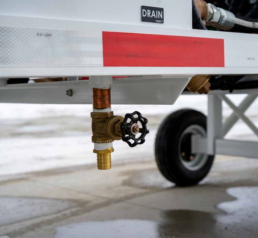
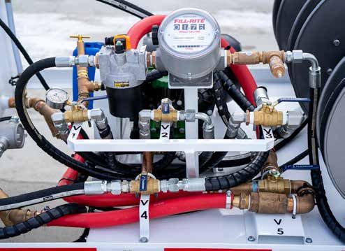
Flush & Fill Cart SFFC-70/2 | 34FIGURE 2.2 | COOLANT SYSTEM
(Flush and Fill Mode)
For Deaerate Mode and Waste Tank Pump Mode refer to Figures 1.2.3.5 and 1.2.3.6
Flush & Fill Cart SFFC-70/2 | 35SECTION 2 | SERVICING THE FLUSH AND FILL CART
2.3 | ADJUSTMENTS 2.3.1 | Brake Adjustments
When the tow bar is raised, a brake bar is pulled against the two front
wheels, braking the cart. To adjust brakes, proceed as follows:
1. Unlatch and lower tow bar. Be sure cart is on a level surface or the
wheels are blocked.
2. Loosen the lock nuts securing the brake rod to the yokes.
3. Turn the brake rod to move the brake bar closer or farther from the
tires as needed.
4. Raise the tow bar. The brake bar should slide forward firmly against
the tires.
5. If necessary, repeat above procedure until the brake is properly
adjusted.
6. Tighten the lock nuts on the brake rod against the yokes.
Flush & Fill Cart SFFC-70/2 | 36SECTION 3 | OVERHAUL
Compliance with recommended maintenance schedules will help
eliminate the need for overhauling the Flush and Fill Cart on the basis of
hours of operation or years of service. Repairs should be limited to the
repair of components that develop defects or show signs of wear.
Flush & Fill Cart SFFC-70/2 | 37SECTION 4 | PARTS LIST
This chapter contains a Manufacturer Identification List and detailed
parts lists. Use this information for requisitioning, storing, issuing
and identification of parts and components of the Flush and Fill Cart,
manufactured by Stinar Corporation.
The manufacturer identification list identifies the vendor sources by
name, address and supply code.
The detailed parts lists include Stinar manufactured assemblies, sub-
assemblies and detail parts, plus detailed breakdowns for selected
vendor manufactured parts.
Flush & Fill Cart SFFC-70/2 | 38SECTION 4 | PARTS LIST
4.1 | MANUFACTURER FED SUPPLY CODE MANUFACTURER
IDENTIFICATION Stinar, LLC
V32526 10061 State Hwy. 30
Blooming Prairie, MN 55917
Flush & Fill Cart SFFC-70/2 | 39SECTION 4 | PARTS LIST
4.2 | DETAILED 4.2.1 | Understanding the Columns
PARTS LIST 4.2.1.1 | Figure/Item No.
This column lists the figure on which the item is shown and the item
number assigned to the part.
4.2.1.2 | Manufacturer’s Part No.
This column lists the part number assigned by the manufacturer and
is required to procure the part. The abbreviation COMM (Commercial)
indicates that several manufacturers produce the part and that it is usually
available from local sources. EX: standard pipe fittings.
4.2.1.3 | Description
This column presents the complete item name required for identification
and procurement and may include the vendor’s name.
4.2.1.4 | Vendor Code
This column shows the vendor code. This code is a U.S. Dept. of Defense
CAGE code preceded by the letter V.
4.2.1.5 | QTY
This column indicates the quantity used per assembly.
4.2.2 | Instructions for Ordering Parts
and Assemblies
Direct all inquiries to:
Stinar, LLC
10061 State Hwy. 30, P.O. Box 127, Blooming Prairie, MN 55917
651-454-5112 | sales@stinar.com | www.stinar.com
Flush & Fill Cart SFFC-70/2 | 40PARTS ORDER FORM
Stinar, LLC
10061 State Hwy. 30, P.O. Box 127, Blooming Prairie, MN 55917
651-454-5112 | sales@stinar.com | www.stinar.com
Print or copy this page and send via email, fax or mail to Stinar, LLC. Please make sure to complete all fields.
Note: Part Numbers and Product Illustrations are included in this Manual
STINAR SERIAL NUMBER
TRUCK CHASSIS OR OTHER
COMPONENT SERIAL NUMBER
PART OR COMPONENT
DESCRIPTION
QUANTITY
SHIPPING METHOD
NAME
COMPANY NAME
SHIP TO ADDRESS
PHONE #
FAX #
Flush & Fill Cart SFFC-70/2 | 41FIGURE 4.3.1 | FLUSH AND FILL CART MODEL SFFC-70/2
13
10
15-20
8
9
7
22
14
12
3
25
11 6
5
4
2
23
21
1
Flush & Fill Cart SFFC-70/2 | 42FIGURE 4.3.1 | FLUSH AND FILL CART MODEL SFFC-70/2 - TABLE
VENDOR
FIG ITEM # MFG PART # DESCRIPTION QTY
CODE
4.3.1-0 SFFC-70/2 Flush and Fill Cart, per Dwg No 049001 Rev D V32526 1
-1 049002 Rev D Cart Frame Weldment V32526 1
-2 030613 Rev G Front Axle Assembly. See Figure 4.3.2. V32526 1
-3 030617 Rev G Tow bar V32526 1
-4 603044 Wheel Hub. See Figure 4.3.3 V32526 4
-5 613007 Tire and Rim V32526 4
-6 030615 Rev H Rear Axle Assembly, Welded to cart frame. V32526 1
-7 049003 Rev D Tank, 70 gal. V32526 1
-8 049004 Rev C Waste Tank, 70 gal V32526 1
-9 426003 Electric Motor. V32526 1
-10 316130 Diaphragm Pump. V32526 1
-11 049000 Rev G Coolant System. See Figure 4.3.4. V32526 1
-12 049006 Rev C Electrical System. See Figure 4.3.8 V32526 1
-13 314000 Vent Mushroom ¾” V32526 2
-14 509024 2” Fill with hasp V32526 1
-15 049005 Rev B Belt Guard V32526 1
-16 705001 Pulley 1 3/8” bore V32526 1
-17 705002 Pulley Bushing V32526 1
-18 705003 Pulley 1” bore V32526 1
-19 705004 Pulley Bushing V32526 1
-20 702079 V-Belt 3VX500 V32526 1
-21 307052 Static Discharge Reel V32526 1
-22 308016 Flow Meter, Gals. V32526 1
-23 307057 Supply Reel V32526 2
-24 307004 Return Reel V32526 1
-25 307056 Bleed Reel V32526 1
Flush & Fill Cart SFFC-70/2 | 43FIGURE 4.3.2 | FRONT AXLE ASSEMBLY
Flush & Fill Cart SFFC-70/2 | 44FIGURE 4.3.2 | FRONT AXLE ASSEMBLY - TABLE
VENDOR
FIG ITEM # MFG PART # DESCRIPTION QTY
CODE
4.3.2-0 040147 Front Axle Assembly, 48 in V32526 1
-1 030617 Towbar Assembly V32526 1
-2 607006 Towbar Latch V32526 1
-3 940018 Flex-top locknut, ½"-13 V32526 1
-4 941013 SAE Flat Washer, ½" V32526 1
-5 938084 Hex-head Cap Screw, ½"-13, 1 ½" V32526 1
-6 508169 Bearing Disc V32526 1
-7 508168 Front Axle Swivel Shaft Housing V32526 1
-8 508170 Front Axle Swivel Shaft V32526 1
-9 030613 Front Axle Assembly, 48 in V32526 1
-10 706043 Yoke, ¾"-10 V32526 2
-11 940030 Flex-top Locknut, ¾"-10 V32526 2
-12 030378 Brake Rod, ¾"-10 x 22" V32526 2
-13 906002 Collar Shaft w/ Set Screw 1" V32526 2
-14 045008 Front Swivel Pin V32526 2
Flush & Fill Cart SFFC-70/2 | 45FIGURE 4.3.3 | WHEEL HUB ASSEMBLY
A
A
3
SECTION A-A
1
5
2
4
Flush & Fill Cart SFFC-70/2 | 46FIGURE 4.3.3 | WHEEL HUB ASSEMBLY - TABLE
VENDOR
FIG ITEM # MFG PART # DESCRIPTION QTY
CODE
4.3.3-0 603044 Wheel Hub V32526 4
-1 603045 Seal, 1 ½” V32526 2
-2 603047 Race V32526 2
-3 603048 Bearing V32526 2
-4 1449 Grease Fitting V32526 1
-5 18907 Hub V32526 1
-6 5999 Flange, welded to Hub, Item 5 V32526 1
-7 14034 Flange, welded to Hub, Item 5 V32526 1
-8 603049 Bolt V32526 5
-9 603053 Nut, not shown V32526 5
Flush & Fill Cart SFFC-70/2 | 47FIGURE 4.3.4 | COOLANT SYSTEM
Flush & Fill Cart SFFC-70/2 | 48FIGURE 4.3.4 | COOLANT SYSTEM - TABLE 1
VENDOR
FIG ITEM # MFG PART # DESCRIPTION QTY
CODE
4.3.4-0 049000 Rev G Coolant system- (flush and fill mode) V32526 1
-1 316130 Pump V32526 1
-2 302063 ¾” 3-way Ball Valve V32526 2
-3 302118 1 ¼” 3-way Ball Valve V32526 1
-4 205006 Pressure Gauge V32526 1
-5 308016 Flow Rate Meter V32526 1
-6 206072 5 micron Absolute Filter V32526 1
-7 302066 Pressure Relief valve V32526 1
-8 302018 Rev A 1” Gate Valve V32526 2
-9 049004 Rev C 70 Gal Waste Tank V32526 1
-10 049003 Rev D 70 Gal Coolant Tank V32526 1
-11 403152 Immersion Heater V32526 1
-12 302021 1 ¼” Gate Valve V32526 2
-13 304013 Y Strainer V32526 2
-14 315000 ¾” Visiflow V32526 1
-15 302108 Check Valve V32526 2
-16 302167 Check Valve V32526 1
-17 302057 Hose Reel ¾” X 50’ V32526 2
-18 305056 Hose Reel ⅜” X 75’ V32526 1
-19 512006 Schrader Air Valve V32526 1
-20 315001 1” Visiflow V32526 2
-21 307004 Hose Reel 1” X 50’ V32526 1
-22 107033 Hose HYD. 1525 PSI 100R1 ¾” x 50’ V32526 50’
-23 107031 Hose HYD. 6GIT ⅜” X 75’ V32526 75’
-24 107034 Hose HYD. 16G1 1” X 50’ V32526 50’
-25 108033 Stem ⅜” 6-6F JK V32526 2
-26 108069 Hydraulic Fitting 12G-12MXP V32526 2
-27 108073 FTTG HYD 16G-16MP V32526 2
-28 310014 Hose Stop ¾” V32526 1
-29 310015 Hose Stop 1” V32526 1
-30 310011 Hose Stop ⅜” V32526 1
-31 302064 1” 3-way ball valve V32526 1
Flush & Fill Cart SFFC-70/2 | 49FIGURE 4.3.4 | COOLANT SYSTEM - TABLE 2
VENDOR
FIG ITEM # MFG PART # DESCRIPTION QTY
CODE
Coolant system
4.3.5-0 V32526 1
Brass
-1 101033 Str- 45 Elbow ¾” V32526 1
-2 101032 Str-90 Elbow ¾” V32526 3
-3 101031 90 Elbow ¾” V32526 3
-4 101026 Nipple ¾” x 2” V32526 2
-5 101020 Nipple Brass comb ½” V32526 4
-6 101025 Nipple Brass Close ¾” V32526 6
-7 101038 Brass Tee ¾” V32526 2
-8 101009 Brass Tee ¾ x ¼” V32526 1
-9 101030 Brass Nipple ¾” x 6 V32526 2
-10 101060 Brass Nipple Comb 1” V32526 2
-11 101053 Brass Nipple 1 x 3” V32526 1
-12 101054 Brass Nipple 1 x 4” V32526 1
-13 101051 Brass Nipple Close 1” V32526 2
-14 101063 Brass Tee 1” V32526 1
-15 101076 Brass Nipple Close 1 ¼” V32526 7
-16 101128 Brass Nipple Comb 1 ¼” V32526 5
-17 101197 Str 45 Elbow 1 ¼” V32526 4
-18 101081 Str 90 Elbow 1 ¼” V32526 3
-19 101110 Hx Brass Bushing V32526 3
-20 101115 Hx Brass Bushing ½ x ⅜” V32526 1
-21 101095 Hx Brass Bushing ½ x 1” V32526 2
-22 101138 Hx Brass Bushing 1 ¼ x ¾” V32526 1
-23 101102 Nipple close 2” V32526 1
24 102071 Hydr Fitting 16MB-12FB V32526 2
Flush & Fill Cart SFFC-70/2 | 50FIGURE 4.3.8 | ELECTRICAL SYSTEM
Flush & Fill Cart SFFC-70/2 | 51FIGURE 4.3.8 | ELECTRICAL - TABLE
VENDOR
FIG ITEM # MFG PART # DESCRIPTION QTY
CODE
4.3.8-0 049006 Rev C Electrical System V32526 1
-1 426003 10 HP Motor V32526 1
-2
-3 402002 Cable 14-4 10 ft V32526 2
-4 402074 Cable 10-4 50 ft V32526 1
-5 400330 3 Pole AC Contactor V32526 2
-6 404171 Nema-4 Enclosure V32526 1
-7 404172 Enclosure Mount Kit V32526 1
-8 410043 Din Mount V32526 1
-9 400326 Switch, Rd Push button V32526 1
-10 400327 Rd Boot V32526 1
-11 400325 Switch, Gn Push button V32526 1
-12 400328 Gn Boot V32526 1
-13 403152 Immersion Heater V32526 1
-14 419004 Transformer 50kva Solacontrol V32526 1
-15 415021 ¾” Cord grip – Plus Seal 415005 V32526 7
-16 415003 ¾” Cord Grip -Nut V32526 7
-17 400329 Overload Relay V32526 1
-18 400332 Selector Switch V32526 1
-19 414091 Plug V32526 1
Inline Fuse (not shown), Transformer-mounted
-20 421056 V32526 1
250V, 5 Amp
Flush & Fill Cart SFFC-70/2 | 52You can also read