Installation & Operation Instructions For Big Dipper W-750-IS and W-1250-IS Internal Strainer (IS) Series Units (Includes 230 VAC Units)
←
→
Page content transcription
If your browser does not render page correctly, please read the page content below
Installation & Operation Instructions
     For Big Dipper W-750-IS and W-1250-IS
        Internal Strainer (IS) Series Units
             (Includes 230 VAC Units)

                            A Big Dipper W-750-IS in a
                               Basement Location

       Copyright ©2011 Big Dipper® Thermaco, Inc. • P.O.Box 2548 • Asheboro, NC 27204
                Toll Free: (800) 633-4204 • V: (336) 629-4651 • F: (336) 626-5739
                  E-mail: info@thermaco.com • Online: www.big-dipper.com
VL                                                                                      Part# MNL-ISCU14000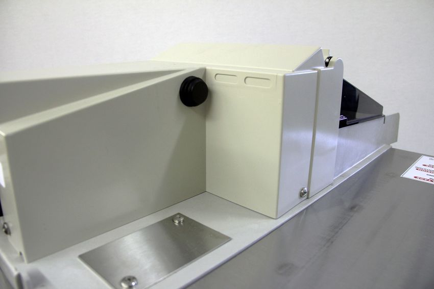
®

                                                               Table of Contents

                      Table of Contents

                 IS System Overview						                                                       3

                 IS System Maintenance					                                                     5

                 IS Timer Operation						                                                       6

                 IS System Troubleshooting				                                                  7

                 How To Reverse IS System Operation			                                          8

                 Plumbing Installation						                                                    9

                 Electrical Installation						                                                  11

                 IS Module Wiring Diagram					                                                  12

                 Junction Box Wiring Diagram				                                                13

                 IS Component Identification				                                                14

                 IS Replacement Parts						                                                     17

                 Limited Warranty						                                                         18

 ©2011 Thermaco, Inc. All rights reserved • Patented/Patents Pending • Specifications subject to change without notice
Thermaco, Inc. • 646 Greensboro St. • Asheboro, N. C. 27204-2548 • Phone (336) 629-4651                MNL-ISCU14000 2
®
Big Dipper® Internal Strainer
(IS) System Overview
Big Dipper® Internal Strainer (IS) System Overview
The Thermaco, Inc. Big Dipper® Automatic Grease and Oils Removal System removes free-
floating grease & oils from kitchen drain water flows. As most food service facility managers
already know, grease buildup within a building’s plumbing drainage system is a major cause of
problems due to drain line blockages. These problems jeopardize normal operations as well as
create health and safety hazards within the facility itself.
The proper installation of a Big Dipper System can reduce or eliminate grease problems. Use
of the Big Dipper assures minimization and/or elimination of costly sewer surcharges and fines
through efficient separation and removal of free-floating grease & oils. In addition, the Big Dipper
also helps reduce or eliminate pumping and disposal costs associated with conventional grease
traps or interceptors. The recovered grease & oils are substantially water-free and are suitable
for recycling by local rendering and/or biodiesel companies.
The Big Dipper system is an automatic, self-cleaning device. As greasy kitchen effluent drains
from kitchen fixtures, the unit traps the grease & oils. These separate from the effluent and rise
to the surface of the separator tank. The unit automatically skims the trapped grease & oils and
transfers the grease & oils to a collection container. A timer controls the self cleaning operation,
activating the skimming wheel at a user-set time. Only the “cleaned” water exits the unit and
flows into the facility drain lines.
The Big Dipper system’s compact footprint allows installation directly at the source where grease
problems originate. The system design also allows easy maintenance and operation requiring only
a minimal amount of daily and weekly maintenance to maintain peak operating performance.
The Big Dipper system design allows for maximum installation flexibility. Reversing the system
operation is a simple as rotating the cover assembly of the unit.
Grease interceptors, grease traps, automatic recovery units, grease removal devices and other
similar plumbing devices receiving kitchen flows from sinks, floor drains, woks and other food
bearing sources may generate odors. There are many factors influencing odor evolution and
dissemination. These include room ventilation, kitchen menu, ambient temperatures, ware wash-
ing practices, grease/oil input, daily input fluid
volume, sanitizers, installation plumbing design
and product maintenance/upkeep. Odors are
usually prevented by good area ventilation,
frequent fluid inputs, good product maintenance
practices and proper product installation. Ad-
ditional steps, including aeration, chlorination,
improved area ventilation and additional mainte-
nance control, may be needed at some sites.
©2011 Thermaco, Inc. All rights reserved • Patented/Patents Pending • Specifications subject to change without notice
Thermaco, Inc. • 646 Greensboro St. • Asheboro, N. C. 27204-2548 • Phone (336) 629-4651 MNL-ISCU14000 3®
Big Dipper® Internal Strainer (IS)
System Overview
Big Dipper® Internal Strainer (IS) Features
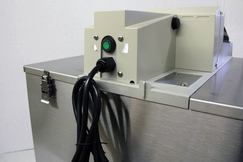
Jog Switch
The Stainless IS Series Big Dipper has a built in Jog
Switch on the side of the housing which allows for quick
and easy monitoring of the unit to ensure that it is op-
erating correctly. By simply pressing the button, the
motor should activate and the skimming wheel should
turn normally. Letting go of the button will disengage
the motor. Using this jog switch will not interfere with
the timer setting of the unit.
Feedback Provided by Jog Switch
• If the unit is not operating regularly, but will work when the button is pressed, it is likely that the
timer on the unit is no longer operating and should be replaced.
• If pressing the button does nothing then there may be a problem with the motor assembly.
Please contact Thermaco or your local service agent.
Energy Saver Switch
Each Stainless IS Series Big Dipper ships with the
heating element activated such that the heater oper-
ates only when the motor is running. Alternatively, the
unit can be run in Energy Saver Mode which deacti-
vates the heater in the unit. The switch for changing
this mode is in the rear of the Center Lid Assembly
just above the power cord. To engage Energy Saver
Mode and deactivate the heater, press and release
the button once. The button will stick out further
than it does when the heater is on. For continuous
operation of the heater, please see the underside of
the center module lid or contact Thermaco or contact
your local service agent.
Energy Saver Switch Settings
Heater On Heater Off
Energy Saver Mode Off Energy Saver Mode On
©2011 Thermaco, Inc. All rights reserved • Patented/Patents Pending • Specifications subject to change without notice
Thermaco, Inc. • 646 Greensboro St. • Asheboro, N. C. 27204-2548 • Phone (336) 629-4651 MNL-ISCU14000 4®
Big Dipper® Internal Strainer (IS)
System Maintenance
Big Dipper® Internal Strainer (IS) System Maintenance
*CAUTION! DISCONNECT POWER TO UNIT BEFORE CLEANING
to prevent damage to the unit and personal injury
*NOTE: Before energizing unit after cleaning, fill tank with water
to protect wipers and heater from damage
Daily Maintenance:
(A) Empty the clear plastic grease/oils collection container (located beside the unit) prior to its
becoming full once each day. The Big Dipper recovers grease and oil virtually water-free so that
they can be recycled. The collector container should be washed periodically so as to maintain
the easy viewing translucent characteristic of the collector.
(B) The internal strainer basket should be removed and emptied into a garbage container by
shaking briskly. Wash the inside and outside surfaces of the strainer after emptying.
Weekly Maintenance:
(A) Check the collection trough and the wiper blades for any solids build-up. Wipe off any accu-
mulated deposits and assure that the wiper blades are clipped in place properly.
(B) Check the Timer to be sure it is set and operating correctly.
(C) Press the Jog Switch button (on the side of the center module) momentarily to ensure that
the motor and skimming wheel are still operating correctly.
(D) Check the thickness of the grease layer at the top of the unit. There should be no appreciable
amount of grease or oil left in the tank immediately after the daily automatic skimming cycle. If
there is more than a 1/2” (13 mm) thick layer of grease after the skimming cycle, this indicates
a need to increase the skimming time. Increase the timer settings accordingly until a clean unit
appearance is obtained after the automatic skimming cycle (A simple guide is to increase the
“on” time by 30 minutes for each 1” (25 mm) of grease layer observed after the skimming cycle).
Quarterly Maintenance:
(A) The internal strainer basket in the unit is designed to remove incidental solids from kitchen
drain flows. Over a period of time, sediment consisting of very fine particles may begin to ac-
cumulate on the bottom of the unit. If this build-up is allowed to continue, it may eventually block
the outlet baffle. To prevent this from occurring, remove the lid and stir the bottom of the unit with
a long handled spatula while water is flowing to flush out the sediment. Occasionally drain and
clean the unit thoroughly. Properly used, a wet-vac may be appropriate for this purpose.
©2011 Thermaco, Inc. All rights reserved • Patented/Patents Pending • Specifications subject to change without notice
Thermaco, Inc. • 646 Greensboro St. • Asheboro, N. C. 27204-2548 • Phone (336) 629-4651 MNL-ISCU14000 5®
Big Dipper® IS System
Suggested Settings/Timer Operation
Big Dipper® IS System Suggested Settings/Timer Operation
Tabs NOT
TO SET TIMER: punched Time-of-day
in indicate indicator point
1. Push on/off tabs on the outer ring “OFF”setting
of timer inward into dial at desired 4 3 2
“ON” times. 1 Tab = 15 minutes. 5 1
Minimum of one (1) tab (15 min- AM 12 12
utes) not to exceed 2 hours in a 7 11
complete run cycle.
8 10
2. Turn dial CLOCKWISE
one or more complete revolutions 9 9 3 9
until the present time is aligned
with the time-of-day indicator 10 8
point. 7
11 7
Dial rotates
3. Fill the unit with water by turning Clockwise 12 6 PM
on the sink water taps, then plug 1 5
the Big Dipper unit into grounded 2 3 4
electrical outlet.
4. Tabs pushed IN = ON Tabs punched in
indicate “ON”setting
Tabs pushed OUT = OFF
NOTE: IN CASE OF POWER FAILURE, RESET TIMER. (See Step 2 above).
After the plumbing installation is complete, the Big Dipper unit needs to be set for the proper au-
tomatic self-cleaning operation for the facility. The Big Dipper W-750-IS model is equipped with
one (1) 24 Hour/96 Event time controller while the W-1250-IS model is equipped with two (2) time
controllers. The time controller is located under the lid of the motor housing mounted on top of
the Big Dipper lid (See Pages labeled “Electrical Connection Detail” sketches of this location).
Depending upon the amount of accumulated grease and oils, the system may need to be reset
to operate more or less time to skim all separated grease and oils. This can be determined by
removing the top cover and observing the depth of the separated grease layer shortly after a
cleaning cycle is completed. This layer should not be more than 1/2” (12 mm) thick. If this layer
is consistently thicker, increase the operating times of the Big Dipper IS System by 30 minutes for
each additional 1” (25 mm) of grease, not to exceed 2 hours in a complete run cycle. If required,
additional run cycles can be added throughout the day. Consequently, if there is any quantity of
water in the grease collector, then the Big Dipper is operating too long. Decrease the amount of
operating time by one tab (15 min.) at a time until no water is collected in the container.
©2011 Thermaco, Inc. All rights reserved • Patented/Patents Pending • Specifications subject to change without notice
Thermaco, Inc. • 646 Greensboro St. • Asheboro, N. C. 27204-2548 • Phone (336) 629-4651 MNL-ISCU14000 6®
Big Dipper® IS System Series
Troubleshooting
Big Dipper unit overflows
(1) Check to see that the outlet pipe is not reduced to a (3) Press the Jog Switch button on the side of the center
smaller size, the outlet piping is vented, has as few 90 module to ensure that the skimming wheel turns.
degree outlet turns as possible, and that no “P” trap is CAUTION: Keep your hands away from moving parts
installed on the outlet. Re-plumb the piping, if neces- to avoid possible injury. If the skimmer motor does not
sary. Check outlet piping for clogs. Have a plumber come on, the motor assembly must be replaced.
clean the line, if necessary.
(4) Check for congealed grease in the unit. If the Big
2) Make sure that the solids strainer is in place and Dipper’s heating element is not warming the unit, the
emptied daily. heating element must be replaced.
3) Check the bottom of the grease chamber for exces- (5) Some sites do not generate enough grease to be
sive solids and silt buildup which may be blocking the captured by the skimming process. Set Timer for mini-
outlet baffle. Disconnect the power and use a long mum operation - 1 Tab (15 Min.)
handled spatula or similar instrument to stir the bottom
while water flows through the unit. If necessary, drain Objectionable odor
and clean the sediment from the unit. To prevent recur- (1) Make sure grease/oil is being skimmed properly
rence, schedule this cleaning to be done on a regular from the unit.
basis (properly used, a wet vac may be appropriate for
cleaning sediment from the bottom of the unit). (2) Check the timer settings for excessive “on” time.
Also check to see if any water is collected in the grease
4) Make sure the flow rate to the unit does not exceed the collector. Reduce operating time until water is no longer
maximum flow rate, which is shown on the nameplate. observed in the grease collector.
If necessary, have a plumber install an approved flow
control to restrict the inlet flow to the specified level or (3) If excessive sediment has collected on the bottom
install a properly sized Big Dipper for the application. of the unit, clean the unit as described in item 3 in “Big
Dipper unit overflows.”
Excessive water observed in the grease collection
container (4) Clean the solids strainer and grease collection
1) Check Timer for excessive “on” time. Unit will pick container more frequently.
up incidental water after all grease is removed.
(5) Grease interceptors, grease traps, automatic re-
2) Make sure that the water flow to the unit does not covery units, grease removal devices and other similar
exceed the rated flow and there are no drain line clogs plumbing devices receiving kitchen flows from sinks,
downstream from the unit. floor drains, woks and other food bearing sources may
generate odors. There are many factors influencing
No grease is collected in the container odor evolution and dissemination. These include room
(1) Check to be sure the power is on and the time con- ventilation, kitchen menu, ambient temperatures, ware
trol is set correctly. The “on” time should be no less washing practices, grease/oil input, daily input fluid vol-
than 15 minutes per day. There is a Power Indicator ume, sanitizers, installation plumbing design and product
Light under the Timer which indicates that Power is maintenance/upkeep. Odors are usually prevented by
reaching the unit. If this light is not Red, power is not good area ventilation, frequent fluid inputs, good product
reaching the unit. maintenance practices and proper product installa-
tion. Additional steps, including aeration, chlorination,
(2) Remove the lid and clean away any buildup that improved area ventilation and additional maintenance
may be present on the wiper blades or collection trough. control, may be needed at some sites.
Make sure the wiper blade(s) are properly in place on
the skimmer wheels. Replace wiper blades when worn
or warped.
©2011 Thermaco, Inc. All rights reserved • Patented/Patents Pending • Specifications subject to change without notice
Thermaco, Inc. • 646 Greensboro St. • Asheboro, N. C. 27204-2548 • Phone (336) 629-4651 MNL-ISCU14000 7®
How To Reverse Big Dipper®
IS System Unit Operation
How To Reverse Big Dipper® IS System Unit Operation
*ALWAYS UNPLUG UNIT BEFORE REMOVING LID
*SYSTEM WILL NOT OPERATE UNLESS CENTER MODULE IS IN PLACE
*Note:
Clearance Required
W-750-IS has one (1) module.
To Remove Lid
W-1250-IS has two (2) modules.
14.00”
1) 2)
Grease
Outlet
1) Unlatch the Unit lid. Pull the 2) Lift the center module up off of
side wings outward. the unit, ensuring clearance for the
heater.
3) 4)
Heater
Power
Cord
3) Rotate the center module 4) Lower the center module back
180º. down on top of the unit. Move the
two side wings back into place
& fasten all latches.
©2011 Thermaco, Inc. All rights reserved • Patented/Patents Pending • Specifications subject to change without notice
Thermaco, Inc. • 646 Greensboro St. • Asheboro, N. C. 27204-2548 • Phone (336) 629-4651 MNL-ISCU14000 8®
Big Dipper® IS System
Plumbing Installation
Big Dipper® IS System Plumbing Installation
Locating the Unit Venting the Outlet
To minimize grease build-up in piping, a Big An outlet vent or approved vacuum breaker of
Dipper system should be located as close as at least 1/2 the diameter of the system’s outlet
possible to the fixture it is serving. The sys- connection must be present as close as pos-
tem should be visible and easily accessible for sible to the Big Dipper outlet to prevent possible
maintenance and inspection. The unit must siphonage problems. Failure to provide a vent
be in a level position. Be sure to check the for the system voids Thermaco’s Warranty for
Specification Sheet for your model for the the system.
exact clearances needed for installation. If
the system is located directly on the floor, the For High Head Height Applications Over Six
bottom should be sealed to the floor with an (6) Feet (1.95 m)
approved silicone type sealant. Make sure the Big Dipper systems are equipped with an
height above the Internal Strainer access cover internal flow regulator located inside the inlet
is enough to remove the strainer basket. end of the system. Verify its location and
placement prior to connecting the inlet pip-
Inlet/Outlet Piping ing. If your code requires a vertical type flow
The inlet and outlet piping connections require regulator, an approved control with a flow rat-
flexible sleeve pipe couplings. Keep outlet pip- ing matching the system’s flow rate should be
ing as straight as possible. Use only “sweep” used. Note: When a Big Dipper is servicing
connections. Do not reduce the pipe sizing multiple fixtures, some codes require separate
on the outlet piping. Do not install “P” trap on flow controls for each fixture. See following
outlet connection of system. (Note: The system page for suggested high head height flow
already has a internal gas trap) regulation installation.
Flow Controls Do Not Use With Food Grinders, Potato Peel-
Big Dipper systems are equipped with an internal ers or Waste Disposal Units
flow control located inside the inlet end of the If the system is connected to a Waste Disposal
system. Verify its location and placement prior Unit, Garbage Grinder or Potato Peeler, Ther-
to connecting the inlet piping. maco’s Warranty will be void.
Fill Unit With Water Before Applying Power Note: Drawing for reference only. Equip-
Big Dipper systems, equipped with an electric ment must be installed in compliance
heating element, MUST be filled with water before with all applicable laws, regulations and
energizing the power to the system. Failure to codes, including plumbing codes. Instal-
do so may damage the electric heating element. lation should be performed by a qualified
These elements will NOT be replaced under plumber.
Thermaco’s Warranty.
©2011 Thermaco, Inc. All rights reserved • Patented/Patents Pending • Specifications subject to change without notice
Thermaco, Inc. • 646 Greensboro St. • Asheboro, N. C. 27204-2548 • Phone (336) 629-4651 MNL-ISCU14000 9®
Big Dipper® IS System
Plumbing Installation
Big Dipper® IS System Plumbing Installation
(For Installations With Head Height Greater Than 6 feet (1.95m))
For installations where there is a significant amount of head height (More than 6 ft./1.95 m),
Thermaco, Inc. recommends installation of the optional VFCA Vented Flow Control module.
Flow Control Vent/Air Intake
(Note: Flow Control Vent may be independent direct connect
to atmosphere or code-approved air admittance valve. To
be installed above sink flood rim.)
NEVER CONNECT TO FACILITY VENT
Drainage Piping
from Kitchen
Outlet Vent VFCA-75 Vented Flow Control for W-750-IS
(Note: Vent may be facility vent connection or VFCA-125 Vented Flow Control for W-1250-IS
code-approved air admittance valve)
* Installation in high head height
locations requires removal of the
Internal Flow Control (small rub-
ber cap under no-hub coupling
over the Inlet).
Installations where head
height is greater than 6 feet
(1.95 m)
Big Dipper® IS Unit
Optional P-Trap
NOTE: Drawing for reference only. Equipment must be installed in compliance with all applicable laws, regu-
lations and codes, including plumbing codes. Installation should be performed by a qualified plumber.
©2011 Thermaco, Inc. All rights reserved • Patented/Patents Pending • Specifications subject to change without notice
Thermaco, Inc. • 646 Greensboro St. • Asheboro, N. C. 27204-2548 • Phone (336) 629-4651 MNL-ISCU14000 10®
Big Dipper® IS System
Electrical Installation
Big Dipper® IS System Electrical Installation
Big Dipper Internal Strainer (IS) Models
The Big Dipper W-750-IS model is equipped with one (1) 24 Hour/96 Event
time controller while the W-1250-IS model is equipped with two (2) time
controllers. The timer is located under the hinged lid of the motor enclosure
on top of the lid of Big Dipper (See Timer Operation Instructions). The Big
Dipper should only be plugged into a properly grounded 3-prong 120
VAC or 230 VAC outlet. If possible, the power supply outlet for the Big
Dipper should be connected to an electrical circuit controlled by a ground
Electrical Panel
fault circuit breaker.
(NOT SUPPLIED)
There is a Power Indicator Light that will glow Red if power is being fed to
the unit. If this light is off, power is not reaching the unit.
This Big Dipper unit is shipped from the Factory wired for Simultaneous
Operation. This means the Heater and Motor operate at the same time
under timer control. Continuous Heater Operation is where the Heater is
active at all times. To switch to Continuous Heater Operation, switch the
115VAC Circuit, RED WIRE on the THERMOSTAT with the BLACK WIRE. (Instructions are
From Ground Fault on the wiring Diagram in the electrical enclosure.
Circuit Breaker
(NOT SUPPLIED) Note: The Big Dipper unit will not operate when the lid is removed.
*For 230 VAC Units use Duplex Outlet
230 VAC Circuit (NOT SUPPLIED)
Big Dipper Electrical Requirements
W-750-IS: 4.6 Amps @ 115VAC 60Hz (535 Watts)
Power Indicator Light W-1250-IS: 9.1 Amps @ 115VAC 60Hz (1055 Watts)
(Hidden) *For 230 VAC Units:
W-750-IS-E: 2.3 Amps @ 230VAC 50Hz (535 Watts)
Electrical Junction
W-1250-IS-E: 4.6 Amps @ 230 VAC 50Hz (1055 Watts)
Box (Hidden)
*W-1250-IS Only
Timer*
PROPERLY
DISPOSE OF
(Under Hinged Lid)
CONTENTS
DAILY
Note:
Time Clock Supplied with
system.
Drawing for reference only.
Equipment must be installed
in compliance with all appli-
cable laws, regulations and
codes, including electrical
codes. Installation should
be performed by a qualified
electrician.
©2011 Thermaco, Inc. All rights reserved • Patented/Patents Pending • Specifications subject to change without notice
Thermaco, Inc. • 646 Greensboro St. • Asheboro, N. C. 27204-2548 • Phone (336) 629-4651 MNL-ISCU14000 11®
Big Dipper® IS System
Wiring Diagram
ALL 12 03/01/11 BWK
Wiring Diagram For Big Dipper Models
ALL
ALL
13
14
03/15/11
05/26/11
BWK
BWK
W-750-IS and W-1250-IS
GREEN
SWITCH CONNECTOR
CAP/SOCKT PLUG/PIN
POWER SUPPLY CORD
1
2 BLACK
WHITE
FULLY INSULATED
INTERLOCK
QUICK CONNECT
SWITCH
MOTOR
TEST NEON
SWITCH LAMP
HEATER
WHITE
WHITE
HEATER
CONTROL
SWITCH
BLACK
BLACK
WHITE
THERMOSTAT
BLACK
WHITE
WHITE
INTERCHANGE FULLY INSULATED RED
QUICK CONNECTORS TO CHANGE
BLACK
HEATER OPERATING MODE. RED BLACK
WIRE TO THERMOSTAT GIVES
SIMULTANEOUS HEATER/MOTOR
OPERATION. BLACK WIRE TO
THERMOSTAT GIVES CONTINUOUS WHITE
HEATER OPERATION.
TIMER
BLACK
MOTOR
BLACK
GREEN
1
2
3
4
5
GROUND WIRE ATTACHED
RED
TO HEATER GREEN
RING TERMINALS TO GROUND STUD PIGGY-BACK
ON MOTOR MOUNT BRACKET FULLY INSULATED
CONNECTOR
FEMALE CONNECTOR
NOTE:
220-240V Units (International Units) have the
following wire color changes:
On the POWER SUPPLY CORD:
The
Black Wire becomes Brown
The White Wire becomes
Blue
The Green Wire becomes
B. Yellow/Green
KYLES 10/04/02
WIRING DIAGRAM FOR C SERIES BIG DIPPER
©2011 Thermaco, Inc. AllKYLES
B. 10/04/02
rights reserved • Patented/Patents Pending • Specifications subject to change without notice
Thermaco, Inc. • 646 Greensboro St. • Asheboro, N. C. 27204-2548 • Phone
(336) 629-4651 MNL-ISCU14000 12
N/A
N/A ®
Big Dipper® IS System
Wiring Diagram
Junction Box Wiring Diagram For Big Dipper
W-1250-IS
RING TERMINALS TO
GROUND STUD
GREEN
GREEN
POWER
SUPPLY
RECEPTACLE
CORD
WHITE
BLACK
ENCLOSURE
Junction Box Wiring Diagram For Big Dipper
W-1250-IS-E (230 VAC)
©2011 Thermaco, Inc. All rights reserved • Patented/Patents Pending • Specifications subject to change without notice
Thermaco, Inc. • 646 Greensboro St. • Asheboro, N. C. 27204-2548 • Phone (336) 629-4651 MNL-ISCU14000 13®
Big Dipper® IS System
Electrical Components
Safety Switch
Part# MSS-7
Part# M-58**
Motor*
Part# H-8**
Heater*
Part# TSTAT-4
Thermostat*
Power Indicator Light
Part# ILA-1
Part# ETC-1
Timer*
*Note:
W-750-IS system requires one (1)
W-1250-IS system requires two (2)
** 230 VAC Units use M-58-230
and H-8-230
©2011 Thermaco, Inc. All rights reserved • Patented/Patents Pending • Specifications subject to change without notice
Thermaco, Inc. • 646 Greensboro St. • Asheboro, N. C. 27204-2548 • Phone (336) 629-4651 MNL-ISCU14000 14®
Big Dipper® IS System
Component Identification
Big Dipper Internal Strainer (IS) Lid Components (With Covers In Place)
Energy Saver/
Heater Switch
Jog Switch
Motor/Electrical
Flow Control Cover
(Covering Inlet) Inlet Outlet
Timer
Cover
Strainer Basket Power Indicator
Cover Light
Grease
Hinged Skimming Wheel Collector
Cover
Big Dipper Internal Strainer (IS) Lid Components (With Wheel Cover Removed)
Safety Switch (Under Motor Cover)*
Skimming Wheel Assembly* Part #MSS-7
Part #PDA-3
Wheel Drive Sprocket*
Part #WDS-3
Inlet Outlet
Wiper Blades (2) Wheel Wiper Assembly*
Part # PB-3 Part #WWA-4
*Note:
W-750-IS system requires one (1)
W-1250-IS system requires two (2)
©2011 Thermaco, Inc. All rights reserved • Patented/Patents Pending • Specifications subject to change without notice
Thermaco, Inc. • 646 Greensboro St. • Asheboro, N. C. 27204-2548 • Phone (336) 629-4651 MNL-ISCU14000 15®
Big Dipper® IS System
Component Identification
Big Dipper® IS System Component Identification
Electrical Enclosure Cover*
Part# REE-1
Timer Cover*
Part# MTC-1
Motor Jog Switch*
Part# MJS-1
Energy Saver Wheel Cover*
Heater Switch* Part# MSC-1
Part# ESHS-1
Wheel Wiper Assembly*
Part# WWA-4
Wheel Drive Sprocket*
Part# WDS-3
Cotter Pin*
Part# CP-1
Wheel Axle*
Part# WSS-2
*Note: Skimming Wheel*
W-750-IS system requires one (1) Part# PDA-3
W-1250-IS system requires two (2)
©2011 Thermaco, Inc. All rights reserved • Patented/Patents Pending • Specifications subject to change without notice
Thermaco, Inc. • 646 Greensboro St. • Asheboro, N. C. 27204-2548 • Phone (336) 629-4651 MNL-ISCU14000 16®
Big Dipper® IS System
Replacement Parts
Big Dipper® IS System Replacement Parts
SOLIDS STRAINER BASKET
FOR MODEL# USE PART# TIMER (Under Cover)*
W-750-IS AND W-1250-IS ST-97 FOR ALL MODELS USE PART# ETC-1
NOT SHOWN:
MOTOR*
PART# M-58
M-58-230 (For 230 VAC Units)
HEATER*
PART# H-8
H-8-230 (For 230 VAC Units)
EMPTY INTO
THERMOSTAT*
COOKING OIL
RECYCLING
CONTAINER
PART# TSTAT-4
DAILY
INTERNAL FLOW CONTROL
(1 per unit)
PART# MFC-75 FOR W-750-IS
PART# MFC-125 FOR W-1250-IS
LID GASKET
PART# RG-7
WIPER BLADES
PART# PPB-3
•W-750-IS requires (2)
•W-1250-IS requires four (4)
GREASE/OILS COLLECTION CONTAINER*
FOR MODEL W-750-IS, USE PART# GC-7
WHEEL WIPER ASSEMBLY*
FOR MODEL W-1250-IS, USE PART# GC-6 (2)
PART# WWA-4
WHEEL DRIVE SPROCKET*
PART# WDS-3
SKIMMING WHEEL ASSEMBLY*
PART# PDA-3
MOTOR JOG SWITCH*
PART# MJS-1
*Note:
ENERGY SAVER HEATER SWITCH*
W-750-IS system requires one (1) PART# ESHS-1
W-1250-IS system requires two (2)
©2011 Thermaco, Inc. All rights reserved • Patented/Patents Pending • Specifications subject to change without notice
Thermaco, Inc. • 646 Greensboro St. • Asheboro, N. C. 27204-2548 • Phone (336) 629-4651 MNL-ISCU14000 17®
Big Dipper® Limited Warranty & Remedy
Thermaco, Inc. warrants to the original user that the products manufactured by it delivered with this warranty shall
be free from material defects in workmanship and materials for a period of 12 months from the date of invoice to the
distributor (if sold by an authorized Thermaco distributor) or the date of invoice to the purchaser (if sold directly by
Thermaco, Inc.), but in no event longer than 15 months from date of shipment from Thermaco’s production facility.
Any claim must be made in writing to Thermaco at 646 Greensboro Street, Asheboro, NC 27203 promptly after
discovery of the defect and within the applicable warranty period. The product must be delivered, prepaid, to Ther-
maco, together with proof of purchase, the serial number from which the item was removed and a return authoriza-
tion number issued by Thermaco. If Thermaco determines upon examination that the component is defective and
that the warranty conditions are met, Thermaco’s sole obligation under this warranty, and the purchaser’s sole and
exclusive remedy, is the repair or replacement, at Thermaco’s option, of the defective component, including parts
and labor. The replacement will be furnished F.O.B. point of shipment. If Thermaco determines that the component
is not defective or that the other conditions of this warranty are not met, then any return of such part to the purchaser
shall be at purchaser’s cost.
This warranty shall not cover any defect in otherwise covered products resulting directly or indirectly from: (i) failure
to properly install, operate or maintain the product in accordance with Thermaco’s instructions and procedures,
including, without limitation, use in excess of rated flow, operation without timer control, improper electrical service,
use to remove emulsified fats and oils or use that fails to comply with applicable laws, regulations or codes; (ii) dam-
age in transit, handling or installation; (iii) modifications, adjustments, repairs, or alterations made by unauthorized
persons; or (iv) other causes not arising out of defects in workmanship or materials. Thermaco shall not be respon-
sible for damage to products resulting from vault flooding, sewer line back-up, pumping or lift station failure, ambient
water flow or other sources of water damage. This warranty does not cover equipment or parts not manufactured
by Thermaco. Purchaser’s costs relating to any service, adjustment, removal, repair, packing, or otherwise incurred
with respect to the defect prior to submission for warranty are the responsibility of purchaser.
No distributor, sales person or other person is authorized to make any warranty statements on behalf of Thermaco
regarding Thermaco products other than as set forth in this warranty. This statement of warranty supersedes any
quote, brochure, or other statement or document with respect to warranty of Thermaco products.
EXCEPT AS EXPRESSLY SET FORTH ABOVE, THERMACO, INC. MAKES NO REPRESENTATIONS, WAR-
RANTIES OR GUARANTEES, EITHER EXPRESSED OR IMPLIED, INCLUDING, WITHOUT LIMITATION, AS TO
MERCHANTABILITY OR FITNESS FOR A PARTICULAR PURPOSE, WHETHER OR NOT THERMACO HAD
KNOWLEDGE OF PURCHASER’S PARTICULAR REQUIREMENTS OR NEEDS, OR WITH RESPECT TO ODOR
GENERATION OR OTHER INCIDENTALS RELATING TO USE OF THE PRODUCT.
The sole and exclusive remedy with respect to this warranty any other claim relating to defects or any other con-
dition or use of Thermaco products, however caused, and whether such claim is based upon warranty, contract,
tort, strict liability or any other theory, is LIMITED to the repair or replacement of the product, excluding labor or
any other cost to remove or install said the product or, at Thermaco’s option, repayment of the purchase price. IN
NO EVENT SHALL THERMACO, INC. BE LIABLE, WHETHER IN CONTRACT, WARRANTY, TORT (INCLUDING
NEGLIGENCE), STRICT LIABILITY, INDEMNITY OR ANY OTHER LEGAL THEORY, FOR INCIDENTAL OR CON-
SEQUENTIAL DAMAGES, OR FOR ANY OTHER LOSS OR COST OF A SIMILAR TYPE. UNDER NO CIRCUM-
STANCES WILL THE AGGREGATE LIABILITY OF THERMACO FOR ANY CAUSE OF ACTION RELATED TO THE
PRODUCTS COVERED HEREBY EXCEED THE NET PURCHASE PRICE RECEIVED BY THERMACO FOR THE
PRODUCTS. Any action or suit by purchaser against Thermaco relating to Thermaco products must be brought
within one (1) year of the date of the invoices referenced above. The exclusions and limitations set forth herein are
separate and independent from any remedies which purchaser may have hereunder and shall be given full force
and effect whether or not any or all such remedies shall be deemed to have failed of their essential purpose.
©2011 Thermaco, Inc. All rights reserved • Patented/Patents Pending • Specifications subject to change without notice
Thermaco, Inc. • 646 Greensboro St. • Asheboro, N. C. 27204-2548 • Phone (336) 629-4651 MNL-ISCU14000 18You can also read