OPERATING & INSTALLATION INSTRUCTIONS - MEDRX OTOWIZARD SYSTEM
←
→
Page content transcription
If your browser does not render page correctly, please read the page content below

Operating & Installation Instructions
       MedRx OtoWizard System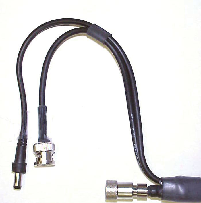
Table of Contents

MedRx OtoWizard System ________________________________________________1
Table of Contents _______________________________________________________2
Item Classification ______________________________________________________4
 Introduction to the MedRx OtoWizard System __________________________________ 4
OtoWizard Components __________________________________________________5
Description and Checklist ________________________________________________5
 Patient Hand Switch ________________________________________________________ 5
 Y-cord ___________________________________________________________________ 5
 Real Ear Measurements _____________________________________________________ 5
 Probe Microphone Assembly _________________________________________________ 5
 Light source and control box assembly_________________________________________ 5
 Camera/Probe assembly_____________________________________________________ 6
 Fiber optic and twin lead cable _______________________________________________ 6
 Coupler Microphone________________________________________________________ 6
 Reference Microphone ______________________________________________________ 6
 Coupler and Adaptors ______________________________________________________ 6
 Optional extras: ___________________________________________________________ 7
OtoWizard Assembly and Installation_______________________________________8
 Connecting and disconnecting the fiber optic cable to the camera probe ____________ 10
   To Connect ____________________________________________________________________ 10
   To Disconnect __________________________________________________________________ 10
   Insuring proper picture quality _____________________________________________________ 10
OtoWizard Connection Diagrams _________________________________________11
 Figure 1: System Front Panel _______________________________________________ 11
 Figure 2: System Left Side Panel ____________________________________________ 11
 Figure 3: System Back Panel ________________________________________________ 12
 Figure 3a: System Back Panel. Alternative patch cable connection ________________ 12
 Figure 4: Testbox Back Panel _______________________________________________ 13
 Figure 4a: Testbox Back Panel Alternative patch cable connection _______________ 13
 Figure 5: Inside Testbox ___________________________________________________ 13
 Using the deluxe hand held camera probe _____________________________________ 14
Care, Maintenance, and Storage__________________________________________15
 Cleaning _________________________________________________________________ 15
 Transportation and Storage__________________________________________________ 15

                                            2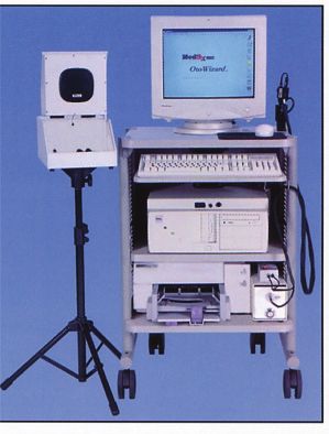
Trouble Shooting Guide ________________________________________________16
Limited Warranty ______________________________________________________17
Components Registration________________________________________________17
Technical Specifications ________________________________________________18
 OtoWizard Technical Specifications __________________________________________ 18
 OtoWizard Technical Specifications Continued ________________________________ 19
 Technical Specifications for the Video Otoscope ________________________________ 20

                                         3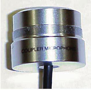
Item Classification

   Introduction to the MedRx OtoWizard System

   MedRx OtoWizard includes:

   •     Intel Pentium II 266 MHZ computer or
         higher                                     •   Bone conductor
   •     High resolution color monitor              •   MedRx color video camera
   •     Color printer                              •   MedRx deluxe 3mm Probe
   •     Monitor headset                            •   MedRx Video Otoscope control box
   •     Insert earphones                           •   Fiber optic variable 150 watt light source
   •     Coupler microphone                         •   3mm specula
   •     Reference microphone                       •   Fiber optic cable
   •     Battery pill simulators                    •   Wide angle lens
   •     Telecoil                                   •   Mobile cart
   •     Probe microphone                           •   Complete set of cables and necessary
                                                        attachments

Color Monitor

                                                                                      Video Camera and
                                                                                      Probe

HIT Test Box                                                                          Mouse

                                                                                      Keyboard

System                                                                                Fiber Optic Cable

                                                                                      Video Otoscope
Test Box Stand                                                                        Control/Box

                                                                                      Variable 150 Watt
Color Printer                                                                         Light Source

Mobile Cart

                                                4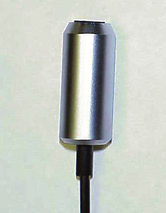
OtoWizard Components                                       Speakers
Description and Checklist                                  Two external speakers with adjustable volume
                                                           control and cable with ¼” jack connection to the
                                                           system.
System
                                                           Real Ear Measurements
DSS designated board; Intel Pentium II MMX 6.4             Probe Microphone Assembly
GB Hard Drive CD ROM 1.44MB or LS120                                           The probe microphone
Floppy disc drive; Input/Output peripheral                                     assembly contains the probe
connections                                                                    microphone port and the free
                                                                               field microphone and
Monitor
                                                                               connects to the system by an
Multimedia monitor                                                             8 pin connector
Keyboard
PS2 connection external keyboard
                                                           Ear Hook
Mouse
                                                           Three adjustable ear hooks. Clip one to the probe
PS2 connection external mouse                              microphone assembly case to hang over the
Mouse Pad                                                  patient’s ear for real ear measurements. Store the
                                                           remainder for future use.
Printer
                                                           Silicon probe tubes
Color printer and serial printer cable
                                                           Package of 50 replacement probe tubes with black
Power cords                                                collar rings.
Power cords (x 4) for AC connection to the power           Elbows
strip for the system (x2), monitor and printer.
                                                           Package of three plastic elbows used to assist in
Power Strip                                                positioning the probe tube in the patient’s ear
                                                           canal.
120V surge protected six or eight plug power
strip                                                      Monitoring Headset
Audiometry                                                 Proluxe headset with ¼” jack connector for
                                                           monitoring real ear measurements.
Insert earphones
                                                           Video Otoscope
Serialized and calibrated insert earphones package
with replacement tips and attachment clips                 Light source and control box assembly
                                                                              Light source with EJA 150
Bone Conductor                                                                lamp bulb and adjustable
Patient Hand Switch                                                           intensity control with mounted
                                                                              control box. The light source
Y-cord                                                                        connects to the system using
                            Split Y-cord with
                                                                              the jumper cable.
                            ¼”jack connector to
                            connect the bone
                            conductor and patient
                            hand switch to the             Jumper cable
                            system. Y-cord has a           12” long jumper cable connects the video control
                            red collar on one end          box to the pigtail video input cable
                            of the Y, and a blue
                            collar on the other end.

                                                       5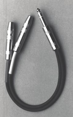
Pigtail video input cable                               Hearing Instrument Test Box
                          AV in video connector.        Test Box
                                                        Acoustic treated test box with loud speaker in the
                                                        hinged lid. The loud speaker is used as the
                                                        stimulus source for real ear measurements when
                                                        the lid is open and for test box measurements
                                                        when the lid is closed. The collar on the base of
                                                        the test box allows the test box to be mounted to
                                                        the tripod stand. The test box has internal
Control box power supply                                connections for the coupler and reference
2” x 1.5” x 2.25” black cube supplying 120 V AC         microphones and battery pill.
to the back of the control box from the power           Tripod stand
strip
                                                        Adjustable height tripod test box stand.
Camera/Probe assembly
                                                        Coupler Microphone
                                                                           Calibrated microphone to
                                                                           ensure precise stimulus levels.
                                                                           The coupler microphone is
                                                                           connected to a ¼” jack inside
                                                                           the test box.
    Serialized camera and probe are pre-
    assembled and located in a black foam
    packed case. The camera and probe are               Reference Microphone
    connected to the light source and control box                           The reference microphone is
    assembly using the fiber optic and twin lead                            used as the live speech input
    cable set.                                                              microphone and to ensure a
                                                                            precise input stimulus level in
Fiber optic and twin lead cable
                                                                            test box measurements. The
                                                                            reference microphone connects
                                                                            to the test box using a ¼”jack.

                                                        Coupler and Adaptors
                                                                                   2cc coupler and
                                                                                   adapters for Body Aid,
  The fiber optic and twin lead cable bundle is                                    ITE, ITC and BTE
  used to connect the camera and probe to the                                      hearing aids.
  front of the control box and light source.
Speculum, curettes and alcohol swabs                    Battery Pills
Package of reusable 3mm specula covers
                                                        Package of battery pills: 635, 312, 13, 10 and 5.
Camera stand                                            These are used to determine the hearing
                                                        instrument battery drain in the test box
Black camera stand and two screws to secure the         measurement task.
stand to the top shelf of the cart. The camera
stand stores the camera and probe assembly when
it is not in use.

                                                    6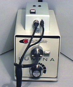
Fun tac                                                    Optional extras:
The fun tac is used to create an air tight seal when       Portrait options: Two options are
attaching an ITE, ITC or CIC hearing instrument            available for taking a photo of the patient.
to the coupler for test box measurements.
                                                                  Full-face camera lens is used in
Additional components                                      place of the probe on the Video Otoscope
                                                           camera. This requires the removal of the
Test box patch cable set                                   probe and placement of the Full-face lens
                                                           onto the camera.
A six foot cable bundle with five color-coded ¼”
jacks on each end. The patch cable connects the                    Quick-cam pro is a portrait
test box to the system or alternative 14-pin single        camera that is place on the top of the
patch cable.                                               monitor and is available at all times to
Mobile Cart                                                take a portrait of the patient.
A mobile cart with three shelves and adjustable
height keyboard shelf. Pull out storage drawer
beneath the lower shelf.                                   Backup options: Three options are
                                                           available for the backup of your database.
Hooks
                                                                   Floppy disk 3.5 /1.44MB internal
Two cart hooks are provided to secure to the cart
below the keyboard shelf. The hooks are used to            drive. You may use this floppy to backup
hang the Audiometry and Real Ear Measurement               your database however if may require
peripheral components when they are not in use.            many disk depending on the size of your
A set of screws and anthro tool are provided to            database.
secure the hooks to the cart.
                                                                   Hard disk 6.3G external drive
Sounds of Life CD                                          can be attached to your system via the
Auditec speech CD                                          parallel port and will allow you to backup
                                                           your database to the new disk drive.
Loudness Scaling panel
                                                           These optional extras are available
Rainbow passage panel
                                                           from your MedRx representative. Call
Accessory hooks                                            1-888-392-1234 for ordering and
Multi-media cables for the monitor                         installation information.

User’s Manual
Operating and Installation instructions
Software package
Calibration certificate

                                                       7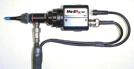
OtoWizard Assembly and Installation
The assembly instructions below provide a trouble free guide to installing the OtoWizard. Follow each
step in sequence and refer to the connection diagrams on the following pages for assistance in assembling
and installing the OtoWizard.

•   Unpack all of the boxes. Locate and identify          •    Connect a power cord to the monitor and
    each component as it is listed in the                      feed it through the shelf holes in the top and
    preceding component list.                                  middle shelf and plug it into the power strip.
•   Locate the mobile cart and attach the four            *Refer to the connection diagrams for the
    wheels to the base of the cart. Two of the            following directions:
    wheels have lock devices on them. These               • Feed the monitor serial cable through the
    wheels should be located on the front of the               top shelf hole and connect it to the monitor
    cart. Simply push the stem of the wheels                   port on the rear panel of the system as
    firmly into the sockets on the base of the                 indicated.
    cart and the wheels will lock into place.             • Connect the mouse to the rear panel after
•   Locate the anthro tool. This is used for the               first feeding the connector through the top
    screws on the cart, hooks and camera stand.                shelf to the cart. Locate the mouse pad and
•   Remove the four- (4) screws from the rear                  mouse on the top shelf to the right side of
    panel of the cart and remove the rear panel.               the monitor.
•   Place the keyboard on the keyboard shelf.             • Connect the keyboard to the system.
•   Adjust the keyboard shelf to its highest              • Connect the AV pigtail cable to the video IN
    position while still being able to slide the               jack.
    shelf easily.                                         • Connect the 12” jumper cable from the
•   Locate the package of two (2) hooks and                    camera control box to the yellow connection
    four (4) screws. Using the anthro tool,                    on the pigtail cable. Make sure you feed the
    attach a hook to each side of the cart just                cable through the hole in the middle shelf
    below the keyboard shelf.                                  before connecting it to the pigtail.
•   Attach the camera stand to the pre-drilled            • Plug the power cable from the back of the
    holes on the top shelf of the cart. Use the                light source into the power strip.
    anthro tool and the two- (2) screws                   • Connect the control box power supply to the
    provided.                                                  back of the control box and plug it into the e
•   Place the OtoWizard system on the middle                   power strip.
    shelf with the front of the system facing             • Connect the printer power supply to the
    forward.                                                   back of the printer and plug it into the power
•   Place the monitor on the top shelf.                        strip.
•   Feed the multimedia cable through the hole            • Connect the insert earphones to the left side
    in the top shelf after connecting the red and              of the system. Make sure the right (red)
    white pins to their corresponding inputs on                insert is connected to the red jack and the
    the back of the monitor.                                   left (blue) insert is connected to the blue
•   Place the light source/control box on the                  jack. It is an option to run the inserts
    right side of the bottom shelf as it appears in            through the back panel of the cart. ( see
    the photo in this document.                                instructions for using sound booth patch
•   After removing the tape from the paper trays               cables)
    on the printer and inserting the print                • Connect the Y-cord to the left side of the
    cartridges in the printer, place the printer on            OtoWizard Computer. Connect the bone
    the left side of the bottom shelf.                         conductor to the red connector and the
•   Working from the back of the cart, connect                 patient hand switch to the blue connector.
    a power cord to the back panel of the system
    and feed the plug down through the hole in
    the middle shelf to the power strip.              8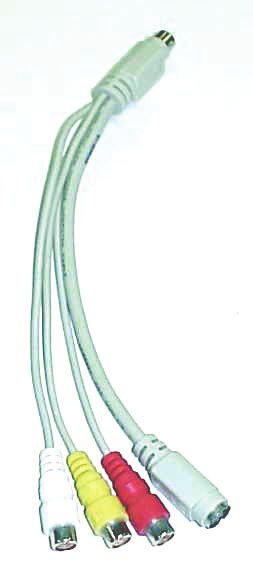
•   Hang the inserts, bone conductor, and                 •    Extend the legs of the tripod test box stand
    patient hand switch over the hook on the left              and tighten the adjustment knob. Raise the
    side of the cart or use the provided                       test box stand to a desired height and mount
    accessory hooks.                                           the test box on the tripod. Make sure all the
•   Connect the speakers to the ¼”jack                         adjustment knobs are tightened. Locate the
    connection marked HLS on the left side of                  test box stand to the left of the cart.
    the system. Position the speakers on the top          •    Connect the coupler microphone and
    shelf of the cart on either side of the                    reference microphones to the inside of the
    monitor.                                                   test box, as indicated in the connection
•   Plug the probe microphone into left 8-pin                  diagram in this manual for the test box. The
    connection on the front of the OtoWizard                   remaining jack connects the desired battery
    Computer.                                                  pill.
•   Connect an ear hook onto the probe                    •    Plug the printer cable into the printer. The
    microphone assembly by sliding it into the                 printer cable will feed out the lower hole in
    groove circling the probe microphone                       the back panel of the cart and re-enter
    assembly. Mold the hook into a U shape                     through the top hole in the back panel
    ready to hang over the patient’s ear.                      before being connected to the system.
•   Connect a silicon probe tube to the probe             •    Plug the patch cable into the rear panel on
    microphone port. Slide an elbow onto the                   the system matching the colors on the jacks
    silicon tube and hang the assembly on the                  to the cables, or inserting the 9-pin
    cart hook on the right side of the cart.                   connection in to the jack. The patch cable
•   Locate the video camera and probe                          will run through the hole on the back panel
    assembly. Use the fiber optic and twin lead                of the cart.
    cable to connect the camera and probe to the          •    Before replacing the back panel on the cart,
    front of the light source and control box, as              check to make sure all connections listed
    indicated in the connection diagram. Make                  above have been made. Make sure the
    sure the BNC connector is turned 1/8 of a                  power button on the system is in the on
    turn to secure it to the control box. Place                position (-) and the power strip is turned on.
    the camera in the stand on the top shelf of                Reattach the back panel. Remember to feed
    the cart.                                                  the patch cable through the top hole.
•   Insert the fiber optic into the light source          •    Connect the patch cable to the test box
    and secure it in place by adjusting the screw              matching the colors on the jacks to the
    set.                                                       cables.

** NOTE: Systems using NOAH will require
the connection of the HIPPO Box to the
"COM1" Serial Port on the back of the
computer.

Connecting to a Sound Booth
When using the patch cables to couple the system to a two way sound booth, connect the appropriate right
and left ear phone cables to the system. With the Y-cord connected to the system, plug in the respective
bone conductor and patient hand switch patch cables into the Y-cord. Connect the patch cables to the booth
and the inserts, bone conductor and patient hand switch to the patch cable panel on the inside of the booth.

Follow the Operating Instructions on the following pages to start using the OtoWizard.

                                                     9
Special Instructions
Connecting and disconnecting the fiber optic cable to the camera probe

         To Connect

Probe Light Source
Push the connector end into the probe as shown
on the right.

Video Cable
Align coupler, push in and turn to the right

Power Cable
Push in until cable stops

         To Disconnect

Probe Light Source                                               Fiber optic light source            Power Cable
With thumb and forefinger, pull down on the                                              Video Cable
connector shell then gently pull the connector
away from the probe.

Video Cable
To disconnect push in turn left gently pull the
connector away from the camera.
                                                          HINT: Turn the light source on at least 5
Power Cable                                               minutes before you use the camera to prevent the
With thumb and forefinger, pull out on the                lens from fogging when entering the warm
connector and remove the camera.                          environment of the ear canal.

Insuring proper picture quality
To insure proper picture quality, use an alcohol
wipe on the lens tip before and after each use.

Fuzzy Video Images
Cerumen and/or fog on the lens tip most often
cause fuzzy video images. You can correct or
prevent either condition by vigorously using an
alcohol wipe on the lens tip before and after use.

Attaching the Full Face Lens
Turn the light source off, disconnect the fiber
optic cable from the camera, unscrew the probe
from the camera and place the probe in the
camera stand. Screw in the full face lens. Do no
tighten unnecessarily.
NOTE: always face the camera away from
any light source when removing the probe or
full face lens.

                                                     10
OtoWizard Connection Diagrams
Figure 1: System Front Panel
Probe Microphone Volume control Power ON/OFF switch
3 1/2 Floppy
ystem Power button CD Rom
Figure 2: System Left Side Panel
Right AC(red) Left AC(blue)
Y-cord for Bone conductor and Patient Handswitch
Free Field speakers for HLS
11
OtoWizard Connection Diagrams cont….Figure 3: System Back Panel
Patch Cable connections to the testbox:
Battery Telecoil Speaker Reference Mic Coupler Mic
Black Brown Purple Green Grey
(AV IN)
Power cord com1 com2 Video in from Otoscope
Power on/off Monitor
Mouse Printer Multimedia sound from monitor
Keyboard
Figure 3a: System Back Panel. Alternative patch cable connection
Patch Cable connection to testbox
Power cord Single 14 pin cable
All other connections are the same as in Figure 3.
12
Otowizard Connection Diagrams cont….Figure 4: Testbox Back Panel
Grey Black Purple Brown Green
Coupler Battery Speaker Telecoil Reference Mic
Patch Cable Connections from the System Back Panel
Figure 4a: Testbox Back Panel Alternative patch cable connection
Single 14 pin patch cable connection from the System Back Panel
Figure 5: Inside Testbox
Reference Microphone Battery Pill Coupler Microphone
13Operating Instructions for the
MedRx OtoWizard System
Power Up
Ensure the power switch on the power strip and
the master power switch on the back of the
system are in the "on "position.
OtoWizard System Camera
The switch on the front of the computer turns the The camera power switch is located on the top of
system and monitor on at the same time. A green the camera control box. An indicator light turns
light on the system and monitor are indicators red when the power is on.
the power is on. A red light on the monitor
indicates it is in the standby mode. Suggested operating procedure for the video
Otoscope.
If your system has a separate power supply to Leave the camera on when it will be used within
the digital board, turn the power switch on for the next 10 to 15-minute period. Otherwise turn
the board. An orange illuminated switch the camera on and off as needed. The camera
indicates this power is on. becomes warm to touch after being left on for
several minutes. This won't shorten its life even
Printer if left on continuously. However turning the
The printer power switch is located on the front camera off when it is not in use will conserve
of the printer, lower left side. An indicator light power. The light source can be left on for long
turns green when the power is on and the printer periods of time, but the lamp intensity should be
is ready to print. turned down except when being used for
pictures. Following this guideline will greatly
Light Source extend the bulb life, which is estimated to be
Rotating the knob located on the front of the about 2500 hours. We suggest you keep a spare
light box controls the light source intensity. The bulb (EJA 150) on hand.
light source should be turned to 3/4 intensity.
Once the probe is in the patient's ear, you may
need to adjust the intensity control to achieve an
optimum picture. When in the standby mode,
leave the light on but turn the intensity down.
Using the deluxe hand held camera probe
Sometimes the lens is smeared with cerumen
CAUTION: The deluxe hand held camera and will need to be properly cleaned with an
probe/assembly is only to be used by a person alcohol wipe in order to provide a clear image.
qualified in the use of an Otoscope. Misuse can
cause a patient pain and possible ear damage. When inserting the probe in the ear canal, watch
The speculum cover is always to be used with the positioning, as you would a regular
the system. The speculum cover must be cleaned Otoscope, by looking directly at the patient’s ear
or replaced between usage per accepted medical canal as you pull back the pinna. Once you have
practice procedures. the probe in the viewing position, then look at
the monitor.
Prior to inserting the probe in the ear canal, hold
the probe within 1/4" of a known object, such as
your finger, to check the quality of the image.
14Care, Maintenance, and Storage
Your MedRx OtoWizard has been designed to Transportation and Storage
provide years of trouble-free service. Do not
remove or open the cabinets of the equipment, as When transporting or storing your video
there are no user serviceable components inside. Otoscope, it is best to use the original hard side
travel cases, otherwise use the original packing
Cleaning case or similar packaging. Store the system in a
cool, dry location and do not place your system
To keep your system looking new, wipe the in direct sunlight. Care must be taken to protect
exterior of the components with a soft cloth. the system from shock, moisture damage and
Stubborn stains may be removed using a cloth mishandling. Do not place heavy objects on any
moistened with water and mild detergent. Do not of the system's components.
allow debris or fluid to enter in the components.
Use an alcohol wipe to clean the lens on the end To assure proper operation and warranty
of the Otoscope probe. protection, use manufacturer's replacement
components only.
For proper care of the video monitor and printer,
please refer to their respective operator's manual
(included in the original packaging)
15Trouble Shooting Guide
Problem Main Cause Solution
Fuzzy or out of focus picture Dirty probe tip (dried) cerumen Vigorously clean tip with an alcohol wipe
Blue video screen Camera not turned on Check all connections on camera control
box and power switch is illuminated red
No light from probe tip Light source not on Turn on light source
Bulb burnt out Replace Bulb
Indicator light switch on control box not on Power supply not plugged in or Plug in power supply or
Short in twin cable Unplug twin cable from control box.
See if light comes on, if so replace twin
cable
No Display on Monitor Monitor not turned on or not plugged in Check plug and on/off switch on front of
monitor
Insert Ear Phones have no sound Not plugged in Check all jacks for secure plug in
No Sound from HLS speakers Not plugged in or turned off Check all plugs
Volume set to low Check volume setting
OtoWizard will not turn on Not plugged in or Plug computer in
Surge protector not set Reset surge protector
Separate power switch on DSS board is Close OtoWizard program, turn DSS
WrongDspKey not turned on power switch on and re-open Otowizard
Rem Run Error 255 Peripherals are not plugged in properly Check all plugs on the side and front of
the computer
Quick calibration check
To check the system calibration, arrange the probe microphone as you would to calibrate a probe tube (the
probe tube is up against the free field reference microphone), select the REAR test in the REM menu, hold
the probe assembly 12 inches from the speaker and select START. You should see a reasonably flat line
at the input stimulus level.
* Where else to get HELP
• Technical support at MedRx
• Online support at MedRx Webster "Medrx@Medrx-USA.com"
16Limited Warranty
MedRx, Inc warrants the OtoWizard System MedRx will at it’s discretion, service and repair
to be free from defects in material and out of warranty components at the purchaser’s
workmanship for one year from the time of request, charging for parts and labor as
purchase. If this system fails to perform as necessary.
specified during this period, the purchaser is
responsible for calling MedRx at (888) 392-
1234. The company’s representative will advise The limited warranty is deemed void if software
the owner to either return specific components or or hardware is installed on the OtoWizard which
the entire system to: is not pre-approved by MedRx, Inc. Approved
software includes NOAH and HIMSA approved
MedRx Inc. hearing aid manufacture programming modules
1200 Starkey Road, #105 for fitting hearing aids. Installation of HIPRO
Largo, FL 33771 box is approved.
MedRx will repair or replace any defective parts,
fully test and calibrate the system and/or MedRx, Inc is not responsible for problems
components and ship the system promptly back resulting from installation of unapproved
to the owner. There is no cost for this warranty software or hardware. In the event of
service, provided the system is one year old or unapproved software or hardware installed on
less and has not been misused, abused or the system causing a conflict with the OtoWizard
damaged. Such damage includes, but is not functions, MedRx will service the problem for a
limited to, dropping, exposure to excessive heat fee to be determined at the time of service.
greater than 100ºF and water/liquid damage.
Repair or replacement of the system as provided MedRx has supplied with every system
under this warranty is the sole and exclusive Microsoft Backup. MedRx strongly recommends
remedy of the purchaser. MedRx shall not be that you backup your database daily to insure no
liable for any consequential or incidental loss of data.
damages, or for breach of any express or implied Consult your MedRx Technical support member
warranty. Except to the extent of applicable law, for other alternatives for back up.
any implied warranty, merchantability or fitness
of this product is limited to the duration of this
warranty.
Components Registration .
For Customer Information
OtoWizard Serial Number
Probe Serial Number Light Serial Number
Camera Serial Number Insert Ear Phone Left
Date Purchased Insert Ear Phone Right
17Technical Specifications
OtoWizard Technical Specifications
Computer Mobile Cart
Intel Pentium II 266 (or above) Sturdy construction, 300 lb. + capacity
64MB 8x64 Memory Three shelf standard + Keyboard Shelf
Western Digital HD 6.4GB 115lbs. (Approx.) weight
Toshiba CD-ROM 24x IDE Six outlet power strip installed
1.44MB Floppy Disk or Color matched to printer/monitor Rolling/lockable
LS120 Floppy Disk castors
USR 56k INT. Fax Modem 25" (w) x 37" (h) x 21.5" (d)
ATI Video card 4MB (or above) Six or eight outlet power strip
External Keyboard PS2 connector
External Mouse PS2 connector HIT Box
Weight 15lbs. 14" (L) x8" (w) x 10" (h)
17.5" (l) x17.5" (w) x 6" (h) Weight 3lbs.
Damping Treatment Acoustic Damping
Power supply Universal Microphones Electret
Input100-120/220-240v 50/60HZ
Output 250W +/-15V External Speakers
Output Power 2.5 watts RMS per
Color Printer speaker
HP DeskJet 697c Color printer (or Above) Frequency Response 100 to 18,00Hz
Printer speed Dimensions 7' x 3 3/8" x 4 5/8"
Black & White Power Supply 9 Volts DC output
Best mode 1 minute per page 600x600 DPI
Normal mode 3 minutes per page 600x300 DPI Insert Earphones
Econo mode 5 minutes per page 300x300 DPI E-A-RTONE 3ATM Specifications:
Color 1kHz Sensitivity 102.5 dB SPL
Best mode .3 minute per page 600x600 DPI HA2cc coupler type BTE-2
Normal mode .8 minutes per page 600x300 DPI @0.1 Volt RMS (10 Ohms)
Econo mode 1.7 minutes per page 300x300 DPI Limits +/-3 dB
Large selection of Fonts Impedance 1 Ohms
Max Operating Temperature 41ºF-104ºF Max Output Meets or exceeds 110dB HL at
Humidity 10-80% RH non-condensing Standard audiometric frequencies
Recommended operating conditions Between 250-6000 Hz
Temperature 59ºF-95ºF Safe Operating Limits Max continuous sine wave
Humidity 20-80% RH non-condensing drive:
Storage Temperature 2.5 Volt RMS (10 Ohms)
Temperature 40ºF-140ºF Maximum Peak voltage
For 1% duty cycle 10 Volt
Accessories 50 disposable E-A-RINKTM 3A eartips
Proton Color Video Monitor 50 disposable E-A-RINKTM 3B eartips
17" tube 15.9 Diagonal 213 cm cord
Dot Pitch 0.28mm Left and right ¼” mono color coded
Dual video inputs phono-plugs
VESA 1280 x 1024 60Hz Date Supplied 2cc-coupler frequency response on
AC 110-240V, 50/60Hz individual Units
Video signal 30-70 KHz Meets IEC type 4 and ANSI S3.6-1989
39.2 lbs. (Approx.) weight standards
Speaker Output 2 Watts (RMS) / CH
18OtoWizard Technical Specifications
Continued DSS Board
Battery Simulator Weight 2lbs.
Voltage supply 0-3.5V in 20mV steps 17" (L) x17" (w) x 3.5" (h)
Impedance 0.1-25 Ohms in 0.1 Ohm steps Probe Channel A and B Measurements:
Measuring Range 100uA-50mA Frequency Range 42-15600Hz
Resolution maximum 5uA Frequency Resolution 1/24 Octave
Accuracy +/-15V Dynamic Range 130dB
Battery Pills Type 13,312,675,A10, A5 Dynamic Resolution 0.25 dB
Accuracy +/-0.2dB
Reference Micriphone Noise Floor 10dB SPL
TM 12REF
Probe Channel A and B output circuit:
Probe Microphone Frequency Range 50-15000Hz
PM 12 Dynamic Range 120dB
Loudspeaker Output min 6W in 4 Ohms
Bone conductor Loop Control (A only) mim 1A in 2 Ohms
B-71 bone conductor TDH electricalTechnical Specifications for the Video Otoscope
Video Camera Deluxe Probe
• 1/3 inch pick-up element • Field of view 60º
• 420K pixels • Focal plane from tip .25" (+/-.125")
• Horizontal resolution 420 TV lines • 360º glass fiber light at tip
• 5 lux minimum illumination • Conventional optical elements, color corrected
• CS lens mount • Minimum intensity 750 FC at 1"
• Total weight 153 grams • Working length 1.125" from shoulder
• Adjustable white balance • Tip diameter .120"
• -10º to +40ºC operating temperature • Tapered tip to .235" diameter
• 42 (W) x 42 (H) x 53 (L) mm • Aluminum body
• BNC video output socket • Serialized
• 12V DC +/- 10% voltage requirement • Integral glare reduction filter
• Total weight 50 grams
Fiber Optic Light Source • Normal erect image orientation
• 150 watt • Overall length 3.22"
• Infinitely variable • Body diameter .7"
• Thermal overload protected • Maximum diameter 1.225" dia.
• Fan cooled • Accepts Welsh Allyn 24303 series reusable
• 3 amp circuit breaker specula 3, 4, or 5mm
• EJA reflector lamp • Stainless steel probe tip
• 115 VAC or 220 VAC (optional) • Swivel mount
• 4 ¾" (w) 6 ¼" (h) 9 ½" (d) • LEMO FFA.OS fiber optic socket
• On/off switch incorporated in intensity control • CS mount
• Can be cleaned with alcohol
Note: The camera and probe are sold as a matched system with MedRx proprietary coupling and focusing
techniques. Should either the camera or probe become defective either part can be replaced; however, the
process must be accomplished at the MedRx USA manufacturing facility. Neither the probe nor the camera
can be sold separately. The camera and probe are a matched set and are not sold separately.
20You can also read