APPLICATION OF BA0.5SR0.5TIO3 (BST) FILM DOPED WITH 0%, 2%, 4% AND 6% CONCENTRATIONS OF RUO2 AS AN ARDUINO NANO-BASED BAD BREATH SENSOR - MDPI
←
→
Page content transcription
If your browser does not render page correctly, please read the page content below
chemosensors

Article
Application of Ba0.5Sr0.5TiO3 (Bst) Film Doped with
0%, 2%, 4% and 6% Concentrations of RuO2 as an
Arduino Nano-Based Bad Breath Sensor
Irzaman 1, *, Ridwan Siskandar 2 , Brian Yuliarto 3 , Mochammad Zakki Fahmi 4 and Ferdiansjah 5
 1   Physics Department, IPB University, Bogor, West Java 16680, Indonesia
 2   Computer Engineering Study Program, College of Vocational Studies, IPB University,
     Bogor, West Java 16151, Indonesia; ridwansiskandar@gmail.com or ridwansiskandar@apps.ipb.ac.id
 3   Engineering Physics Department, Bandung Institute of Technology, Bandung,
     West Java 40132, Indonesia; brian@tf.itb.ac.id
 4   Chemistry Department, Airlangga University, Surabaya,
     East Java 60115, Indonesia; m.zakki.fahmi@fst.unair.ac.id
 5   Nuclear and Technical Physics Department, Gadjah Mada University, Yogyakarta 55281, Indonesia;
     ferdiansjah@ugm.ac.id
 *   Correspondence: irzaman@apps.ipb.ac.id

 Received: 16 October 2019; Accepted: 13 December 2019; Published: 25 December 2019

 Abstract: Ba0.5 Sr0.5 TiO3 (BST) film doped with variations in RuO2 concentration (0%, 2%, 4%, and 6%)
 has been successfully grown on a type-p silicon substrate (100) using the chemical solution deposition
 (CSD) method and spin-coating at a speed of 3000 rpm for 30 s. The film on the substrate was
 then heated at 850 ◦ C for 15 h. The sensitivity of BST film + RuO2 variations as a gas sensor were
 characterized. The sensitivity characterization was assisted by various electronic circuitry with the
 purpose of producing a sensor that is very sensitive to gas. The responses from the BST film +
 RuO2 variation were varied, depending on the concentration of the RuO2 dope. BST film doped
 with 6% RuO2 had a very good response to halitosis gases; therefore, this film was applied as the
 Arduino-Nano-based bad-breath detecting sensor. Before it was integrated with the microcontroller,
 the voltage output of the BST film was amplified using an op-amp circuit to make the voltage output
 from the BST film readable to the microcontroller. The changes in the voltage response were then
 shown on the prototype display. If the voltage output was ≤12.9 mV, the display would read “bad
 breath”. If the voltage output >42.1 mV, the display would read “fragrant”. If 12.9 mV < voltage
 output ≤ 42.1 mV, the display would read “normal”.

 Keywords: Ba0.55 Sr0.45 TiO3 (BST) film; RuO2 ; bad breath gas sensor; op-amp; Arduino Nano

1. Introduction
     Halitosis is a general term to describe the presence of an unpleasant odor when exhaling [1].
Halitosis is caused by food debris left in the mouth, which is processed by the normal flora in the oral
cavity, such as protein hydrolysis by Gram-negative bacteria [2,3]. Oral conditions such as the decreased
flow of saliva, the blocked flow of saliva, the increase in the number of anaerobic Gram-negative
bacteria, the increase in food proteins, a more-alkaline oral cavity pH, and an increased number of
dead and necrotic cells in the mouth could also trigger bad breath [4].
     The discovery of volatile sulfur compounds (VSCs) which are believed to be the main cause of
halitosis has piqued the interest of many researchers in conducting studies related to them. VSCs
are a product of anaerobic bacterial activities and react with protein in the mouth from food debris
that contains protein, dead blood cells, dead bacteria, or epithelial cells which have sloughed off

Chemosensors 2020, 8, 3; doi:10.3390/chemosensors8010003                www.mdpi.com/journal/chemosensors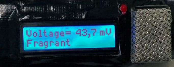
Chemosensors 2020, 8, 3                                                                                 2 of 11

Chemosensors 2020, 8, x FOR PEER REVIEW                                                             2 of 11
the oral mucosa [1]. VSCs are volatile sulfuric compounds which are formed through bacterial
reactions (especially anaerobic bacteria) with proteins, which are broken down into amino acids.
(especially anaerobic bacteria) with proteins, which are broken down into amino acids. There are
There are three amino acids that produce VSCs, cysteine, which produces hydrogen sulfide (H2 S),
three amino acids that produce VSCs, cysteine, which produces hydrogen sulfide (H2S), methionine,
methionine, which produces methyl mercaptan (CH3 SH), and cystine, which produces dimethyl
which produces      methyl mercaptan (CH3SH), and cystine, which produces dimethyl Sulfide
Sulfide (CH3 SCH3) [5].
(CH3SCH3) [5].
     Ferroelectric materials have the ability to change the direction of their internal electric currents,
     Ferroelectric materials have the ability to change the direction of their internal electric currents,
can be spontaneously polarized, and demonstrate a hysteresis effect which is related to dielectric
can be spontaneously polarized, and demonstrate a hysteresis effect which is related to dielectric
shifts in responding to the internal electricity field [1–3]. The hysteresis properties and high dielectric
shifts in responding to the internal electricity field [1–3]. The hysteresis properties and high dielectric
constant can be applied to the dynamic random access memory (DRAM) cell with a storage capacity of
constant can be applied to the dynamic random access memory (DRAM) cell with a storage capacity
over 1 Gbit; the piezoelectric properties can be utilized as a microactuator and sensor; the pyroelectric
of over 1 Gbit; the piezoelectric properties can be utilized as a microactuator and sensor; the
properties can be applied in the infrared sensor; the electro-optic properties can be applied in the
pyroelectric properties can be applied in the infrared sensor; the electro-optic properties can be
infrared thermal switch; and the polarizability can be applied as a non-volatile ferroelectric random
applied in the infrared thermal switch; and the polarizability can be applied as a non-volatile
access memory (NVFRAM) [6–8].
ferroelectric random access memory (NVFRAM) [6–8].
     BST film can be produced using fairly simple equipment on a tight budget and in relatively
     BST film can be produced using fairly simple equipment on a tight budget and in relatively short
short time [9–11]. In the film-producing process, there are a number of methods that could be used
time [9–11]. In the film-producing process, there are a number of methods that could be used such as
such as the metalorganic chemical vapor deposition (MOCVD) method [12–14], the chemical vapor
the metalorganic chemical vapor deposition (MOCVD) method [12–14], the chemical vapor
deposition method [15], the sol-gel method [16–19], the atomic layer deposition (ALD) method [20],
deposition method [15], the sol-gel method [16–19], the atomic layer deposition (ALD) method [20],
the pulsed laser ablation deposition (PLAD) method [21,22], rf sputtering [17,23,24], and chemical
the pulsed laser ablation deposition (PLAD) method [21,22], rf sputtering [17,23,24], and chemical
solution deposition (CSD) method [24–31]. The CSD method is superior as it can control the film
solution deposition (CSD) method [24–31]. The CSD method is superior as it can control the film
stoichiometry with good quality, an easy procedure, and has a fairly affordable cost [32–34]. The CSD
stoichiometry with good quality, an easy procedure, and has a fairly affordable cost [32–34]. The CSD
method is a method of making thin films by deposition of a chemical solution onto a substrate then
method is a method of making thin films by deposition of a chemical solution onto a substrate then
preparation through spin-coating at a certain rotational speed [35]. The CSD method has long been
preparation through spin-coating at a certain rotational speed [35]. The CSD method has long been
developed for growing thin film perovskite, since the 1980s [36].
developed for growing thin film perovskite, since the 1980s [36].
2. Research Method
2. Research Method
2.1. Preparation of the Type-p Silicon (100) Substrate
2.1. Preparation of the Type-p Silicon (100) Substrate
      The substrate used was type-p silicon (100). The substrate was cut into 4 squares sized 1 × 1 cm as
seen The   substrate
      in Figure       usedcutting,
                 1. After   was type-p   silicon (100).
                                   the substrate        The substrate
                                                  was washed   with 5%was cut into 4 squares
                                                                        hydrofluoric         sized
                                                                                      acid (HF)    1 × 1with
                                                                                                mixed    cm
as
2%seen   in Figure
    aquadest   [37]. 1. After cutting, the substrate was washed with 5% hydrofluoric acid (HF) mixed
with 2% aquadest [37].

                                                                                           2 squares.
                          Figure 1. The
                          Figure 1. The type-p
                                        type-p silicon
                                               silicon (100)
                                                       (100) substrate
                                                             substrate cut  into 11 ×× 1 cm2 squares.
                                                                       cut into

2.2. Preparation of the Ba0.5 Sr0.5 TiO3 Film Doped with RuO2 Solution
2.2. Preparation of the Ba0.5 Sr0.5TiO3 Film Doped with RuO2 Solution
      The Ba0,5 Sr0,5 TiO3 solution doped with RuO2 0%, 2%, 4% and 6% grown on the substrate using the
      The Ba0,5Sr0,5TiO3 solution doped with RuO2 0%, 2%, 4% and 6% grown on the substrate using
CSD method was made from 0.3512 g of barium acetate [Ba(CH COOH) , 99%], 0.2314 g of strontium
the CSD method was made from 0.3512 g of barium acetate3 [Ba(CH23COOH)2, 99%], 0.2314 g of
acetate [Sr(CH3 COOH)2 , 99%)], 0.7105 g of titanium isopropoxide [Ti(C12 O4 H28 ), 99%], and 2.5 mL
strontium acetate    [Sr(CH3COOH)2, 99%)], 0.7105 g of titanium isopropoxide [Ti(C12O4H28), 99%], and
of 2-methoxyethanol [H3 COOCH2 CH2 OH, 99%] as the solvent, and all the ingredients were then
2.5 mL of 2-methoxyethanol         [H3COOCH2CH2OH, 99%] as the solvent, and all the ingredients were
sonicated in a Branson model 2210 sonicator for 1 h (the resulting mixture is called the precursor) [38].
then sonicated in a Branson model 2210 sonicator for 1 h (the resulting mixture is called the precursor)
[38].

2.3. Growing the Ba0.5Sr0.5TiO3 Film Doped with RuO2
     The film-growing process was conducted using a spin-coating reactor, where the type-p silicon
substrate that had been washed was placed on the spin coating reactor plate which had had a piece
of double-sided tape affixed to the center. Next, 1/3 of the surface of the type-p silicon substrate that
Chemosensors 2020, 8, 3 3 of 11
2.3. Growing the Ba0.5 Sr0.5 TiO3 Film Doped with RuO2
The film-growing
Chemosensors process
2020, 8, x FOR PEER was
REVIEW conducted using a spin-coating reactor, where the type-p silicon 3 of 11
Chemosensors 2020, 8, x FOR PEER REVIEW 3 of 11
substrate that had been washed was placed on the spin coating reactor plate which had had a piece of
had been affixed
double-sided tapeto the spin
affixed coating
to the center.reactor
Next, plate
1/3 ofsurface was of
the surface covered withsilicon
the type-p seal tape. The seal
substrate thattape
had
had been affixed to the spin coating reactor plate surface was covered with seal tape. The seal tape
was
been used
affixedto prevent
to the spin the type-p
coating silicon
reactor substrate
plate surfacesurface
was from
covered being
with entirely
seal covered
tape. The by
seal the was
tape BST
was used to prevent the type-p silicon substrate surface from being entirely covered by the BST
solution,
used and thethe
to prevent double-sided
type-p silicon tape was used
substrate to make
surface fromsure
beingtheentirely
substrate did not
covered by slip
the off the plate
solution, and the double-sided tape was used to make sure the substrate did not slipBST solution,
off the plate
when
and the
the spin-coating
double-sided reactor
tape was was
usedoperated.
to make sure the substrate did not slip off the plate when the
when the spin-coating reactor was operated.
The substrate
spin-coating reactor that
was had been placed on the spin-coating reactor plate was dripped upon with 3
operated.
The substrate that had been placed on the spin-coating reactor plate was dripped upon with 3
dropsThe substrate
of BST that then
solution, had been placed on the
the spin-coating spin-coating
reactor was spun reactor plate
at 3000 rpmwas fordripped
30 s. Theupon with
dripping
drops of BST solution, then the spin-coating reactor was spun at 3000 rpm for 30 s. The dripping
3 drops was
process of BST solution,
repeated thenwith
3 times the spin-coating
a 60-second gap reactor was each
between spunrepeat.
at 3000After
rpm dripping,
for 30 s. The dripping
the substrate
process was
process was repeated
repeated33 times
times with
with aa 60-second
60-second gap gap between
between each
each repeat.
repeat. After
After dripping,
dripping, the
the substrate
substrate
was collected using tweezers [37]. Process Growing the Ba0.5Sr0.5TiO3 Film Doped with RuO2
was collected
was collectedusing
usingtweezers
tweezers [37].
[37]. Process
Process Growing
Growing the Ba0.5Sr0.5TiO3
the Ba0.5Sr0.5TiO3 Film Doped
Film Doped withshown
with RuO2 RuO2
shown
in Figurein 2.
Figure 2.
shown in Figure 2.
Figure
Figure 2. Process
2. Process Growingthe
Growing theBa0.5Sr0.5TiO3
Ba0.5Sr0.5TiO3 Film
FilmDoped
Dopedwith
withRuO2.
RuO2.
Figure 2. Process Growing the Ba0.5Sr0.5TiO3 Film Doped with RuO2.
2.4. The Annealing Process
2.4. The Annealing Process
2.4. The Annealing Process
The purpose of the annealing process was to diffuse the BST solution with the substrate.
The purpose of the annealing process was to diffuse the BST solution with the substrate. The
TM-3-130
The purpose
The annealing of the
process wasannealing
conductedprocess was to
gradually diffuse
using the
a Vulcan BST solution
modelwith the substrate.
furnace. The
The heating
annealing process was conducted gradually using a Vulcan TM-3-130model furnace. The heating
TM-3-130
◦ began
annealing process was conducted gradually using a Vulcan model furnace. The
began at room temperature and was raised to the required annealing temperature, 850 C, with an heating began
at room temperature and was raised to the required annealing temperature, 850 °C, with an adjusted
◦ C/min),
at room temperature
adjusted temperatureandrise was
(1.7 raised to the
andrequired
then the annealing
annealing temperature,
temperature was850 °C, with an adjusted
maintained for 15 h.
temperature rise (1.7 °C/min), and then the annealing temperature was maintained for 15 h. Next,
temperature
Next, furnacerise (1.7 °C/min),
cooling and then
was conducted the
until annealing
room temperature
temperature was maintained
was reached again [37]. for
The15 h. Next,
annealing
furnace cooling was conducted until room temperature was reached again [37]. The annealing
furnace can
process cooling was
be seen conducted
in Figure 3. until room temperature was reached again [37]. The annealing
process can be seen in Figure 3.
process can be seen in Figure 3.
Figure 3. The annealing process.
Figure 3. The
Figure 3. The annealing
annealing process.
process.
2.5. Contact
2.5. Contact Installation
Installation in
in the
the Ba
Ba0.5 Sr0.50.5
0.5Sr TiOTiO
33 FilmDoped
Film Dopedwith
withRuO
RuO 2 2
2.5. Contact Installation in the Ba0.5Sr0.5TiO3 Film Doped with RuO2
The contact
The contactholes
holesininthe
thefilm
filmwere
were made
made 2 ×2 2×mm
asas 2 mmsquares
squares on onthethe
BSTBSTlayer andand
layer the remaining part
the remaining
The contact holes in the film were made as 2 × 2 mm squares on the BST layer and the remaining
of theof
part BSTthefilm wasfilm
BST covered
was using
covered aluminum foil. The next
using aluminum process
foil. The was nextaluminum
process was (Al) aluminum
metallization as
(Al)
part of the BST film was covered using aluminum foil. The next process was aluminum (Al)
the contact medium for the film which was done by evaporation in
metallization as the contact medium for the film which was done by evaporation in a vacuum a vacuum container. And then the
metallization as the contact medium for the film which was done by evaporation in a vacuum
hidder andAnd
container. thin then
copperthewire were
hidder andaffixed
thin using
copper silver
wirepaste
were[37].
affixedTheusing
process of aluminum
silver paste [37].metallization
The process
container. And then the hidder and thin copper wire were affixed using silver paste [37]. The process
as the
of film’s contact
aluminum mediumascan
metallization thebefilm’s
seen in Figuremedium
contact 4. The Ba 0.5 Sr
can TiO3 in
be0.5seen film doped
Figure 4. with
The RuO 2 model,
Ba0.5Sr0.5TiO3
of aluminum metallization as the film’s contact medium can be seen in Figure 4. The Ba0.5Sr0.5TiO3
film doped with RuO2 model, the result of the copper wire installation, and the physical appearance
film doped with RuO2 model, the result of the copper wire installation, and the physical appearance
of the Ba0.5Sr0.5TiO3 film doped with RuO2 and the physical appearance of the Ba0.5Sr0.5TiO3 film doped
of the Ba0.5Sr0.5TiO3 film doped with RuO2 and the physical appearance of the Ba0.5Sr0.5TiO3 film doped
with RuO2 can be seen in Figure 5.
with RuO2 can be seen in Figure 5.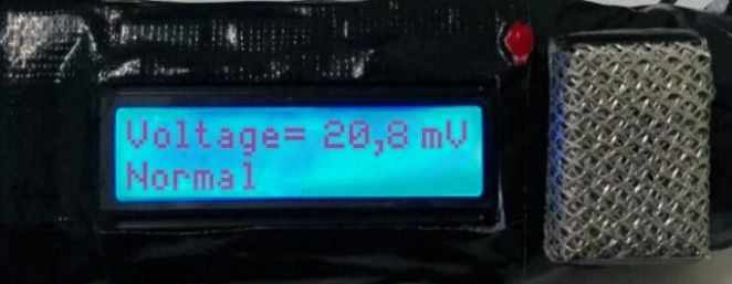
Chemosensors 2020, 8, 3 4 of 11
the result of the copper wire installation, and the physical appearance of the Ba0.5 Sr0.5 TiO3 film doped
with RuO2 and the physical appearance of the Ba0.5 Sr0.5 TiO3 film doped with RuO2 can be seen in
Chemosensors 2020, 8, x FOR PEER REVIEW 4 of 11
Figure 5. 2020, 8, x FOR PEER REVIEW
Chemosensors 4 of 11
Figure 4. The aluminum metallization process as the film’s contact medium.
Figure 4. The
The aluminum
aluminum metallization process as the film’s contact medium.
(a)
(a)
(b) (c)
(b) (c)
Figure 5.5. (a) The
Figure The Ba
Ba0.5
0.5Sr0.5
0.5TiO
TiO33 film
film doped
doped with
with RuORuO22 model;
model; (b)
(b) The
The result of the copper
copper wire
wire
Figure 5. (a)
installation; (c)
installation; The
(c)TheBa Sr
Thephysical TiO film
physicalappearance
0.5 0.5 doped
appearanceof
3 ofthewith
theBa
Ba0.5RuO model;
0.5TiO
0.5Sr0.52TiO33film (b) The
filmdoped result
dopedwith
withRuO of the
RuO22. . copper wire
installation; (c) The physical appearance of the Ba0.5Sr0.5TiO3 film doped with RuO2.
2.6. Characterization of the Ba0.5 Sr0.5 TiO3 Film Doped with RuO2 as a Bad Breath-Gas Sensor
2.6. Characterization of the Ba0.5Sr0.5TiO3 Film Doped with RuO2 as a Bad Breath-Gas Sensor
2.6. Characterization
Characterization of the Ba0.5Ba
of the Sr0.5TiO 3 Film Doped with RuO2 as a Bad Breath-Gas Sensor
Sr0.5 TiO3 film doped with RuO2 included characterization of its
Characterization of the Ba0.5 0.5Sr0.5TiO3 film doped with RuO2 included characterization of its
sensitivity as a bad
Characterization breath-gas sensor.
of the Basensor.
0.5Sr0.5TiO Thefilm
sensitivity
dopedofof Ba RuO
with Sr0.52 TiO 3 film doped
included with RuO asits
characterization a
sensitivity as a bad breath-gas The3 sensitivity Ba0.50.5
Sr0.5TiO 3 film doped with RuO2 as 2of a bad
bad breath-gas
sensitivity sensor was demonstrated by the difference in output voltage and the input voltage
breath-gasassensor
a bad was
breath-gas sensor. The
demonstrated by sensitivity
the differenceof Bain
0.5Sr 0.5TiO3 voltage
output film doped andwiththe RuO input 2 as a bad
voltage
(exposure
breath-gas tosensor
halitosis
was gases), (∆V/∆G),by
demonstrated with
the Vdifference
as the output in voltagevoltage
output and G and the input
the voltage
input with
voltage
(exposure to halitosis gases), (∆V/∆G), with V as the output voltage and G the input voltage with
exposure
(exposure to halitosis gases. The greater the voltage difference, the more sensitive the film is considered
exposure to to halitosis
halitosis gases),
gases. (∆V/∆G),
The greater withtheV as the output
voltage voltagethe
difference, andmore G thesensitive
input voltage the filmwith is
to be.
exposure to halitosis gases. The greater the voltage difference, the more sensitive the film is
considered to be.
considered to be.
2.7. Equipment Design
2.7. Equipment Design
2.7. Equipment
The prototypeDesignwas designed to be portable. The prototype design was 7 cm in length, with a
The prototype was designed to be portable. The prototype design was 7 cm in length, with a 6-
6-cm-diameter
The prototypehandle,
was 3-cm-diameter
designed to be lid, and 1-cm lidprototype
height, and the Ba 0.5 Sr70.5 TiO film doped
in33 length, withwith
cm-diameter handle, 3-cm-diameter
2 lid,portable.
and 1-cm The lid height, and design
the Bawas 0.5Sr cm
0.5 TiO film doped a 6-
with
RuO2 itself was
cm-diameter 2 × 33-cm-diameter
handle, cm 2. These measurements
lid, and 1-cm were
lid madeand
height, according
the Ba toSrthe requirements
TiO film doped ofwith
the
RuO2 itself was 2 × 3 cm . These measurements were made according to the requirements of the 0.5 0.5 3
RuO 2 itselfcomponents
electronic was 2 × 3 cm 2. These measurements were made according to the requirements of the
contained by the prototype design. The prototype design sketch can be seen
electronic
in Figure 6.components contained by the prototype design. The prototype design sketch can be seen
in Figure 6.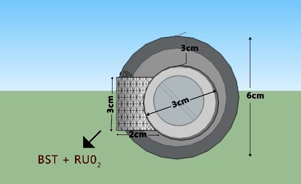
Chemosensors 2020, 8, 3 5 of 11
electronic components contained by the prototype design. The prototype design sketch can be seen
in Figure
Chemosensors 2020,6.
Chemosensors 8,2020,
x FOR8, xPEER
FOR REVIEW
PEER REVIEW 5 of 115 of 11
(a) (a) (b) (b)
Figure
FigureFigure The prototype
prototype
6. The6.prototype
The design:
design: (a)view;
(a) front
design: (a) front view;
front view;
(b) (b)view.
Side
(b) Side view.
Side view.
The components
The components
The components used usedused
in theininbad-breath
the bad-breath
the bad-breath
detectordetector prototype
prototype
detector consisted
consisted
prototype of theof
consisted ofinput
the input
the input component,
component,
component,
the processing
the processing component,
component,
the processing component, and
and output output
and output component.
component.
component. The
The input input component
component
The input is shown
is shown
component in Figure
in Figure
is shown 7, label
7, label
in Figure ‘a’,
7, label
the
‘a’, the Ba
‘a’, Ba
the
0.5 Sr
0.5SrBa0.5
0.5 TiO
TiO
0.5Sr0.5 film
33TiO doped
film3 film
doped with
doped RuO
with with
RuO 6%.
2 2RuO The processing
6%.2 The
6%. The component
processing used
component
processing a
component 10-bit microcontroller
used useda 10-bit
a 10-bit
(Figure 7, labeled
microcontroller
microcontroller(Figure ‘b’),
(Figure the7,ATMega138/Arduino
7, labeled ‘b’), the
labeled Nano which is
‘b’),ATMega138/Arduino
the ATMega138/Arduino Nano cm2 in
3 × Nano
1which issize.
which 1The
3 × is 3 ×output
cm 2 in size.
1 cm2 in component
The
size. The
output(Figure
output 7, labeled
component
component ‘c’
(Figure and
(Figure ‘d’),
7, labeled the
‘c’LED
7, labeled and as the
‘c’‘d’),
and theindicator
LED
‘d’), the as
LED and
the an
theLCD
asindicator as the
and
indicator an voltage
andLCD asvalue
an LCD andvoltage
theasvoltage
the breath
odor
valuevalue condition
and breath
and breathodor display.
condition
odor display.
condition display.
Figure 7. Sketch of the prototype’s electronic circuitry.
3. Results and Discussion
FigureFigure
7. Sketch of theof
7. Sketch prototype’s electronic
the prototype’s circuitry.
electronic circuitry.
3.1.
3. Results
3. Characterization
and Discussion
Results of the Ba0.5 Sr0.5 TiO3 Film Doped with RuO2 as a Bad Breath-Gas Sensor
and Discussion
The measurements were taken by two methods: variation in the distance of odor exposure to
3.1. Characterization
3.1.
the film of the
Characterization
position andBavariations
of 0.5Sr
the Ba TiO
0.50.5 3 Film
Sr0.5
inTiO 3Doped
Film
oral withconditions.
Doped
hygiene RuO as a 2Bad
with2RuO as aBreath-Gas
in Sensor
Bad Breath-Gas
Variations Sensor between odor
the distance
exposure
The to the film
measurements
The measurements position
were were
takentaken
were by two conducted
by methods:
two methods: at distances
variation ofin
in the
variation 2distance
cm,distance
the 4 cm,of odor6 ofcmodorandexposure
8 cmtowith
exposure thetobad
the
breath
film position exposure
and which
variations was
in considered
oral hygiene stable (exhalations
conditions. from
Variations theinmouth).
film position and variations in oral hygiene conditions. Variations in the distance between odorthe Variations
distance betweenin oral hygiene
odor
wereto
exposure conducted
exposure thetofilm before
the position the oralwere
were
film position cavity
conducted was at
conducted cleaned (straight
distances out
of 2of
of 2 cm,
at distances bed)
4cm,
cm, and
46cm, cm 6after
and cm 8itand
was8with
cm cleaned
bad (after
cm with bad
brushing
breath exposure
breath teeth).
whichwhich
exposure was considered
was considered stablestable (exhalations from from
(exhalations the mouth).
the mouth). Variations in oral
Variations in oral
hygiene Tables
were
hygiene were1 and
conducted 2 present
before
conducted the voltage
the
before oral
the cavity
oraloutput wasmeasurement
cavity cleaned data
(straight
was cleaned of Ba
out
(straight ofout Srof
0.5bed) TiO film after
and3 after
0.5 bed) and doped
it wasit with
was
RuO
cleaned (after
(after
cleaned
2 being
brushing
(after stabilized with
teeth).teeth).
brushing a Wheatstone circuit and amplified with an op-amp). The Wheatstone
circuit
Tables 1and
Tablesandop-amp
1 2and 2 for
present the
the Ba
present 0.5 Sr
voltage
the TiO3output
output
voltage
0.5 film doped
measurement withdata
measurement RuOof 2 are
dataBaofshown
0.5 SrBa TiO
0.50.5 Srin0.5
3 Figure 8. doped
film3 doped
TiO film with with
RuO2RuO(after beingbeing
2 (after stabilized with with
stabilized a Wheatstone
a Wheatstone circuit and amplified
circuit and amplified with with an op-amp).
an op-amp). The The
Wheatstone
Wheatstonecircuit and op-amp
circuit and op-ampfor theforBathe
0.5 Sr
Ba0.50.5TiO 3 film
Sr0.5 TiO3doped with RuO
film doped with2RuO are shown
2 are shown in Figure 8.
in Figure 8.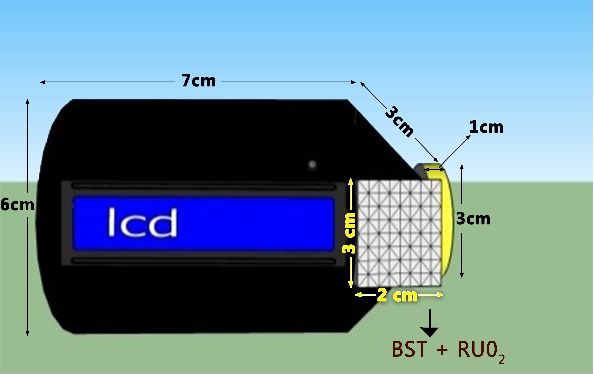
After Cleansing After 15 min after
   with Variations in          Cleansing                                                         and after
                                               (After Brushing            (after Brushing
      RuO2 Dope             (Straight out of                                                     Cleaning
                                                    Teeth)                  Teeth+Eat)
         (%)                      Bed)                                                             (mV)
                                                      (mV)                      (mV)
                                 (mV)
 Chemosensors02020, 8, 3          12.4                 12.7                      12.7                0.3 6 of 11
             2                    11.3                 12.5                      12.4                1.2
             4                    13.6                 17.9                      17.8                4.3
      Table 1. The voltage output measurement data of Ba0.5 Sr0.5 TiO3 film doped with RuO2 as a bad breath
             6                    12.9                 42.1                      41.9               29.2
        gas sensor with variations in the gas exposure distance: 2 cm, 4 cm, 6 cm and 8 cm.

     Table
    Ba0.5 Sr0.51 presents
               TiO        voltage
                  3 Film with     output
                               Output      measurement
                                       Voltage at Outputdata  with
                                                         Voltage at variations in halitosis
                                                                     Output Voltage at       gas Voltage
                                                                                         Output  exposureat
       Variations in RuO2        2 cm Exposure     4 cm Exposure       6 cm Exposure       8 cm Exposure
distance of Ba0.5Sr0.5TiO3 film with doped with varied RuO2 concentrations. Table 2 presents the output
             Dope (%)                (mV)              (mV)                (mV)                (mV)
voltage with a variety of oral conditions (halitosis-gas input) of the Ba0.5Sr0.5TiO3 film doped with
                    0                         12.5                     12.4                      12.4                     12.4
varied RuO2 concentrations.
                    2                         12.5                     12.5                      12.1                       -
     The measurements
                    4           in Table 116.9 aimed to evaluate 14.4   the film’s output voltage -        at distances of  - 2 cm, 4
cm, 6 cm, and6 8 cm. The response29.0           revealed whether27.7     or not the Ba0.5Sr0.5   26.4
                                                                                                  TiO3 film doped with    20.3 RuO2
gave a good response. The measurements presented in Table 2 were made by comparing the film’s
outputTable
          voltage 2. Voltage
                       based difference   measurement
                              on the film’s       responsedata  to of
                                                                   oralBa0.5 Sr0.5 TiO3 film
                                                                          conditions.     Thedoped      with RuO
                                                                                                 difference         2 in various
                                                                                                                 between      the oral
       oral output
condition     conditions.(∆V) was then used as proof that the film has a good sensitivity to halitosis gas. The
best sensitivity was demonstrated by Ba0.5SrFilm             0.5TiO  3 film
                                                                  Output      doped with 6% RuO2. This film was then
                                                                          Voltage
     Ba0.5 Sr0.5 TiO3 Film                                                                                            ∆V before and
applied
     withas     the Arduino
            Variations  in     Nano-based
                                 before Cleansingbad  breath
                                                           after Cleansing (after sensor.
                                                                 gas  detecting        after 15 min after (after      after Cleaning
       RuO2 Dope (%)                                                                                                       (mV)
     Table      2 indicates (Straight
                             that bad outbreath
                                          of Bed) (mV)    Brushing Teeth)
                                                   after cleaning     (after(mV)
                                                                              brushingBrushing
                                                                                           yourTeeth+Eat)
                                                                                                  teeth) and(mV)odor after      15 min
                0                      12.4                         12.7                         12.7
after brushing your teeth + eating produce output values that do not differ much. It suggests that the                       0.3
                2                      11.3                         12.5                         12.4                        1.2
condition read  4     by the Ba0.5Sr0.5TiO
                                       13.6 3 film doped with17.9     RuO2 6% is not the odor    17.8 from the toothpaste,   4.3   but
the bad breath  6                      12.9
                      from the bad breath                           42.1
                                                gas in the oral cavity.                          41.9                       29.2

                                Figure 8. (a) The Wheatstone circuit; (b) The op-amp circuit.

      Table 1 presents voltage output measurement data with variations in halitosis gas exposure
 distance of Ba0.5 Sr0.5 TiO3 film with doped with varied RuO2 concentrations. Table 2 presents the
 output voltage with a variety of oral conditions (halitosis-gas input) of the Ba0.5 Sr0.5 TiO3 film doped
 with varied RuO2 concentrations.
      The measurements in Table 1 aimed to evaluate the film’s output voltage at distances of 2 cm, 4 cm,
 6 cm, and 8 cm. The response revealed whether or not the Ba0.5 Sr0.5 TiO3 film doped with RuO2 gave a
 good response. The measurements presented in Table 2 were made by comparing the film’s output
 voltage based on the film’s response to oral conditions. The difference between the oral condition
 output (∆V) was then used as proof that the film has a good sensitivity to halitosis gas. The best
 sensitivity was demonstrated by Ba0.5 Sr0.5 TiO3 film doped with 6% RuO2 . This film was then applied
 as the Arduino Nano-based bad breath gas detecting sensor.
      Table 2 indicates that bad breath after cleaning (after brushing your teeth) and odor after 15 min
 after brushing your teeth + eating produce output values that do not differ much. It suggests that the
 condition read by the Ba0.5 Sr0.5 TiO3 film doped with RuO2 6% is not the odor from the toothpaste,
 but the bad breath from the bad breath gas in the oral cavity.
      Ba0.5 Sr0.5 TiO3 film doped with RuO2 had a resistance of approximately 106 Ω. By determining
 the values of R1 and R3 , the value of R2 could be obtained using the equation R1 ·R3 = R2 ·R4 .
      The steps to finding the value of R2 were: First, the value of R1 and R3 were determined to be 1 M
 and 100 Ω. Second, initially, R2 in the Wheatstone bridge circuit used a 100 K potentiometer which
 was done in order to make the V in potentiometer 0 volts. Then the potentiometer was disconnected
Chemosensors 2020, 8, 3 7 of 11
and the resistance in the potentiometer was measured using a multimeter. The value displayed by
the multimeter was the resistance value used as R2 . The resistance displayed was 4.68 K; therefore,
R2 = 4.7 K. The measurements were taken at the first and third terminals of the potentiometer.
The voltage signal emitted by the Wheatstone bridge was amplified by the op-amp circuit.
The microcontroller used was the ATMega168 (which is also known as the Arduino Nano) which had a
10-bit resolution and a reference voltage of 4.8 volts; therefore, the microcontroller could differentiate
between incoming voltages of 0.0046875 volts. To adjust the resolution of the Ba0.5 Sr0.5 TiO3 film doped
with RuO2 to the ADC resolution, an amplifying circuit (op-amp) was employed. The amplifying circuit
used in this study was a differential amplifying circuit and a non-inverting amplifying circuit, depicted
in Figure 8b. A differential amplifying circuit is a circuit that compares two inputs. The differential
amplifying circuit used was a combination between non-inverting and inverting circuits. The total
circuit amplification for the BST film was 2 times amplification from the differential amplifying circuit
and 11 times amplification from the non-inverting amplifying circuit, so the total amplification was
22 times. The mathematical calculations are represented by Equations (1) and (2).
Equation (1). The size of the amplification for the differential amplifying circuit was:
! !
Vout R Rf
= 1+ f , (1)
Vin Rin Rin
! !
Vout R R4
= 1+ 6 ,
Vin R5 R3
Vout 100K 100K
= 1+ ,
Vin 100K 100K
Vout
= 2 times.
Vin
Equation (2). The size of the amplification for the non-inverting amplifying circuit (amplifier 3) was:
!
Vout R
= 1+ f , (2)
Vin Rin
!
Vout R2
= 1+ ,
Vin R1
Vout 1M
= 1+ ,
Vin 100K
Vout
= 11 times.
Vin
The total amplification of the sensor’s circuit was 22 times.
3.2. The Atmega168/Arduino Nano Microcontroller Circuit
The controlling circuit in the bad breath detector prototype was a 10-bit ATMEGA168
microcontroller. The output voltage from the best film circuit was the input signal for the microcontroller.
The input for the microcontroller from the best film was PORTA.0. LCD assisted by the IIC
module; therefore, only two 2 PORTs: PORTA.4 for SDA and PORTA.5 for SCL. The digital PIN 3 was
used for the LED indicator.
3.3. Testing the Entire System
Halitosis is generally caused by bacteria that develop naturally in the mouth. These bacteria
produce sulfur-containing gases. As a result, during exhalation through the mouth, a pungent odor of
sulfurous gases is emitted. These gases are the focus of the detection capabilities of this device.form of the voltage on the first line of the LCD and the word “normal” on the second line. The results
of the bad breath, normal, and fragrant conditions are presented in Figure 9.
The MQ 136 sensor is a semiconductor component that functions as an odorant for tin oxide gas
(SnO2). The MQ 136 gas sensor has a high sensitivity to SO2. The MQ 136 can also be used to detect
other vapors
Chemosensors containing
2020, 8, 3 sulfur. Table 3 shows that the Ba0.5Sr0.5TiO3 film with 6% RuO2 doping 8 of 11
variation shows the average accuracy of the tool is ~99% measured against the MQ 136 sensor. This
proves that the Ba0.5Sr0.5TiO3 film testing with the 6% RuO2 doping variation shown in Figure 9
The operating principle of the device is that when the power source (5 volts) is activated,
provides an objective result when reading bad breath.
the power source provides the input voltage needed by every circuit used. When the Ba0.5 Sr0.5 TiO3
film Table
doped3. with RuO2 6%
Measurement
receives a stimulus in the form of bad breath, the ATMega168/Arduino
data of the accuracy of the voltage value between Ba0.5Sr0.5TiO3 film RuO2 6%
Nano microcontroller gives
doped relative to the commerciallya command to the LED and
manufactured LCD. (MQ 136) when detecting the odor
gas sensor
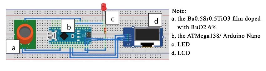
If the Ba
conditions0.5 Sr
of the TiO film
0.5oral cavity.
3 doped with RuO 2 6% receives a stimulus in the form of bad breath
(voltage output ≤ 12.9 mV), the microcontroller will command the LED to turn on (as an indicator of
bad breath) and the LCD will display the output values in the form Output Voltage
of the voltage on the first line and
the “bad breath” condition on the second line of the LCD. On the other hand, if theAfter
Before Cleansing After Cleansing 15 min after
Ba0.5 Sr 0.5 TiO3 film
(Straight out of (After Brushing (After Brushing
doped with RuO2 6% receives a stimulus in the form of “not bad breath” (voltage output > 42.1 mV),
Bed) Teeth) Teeth + Eat)
the microcontroller will give a command to the(mV) LED to remain turned (mV)off (as an indicator(mV) that the
mouth Bais not malodorous) and the LCD will display an output in the form of the voltage on the first
0.5Sr0.5TiO3 film with 6% doping
line of the LCD variations
and the word “fragrant” on the second 12.9 line. 42.1 41.9
GasIfsensor,
the Bamanufacturer’s
0.5 Sr0.5 TiO3 film doped
product (MQwith RuO2 6% receives a stimulus in the form of bad breath
12.7 42.4 42.2
(12.9 mV < voltage136) output ≤ 42.1 mV), the microcontroller will give a command to the LED to not turn
on (as an indicator ∆Vthat
(mV)the mouth is in a normal condition)
0.2 and the LCD 0.3 will display an output
0.3 in the
Accuracy (%) 98.4 99.3
form of the voltage on the first line of the LCD and the word “normal” on the second line. The results 99.3
of the bad breath, normal, and fragrant conditions are presented in Figure 9.
Chemosensors 2020, 8, x FOR PEER REVIEW 9 of 11
(a) (b)
(c)
Figure9.9.(a)(a)The
Figure Theresults
resultsofofthe
thetesting
testingatataa“Bad
“Badbreath”
breath”oral
oralcondition;
condition; (b)
(b) the
the results
results of the testing at a
a“Normal”
“Normal”oral oralcondition;
condition;(c) (c)The
Theresults
resultsofofthe
thetesting
testingatataa“Fragrant”
“Fragrant”oral
oralcondition.
condition.
Thetool
This MQis136 sensor
made is a semiconductor
to facilitate user detectioncomponent that functions
of bad breath, as an odorant
so this portable unit canforbetin oxide
carried
gas (SnO
everywhere ). The MQ 136 gas sensor has a high sensitivity
2 by the user. The dimensions of the tool are shown in Figure to SO 2 . The MQ 136 can also be
6. The position of the sensorused
isto detect
right other
inside thevapors containing
packaging containersulfur.
such Table 3 shows that
as a microphone. the Ba
Users Sr0.5the
can0.5use TiO 3 film
tool by: with 6% RuO2
(1) activating
the switch to the ‘on’ position; (2) the user blows the microphone in which there is a mouth sensor.
doping variation shows the average accuracy of the tool is ~99% measured against the MQ 136 odor
This proves
sensor. Input that the
in the Ba0.5ofSrbad
form 0.5 TiO3 film
breath testing
will with
be read theprocessed
and 6% RuO2 by doping variation shownThe
the microcontroller. in Figure
results 9
ofprovides an objectiveprocessing
the microcontroller result when reading
will bad breath.
be displayed on the 16 × 2 LCD as shown in Figure 9.
Figures 6a and 9 show that this device is built to provide user safety from electricity. Besides
using only DC power supplies, the electronic components are housed inside a packaging container
made of an insulating type material, ensuring user safety from electricity. The RuO2 doped
Ba0.5Sr0.5TiO3 film cover container is also shock-resistant from saliva and toxins. If the mouth or saliva
touches the RuO2 doped Ba0.5Sr0.5TiO3 film cover container it will not provide any electrical response
because the container is coated with an insulating material, making it very safe.
Halitosis is a medical term for bad breath. Halitosis is a very common condition. According to
the American Dental Association, at least 50 percent of adults around the world have bad breath. So
generally, many do not realize that they have this condition.
One recent innovation for oral hygiene has been presented before. the innovation was called
Breathometer Mint. The tool is used to monitor the user’s mouth odor. With this tool, the user can
find out whether the condition of the oral cavity is in good or bad condition. This device is integratedChemosensors 2020, 8, 3 9 of 11
Table 3. Measurement data of the accuracy of the voltage value between Ba0.5 Sr0.5 TiO3 film RuO2
6% doped relative to the commercially manufactured gas sensor (MQ 136) when detecting the odor
conditions of the oral cavity.
Output Voltage
before Cleansing after Cleansing (after after 15 min after (after
(Straight out of Bed) Brushing Teeth) Brushing Teeth + Eat)
(mV) (mV) (mV)
Ba0.5 Sr0.5 TiO3 film with 6% doping
12.9 42.1 41.9
variations
Gas sensor, manufacturer’s product
12.7 42.4 42.2
(MQ 136)
∆V (mV) 0.2 0.3 0.3
Accuracy (%) 98.4 99.3 99.3
This tool is made to facilitate user detection of bad breath, so this portable unit can be carried
everywhere by the user. The dimensions of the tool are shown in Figure 6. The position of the sensor is
right inside the packaging container such as a microphone. Users can use the tool by: (1) activating the
switch to the ‘on’ position; (2) the user blows the microphone in which there is a mouth odor sensor.
Input in the form of bad breath will be read and processed by the microcontroller. The results of the
microcontroller processing will be displayed on the 16 × 2 LCD as shown in Figure 9.
Figures 6a and 9 show that this device is built to provide user safety from electricity. Besides using
only DC power supplies, the electronic components are housed inside a packaging container made
of an insulating type material, ensuring user safety from electricity. The RuO2 doped Ba0.5 Sr0.5 TiO3
film cover container is also shock-resistant from saliva and toxins. If the mouth or saliva touches the
RuO2 doped Ba0.5 Sr0.5 TiO3 film cover container it will not provide any electrical response because the
container is coated with an insulating material, making it very safe.
Halitosis is a medical term for bad breath. Halitosis is a very common condition. According
to the American Dental Association, at least 50 percent of adults around the world have bad breath.
So generally, many do not realize that they have this condition.
One recent innovation for oral hygiene has been presented before. the innovation was called
Breathometer Mint. The tool is used to monitor the user’s mouth odor. With this tool, the user can
find out whether the condition of the oral cavity is in good or bad condition. This device is integrated
with applications on smartphones that will provide information about the user’s oral cavity. Its use
is quite practical, the tool is simply inserted into the mouth, then the user can exhale through his or
her mouth. Then the Breathometer will detect the level of bacteria in the mouth. If the number of
bacteria in the oral cavity is high, an unpleasant odor may result [39]. Unfortunately, the tool can only
be used to monitor the number of bacteria in the mouth, a proxy for bad breath, but it cannot detect the
distinctive odor of the types of gas that makes the mouth smell. This is the background rationale for
the making a Ba0.5 Sr0.5 TiO3 film application which is doped with RuO2 6% as an Arduino Nano-based
odor detection sensor. This tool can monitor bad breath directly by detecting the concentration of
sulfurous gases released.
4. Conclusions
The Ba0.5 Sr0.5 TiO3 film doped with RuO2 can be used as a bad-breath detecting sensor because
it demonstrated a response in the form of voltage changes when exposed to changes in the aroma.
The test results demonstrated that Ba0.5 Sr0.5 TiO3 film doped with RuO2 with a dope concentration
of 6% was the best film of those tested. This film was then applied as the Arduino Nano-based
bad-breath detecting sensor. The function of this film is to read bad breath from the types of gas
released (sulfur-containing gases produced by naturally occurring bacteria that inhabit the mouth).
The use of this tool is very practical, achieved simply by turning on the power on the tool, then blowing
over the container shaped like a microphone. The results of bad breath will be displayed on theChemosensors 2020, 8, 3 10 of 11
16 × 2 LCD. A device housing made of insulating material provides an important safety role for
the user.
Author Contributions: Researchers came from the four best universities in Indonesia. In this study, researchers
have contributed by following their respective fields. I., B.Y. and F. contributed to the fields of physics and thin
film. R.S. contributed in the fields of electronics, hardware and programming. M.Z.F. contributed to the field of
chemistry. All authors have read and agreed to the published version of the manuscript.
Funding: This research was funded by USAID through the SHERA program-Centre for Development of Sustainable
Regions (CDSR) and Program Penelitian Dasar Unggulan Perguruan Tinggi (PDUPT) DRPM, Republic of Indonesia
with grant number 3/E1/KP.PTNBH/2019.
Conflicts of Interest: The authors declare no conflict of interest.
References
1. Herawati, D. Mengenali halitosis patologis berdasarkan lokasi asal untuk keberhasilan perawatan Mal-odor
Oral. Majalah Ceramah Ilmiah FKG UGM Yogyakarta 2003, 3, 118–121.
2. Djaya, A. Halitosis: Nafas Tak Sedap, 1st ed.; Dental Lintas Mediatama: Jakarta, Indonesia, 2000; pp. 2–35.
3. McDowell, K.; Denise, K. Halitosis holistik. Maj. Kedokt. Gigi Dent. Horis. 2002, 3, 30–37.
4. Darwis, E.W. Jangan biarkan nafas bau menghambat pergaulan. J. PDGI 1997, 25, 12–14.
5. Preti, G.; Lawley, H.J.; Hormann, C.A.; Cowart, B.J.; Feldman, R.S.; Lowry, L.D.; Young, I.M. Non-Oral
and oral aspect of oral malodor. In Bad Breath Research Perspectives, 2nd ed.; Rosenberg, M., Ed.; Ramot
Publishing-Tel Aviv University: Tel Aviv, Israel, 1997; pp. 149–150.
6. Richie, E.; Nani, D.; Pasole, D.; Muhammad, D.; Ade, K.; Johan, I.; Hendradi, H. ‘The optical band gap of
LiTaO3 and Nb2O5—Doped LiTaO3 thin films based on Tauc Plot method to be applied on satellite’. IOP
Conf. Ser. Earth Environ. Sci. 2017, 54, 012092–012099.
7. Irzaman, Y.; Darvina, A.; Fuad, P.; Arifin, M.; Budiman, M.; Barmawi, M. Physical and pyroelectric
properties of tantalum oxide doped lead zirconium titanate [Pb0.9950 (Zr0.525 Ti0.465 Ta0.010 )O3 ] thin films and
its application for IR sensor. Phys. Status Solidi (a) Ger. 2003, 199, 416–424. [CrossRef]
8. Syafutra, H.; Irzaman, H.; Subrata, I.D.M. Integrated visible light sensor based on thin film ferroelectric
material BST to microcontroller ATMega8535. Mater. Sci. Technol. 2010, 1, 291–296.
9. Irzaman; Pebriyanto, Y.; Apipah, E.R.; Noor, I.; Alkadri, A. Characterization of Optical and Structural of
Lanthanum Doped LiTaO3 Thin Films. Integr. Ferroelectr. 2015, 167, 137–145. [CrossRef]
10. Mulyadi, R.; Wahyuni, H. Barium strontium titanate thin film growth with variation of lanthanum dopant
compatibility as sensor prototype in the satellite technology. IOP Conf. Ser. Earth Environ. Sci. 2018, 149,
012069–012076. [CrossRef]
11. Irzaman Syafutra, H.; Rancasa, E.; Nuayi, A.W.; Rahman, T.G.N.; Nuzulia, N.A.; Supu, I.; Sugianto
Tumimomor, F.; Surianty Muzikarno, O. The effect of Ba/Sr ratio on electrical and optical properties of
BaxSr(1-x)TiO3(x = 0.25; 0.35; 0.45; 0.55) thin film semiconductor. J. Ferroelectr. 2013, 445, 4–17. [CrossRef]
12. Choi, E.S.; Lee, J.C.; Hwang, J.S.; Yoon, S.G. Electrical characteristics of the contour vibration mode
piezoelectric transformer with ring/dot electrode area ratio. J. Appl. Phys. 1993, 38, 5317. [CrossRef]
13. Momose, S.; Nakamura, T.; Tachibana, K. Effects of gas phase thermal decompositions of chemical vapor
deposition source molecules on the deposition of BST films. J. Appl. Phys. 2000, 39, 5384. [CrossRef]
14. Gao, Y.; He, S.; Alluri, P.; Engelhard, M.; Lea, A.; Finder, S.; Melnick, J.; Hance, B. Effect of precursors and
substrate materials on microstructure, dielectric properties and step coverage of (Ba, Sr)TiO3 films grown by
metalorganic chemical vapor deposition. J. Appl. Phys. 2000, 87, 124–132. [CrossRef]
15. Auciello, O.; Scott, J.F.; Ramesh, R. The physics of ferroelectric memories. Phys. Today 1998, 51, 22–27.
[CrossRef]
16. Verma, K.; Sharma, S.; Sharma, D.K.; Kumar, R.; Rai, R. Sol-gel processing and characterization of
nanometer-sized (Ba,Sr)TiO3 ceramics. Adv. Mater. Lett. 2012, 3, 44–49. [CrossRef]
17. Giridharan, N.V.; Jayavel, R.; Ramasamy, P. Structural, morphological and electrical studies on barium
strontium titanate thin films prepared by sol-gel technique. Crystal Res. Technol. 2001, 36, 65–72. [CrossRef]
18. Chen, X.; Cai, W.; Fu, C.; Chen, H.; Zhang, Q. Synthesis and morphology of Ba(Zr0,20 Ti0,80 )O3 powder
obtained by sol-gel methode. J. Sol-Gel Sci. Technol. 2011, 57, 149–156. [CrossRef]Chemosensors 2020, 8, 3 11 of 11
19. Wang, F.; Uusimaki, A.; Leppavuori, S.; Karmanenko, S.F.; Dedyk, A.I.; Sakharov, V.I.; Serenkov, I.T. BST
ferroelectric film prepared with sol-gel process and its dielectric performance in planar capacitor structure.
J. Mater. 1998, 13, 1243.
20. Tyunina, M. Dielectric properties of atomic layer deposited thin film barium strontium titanate.
Integr. Ferroelectr. 2008, 102, 29–36. [CrossRef]
21. Kim, S.; Kang, T.S.; Je, J.H. Structural characterization of laser ablation epitaxial BST thin films on MgO (001)
by synchrotron x-ray scattering. J. Mater. 1999, 14, 2905–2911.
22. Zhu, X.H.; Zheng, D.N.; Peng, J.L.; Chen, Y.F. Enhanced dielectric properties of Mn-doped Ba0,6 Sr0,4 TiO3
thin films fabricated by pulsed laser deposition. Mater. Lett. 2005, 60, 1224–1228. [CrossRef]
23. Izuha, M.; Ade, K.; Koike, M.; Takeno, S.; Fukushima, N. Electrical properties and microstructure of
Pt/BST/SrRuO3 capacitors. J. Appl. Phys. 1997, 70, 1405.
24. Lee, J.S.; Park, J.S.; Kim, J.S.; Lee, J.H.; Lee, Y.H.; Hahn, S.R. Preparation of BST thin films with high
pyroelectric coefficients in ambient temperatures. J. Appl. Phys. 1999, 38, L574. [CrossRef]
25. Irzaman, H.; Darmasetiawan, H.; Hardhienata, H.; Erviansyah, R.; Maddu, A.; Hikam, M.; Arifin, P. Electrical
properties of photodiode BST thin film doped with ferrium oxide using chemical deposition solution method.
J. Atom Indones. 2010, 6, 57–62.
26. Irzaman, H.; Syafutra, H.; Darmasetiawan, H.; Hardhienata, H.; Erviansyah, R.; Huriawati, F.; Maddu, A.;
Arifin, P. Electrical properties of photodiode Ba0.25 Sr0.75 TiO3 (BST) thin film doped with ferric oxide on
p-type Si (100) substrate using chemical solution deposition method. J. Atom Indones. 2011, 37, 133–138.
[CrossRef]
27. Baumert, B.A.; Chang, L.H.; Matsuda, A.T.; Tracy, C.J. A study of BST thin films for use in bypass capacitors.
J. Mater. 1998, 13, 197.
28. Itskovsky, M.A. Kinetics of ferroelectric phase transition: Nonlinear pyroelectric effect and ferroelectric solar
cell. J. Appl. Phys. 1999, 38, 4812. [CrossRef]
29. Darmasetiawan, H.; Irzaman, H.; Indro, M.N.; Sukaryo, S.G.; Hikam, M.; Bo, N.P. Optical properties of
crystalline Ta2 O5 thin films. Phys. Status Solidi (a) 2002, 193, 53–60. [CrossRef]
30. Irzaman, A.; Nuraisah, A.; Aminullah; Hamam, K.A.; Alatas, H. Optical properties and crystal structure of
lithium doped Ba0.55Sr0.45TiO3 (BLST) thin films. Ferroelectr. Lett. Sect. 2018, 45, 14–21. [CrossRef]
31. Dahrul, M.; Syafutra, H.; Arif, A.; Irzaman, H.; Indro, M.N.; Siswadi. Synthesis and characterizations
photodiode thin film barium strontium titanate (BST) doped niobium and iron as light sensor. In Proceedings
of the The 4th Asian Physics Symposium, American Institute of Physics (AIP) Conference, West Java,
Indonesia, 12–13 October 2010; Volume 1325, pp. 43–46.
32. Irzaman Dahrul, M.; Yuliarto, B.; Hammam, K.A.; Alatas, H. Effects of Li and Cu dopants on the crystal
structure of Ba0.65Sr0.35TiO3 thin films. Ferroelectr. Lett. Sect. 2018, 45, 49–57. [CrossRef]
33. Irzaman; Sitompul, H.; Masitoh; Misbakhusshudur, M. Optical and structural properties of lanthanum
doped lithium niobate thin films. Ferroelectrics 2016, 502, 9–18. [CrossRef]
34. Nuayi, A.W.; Alatas, H.; Irzaman, H.; Rahmat, M. Enhancement of Photon Absorption on BaxSr(1-x)TiO3
Thin-Film Semiconductor Using Photonic Crystal. Int. J. Opt. 2014, 2014, 534145. [CrossRef]
35. Hamdani, A.; Komaro, M. A Synthesis of Bax Sr1-X TiO3 Film and Characterization Of Ferroelectric Properties
and Its Extension as Random Access Memory. Mater. Phys. Mech. 2019, 42, 131–140.
36. Schwartz, R.W. Chemical solution deposition of perovskite thin film. J. Chem. Mater. 1997, 9, 2325–2340.
[CrossRef]
37. Endah, K.P.; Rofiqul, U.; Bibin, B.A.; Hidetoshi, S.; Brian, Y.; Husin, A. Micro-Raman analysis of Ba0.2 Sr0.8 TiO3
(barium strontium titanate) doped of chlorophyll of cassava leaf. Ferroelectrics 2019, 540, 227–237.
38. Irzaman; Siskandar, R.; Aminullah; Irmansyah; Alatas, H. Characterization of Ba0.55 Sr0.45 TiO3 films as light
and temperature sensors and its implementation on automatic drying system model. J. Integr. Ferroelectr.
2016, 168, 130–150. [CrossRef]
39. Peverall, R.; Hancock, G. GAD Ritchie. Portable Breath Volatile Organic Compounds Analyser and
Corresponding Unit. U.S. Patent 2016/0150995 A1.
© 2019 by the authors. Licensee MDPI, Basel, Switzerland. This article is an open access
article distributed under the terms and conditions of the Creative Commons Attribution
(CC BY) license (http://creativecommons.org/licenses/by/4.0/).You can also read