AS6500 Datasheet - 4-Channel Time-to-Digital Converter - ScioSense

Page created by Terrance Byrd
 
CONTINUE READING
AS6500 Datasheet - 4-Channel Time-to-Digital Converter - ScioSense
Datasheet
DS000640

AS6500
4-Channel Time-to-Digital Converter

v4-00 • 2020-Feb-28

This product was initally sold under ams AG is now owned by ScioSense B.V. .
Only the ownership has changed. The specification and properties of the product remain unchanged.
AS6500
                                                                                                                                   Content Guide

Content Guide

1         General Description ...................... 3                        8.1   Time Measurements and Results ............... 28
                                                                              8.2   Resolution ................................................... 30
1.1       Key Benefits & Features ............................... 3           8.3   Combining Two Stop Channels .................. 31
1.2       Applications .................................................. 4   8.4   Input Pins for Time Measurement .............. 33
1.3       Block Diagram .............................................. 4      8.5   SPI Communication Interface ..................... 35
2         Ordering Information .................... 5                         8.6   Coding of Results ....................................... 38
                                                                              8.7   Conversion Latency and Conversion Rate . 40
3         Pin Assignment ............................. 6                      8.8   Conversion Rate ......................................... 41
3.1       Pin Diagram .................................................. 6    9     Application Information............... 45
3.2       Pin Description ............................................. 6
                                                                              9.1   Configuration Examples ............................. 45
4         Absolute Maximum Ratings ......... 9                                9.2   Example C++ Code .................................... 45
                                                                              9.3   Schematic ................................................... 48
5         Recommended Operation                                               9.4   External Components ................................. 49
          Conditions.....................................10
                                                                              10    Package Drawings & Markings ... 51
6         Typical Characteristics ................11
                                                                              11    Reel Information .......................... 53
6.1       Converter Characteristics ........................... 11
6.2       Power Supply Characteristics .................... 12                12    Soldering & Storage Information 54
6.3       Reference Clock and Stop Input
          Requirements ............................................. 13
6.4       Serial Communication Interface ................. 14
6.5       Typical Operating Characteristics .............. 16
7         Register Description ....................19
7.1       Register Overview ...................................... 19
7.2       Detailed Register Description ..................... 21
8         Detailed Description.....................28

Datasheet • PUBLIC
DS000640 • v4-00 • 2020-Feb-28 • 2020-Feb-28                                                                                                 54 │ 2
AS6500
                                                                                                    General Description

1              General Description
               The AS6500 is a high performance time-to-digital converter (TDC) frontend device. It is a derivative of
               TDC-GPX2, with CMOS inputs and serial SPI output only. It comes in a QFN40 package. AS6500
               achieves high measurement performance and high data throughput. High configuration flexibility and
               unlimited measurement range cover many applications, ranging from portable handheld laser range
               equipment to ambitious time-of-flight measurements of high performance.

               AS6500 calculates calibrated stop measurements, referenced to the applied reference clock.
               Combinations of single shot accuracy of 10ps with lowest pulse-to-pulse spacing
AS6500
                                                                                                                                                              General Description

1.2            Applications
               ●      Laser range measurement
               ●      Time-of-flight measurement
               ●      Lidar

1.3            Block Diagram
               The functional blocks of this device are shown below:

               Figure 2:
               Functional Blocks of AS6500

                                                                                     CVDD18

                                                                                              DVDD18

                                                                                                                                                     DVDD33
                                           TVDD33

                                                              TVDD18

                                                                                                                    DVDD18

                                                                                                                                    RVDD33
                                 DISABLE
                                                                                                                              AS6500

                                  STOP1
                                                                                   TDC
                                                                                              FIFO

                                  STOP3
                                                                                   TDC
                                                                                              FIFO

                                                                                                                                                              CVDD18O
                                                                                                                                                    LVR       TVDD18O
                                  STOP2
                                                                                   TDC                                                                        DVDD18O
                                                                                              FIFO

                                  STOP4
                                                                                   TDC
                                                                                              FIFO

                                 RSTIDX                                          Reference
                                                                                   Clock
                                                                                   Index
                                                                                  Counter

                                                                                                       Encoder                     Configuration
                                 REFCLK
                                                                                   TDC                              Serial Interface
                                                                                                        INTERRUPT

                                                                                                                             SCK

                                                                                                                                             MISO
                                                                                                                      SSN

                                                                                                                                    MOSI
                                                                       REFOSCO
                                                    REFOSCI

Datasheet • PUBLIC
DS000640 • v4-00 • 2020-Feb-28                                                                                                                                             54 │ 4
AS6500
                                                                         Ordering Information

2              Ordering Information

                Ordering Code    Package   Marking   Delivery Form   Delivery Quantity

                                           AS6500
                AS6500-FQFM      QFN40               T&R             500 pcs/reel
                                           -FQF

Datasheet • PUBLIC
DS000640 • v4-00 • 2020-Feb-28                                                         54 │ 5
AS6500
                                                                                                                                                        Pin Assignment

3              Pin Assignment

3.1            Pin Diagram
               Figure 3:
               AS6500 QFN40

                                                                                                     INTERRUPT
                                                                                                                 REFOSCO
                                                                                                                           REFOSCI
                                                 DVDD33

                                                                                                                                     TVDD18
                                                          DGND
                                                                   MISO
                                                                            MOSI
                                                                                     SCK
                                                                                              SSN
                                                 40

                                                                                                                                     31
                                                                                                                                       30
                                                                                                                                              TGND
                                        NC
                                             1

                                                                                                                                              STOP1
                                  DVDD33
                                                                                                                                              STOP2
                                        NC
                                                                                                                                              TVDD33
                                      TSTO
                                                                                                                                              RSTIDX
                                      TSTO
                                                                             AS6500                                                           REFCLK
                                      TSTO
                                                                                                                                              DISABLE
                                      TSTO
                                                                                                                                              TGND
                                        NC
                                                                                                                                              STOP3
                                      TSTO
                                                                                                                                              STOP4
                                                                                                                                     21
                                             10

                                        NC
                                              11

                                                                                                                                      20
                                                 DGND
                                                          DVDD33
                                                                   DVDD18
                                                                            RVDD33
                                                                                     VDD18O
                                                                                              RGND
                                                                                                     CGND
                                                                                                                 CVDD18
                                                                                                                           TVDD18
                                                                                                                                     TVDD33

3.2            Pin Description
               Figure 4:
               Pin Description of AS6500 QFN40

                Pin                                                                                                                                         Not
                             Pin Name        Pin Type                                 Description
                Number                                                                                                                                      Used

                1            NC                                                       Not connected
                2            DVDD33          Power Supply                             3.3V supply for digital and IO units
                3            NC                                                       Not connected

Datasheet • PUBLIC
DS000640 • v4-00 • 2020-Feb-28                                                                                                                                  54 │ 6
AS6500
                                                                                                      Pin Assignment

                Pin                                                                                       Not
                             Pin Name    Pin Type       Description
                Number                                                                                    Used

                4            TSTO                       Test pin
                5            TSTO                       Test pin
                6            TSTO                       Test pin
                7            TSTO                       Test pin
                8            NC                         Not Connected
                9            TSTO                       Test pin
                10           NC                         Not Connected
                11           DGND        Power Supply   Ground for digital and IO units
                12           DVDD33      Power Supply   3.3V supply for digital and IO units
                13           DVDD18      Power Supply   1.8V supply for digital and IO units
                14           RVDD33      Power Supply   3.3V supply for linear voltage regulator
                                         Regulator      1.8V supply for digital and IO units, regulator
                15           VDD18O
                                         Output         output
                16           RGND        Power Supply   Ground for linear voltage regulator
                17           CGND        Power Supply   Ground for TDC
                18           CVDD18      Power Supply   1.8V positive supply for TDC
                19           TVDD18      Power Supply   1.8V positive supply for time front-end
                20           TVDD33      Power Supply   3.3V positive supply for time front-end
                21           STOP4       CMOS Input     Positive stop input for channel 4
                22           STOP3       CMOS Input     Positive stop input for channel 3
                23           TGND        Power Supply   Ground for 1.8V time front-end supply
                24           DISABLE     CMOS Input     Positive disabling pin for stop channels          TVDD33
                25           REFCLK      CMOS Input     Negative clock signal of reference clock          TVDD33
                26           RSTIDX      CMOS Input     Positive reference index reset signal             TVDD33
                27           TVDD33      Power Supply   3.3V positive supply for time front-end
                28           STOP2       CMOS Input     Positive stop input for channel 2
                29           STOP1       CMOS Input     Positive stop input for channel 1
                30           TGND        Power Supply   Ground for TDC
                31           TVDD18      Power Supply   1.8V positive supply for time front-end           Open
                                         XOSC Driver
                32           REFOSCI                    Input for quartz as reference clock               Open
                                         In
                                         XOSC Driver
                33           REFOSCI                    Output for quartz as reference clock              Open
                                         Out
                34           INTERRUPT   CMOS output    SPI interrupt                                     Open
                35           SSN         LVTTL Input    SPI slave select not + interface reset

Datasheet • PUBLIC
DS000640 • v4-00 • 2020-Feb-28                                                                                54 │ 7
AS6500
                                                                                               Pin Assignment

                Pin                                                                                Not
                             Pin Name   Pin Type       Description
                Number                                                                             Used

                36           SCK        LVTTL Input    SPI serial clock
                37           MOSI       LVTTL Input    SPI serial data master out , slave In
                                        LVTTL
                38           MISO                      SPI serial data master in, slave Out
                                        Tristate
                39           DGND       Power Supply   Ground for digital and IO units
                40           DVDD33     Power Supply   3.3V supply for digital and IO units        DVDD33

Datasheet • PUBLIC
DS000640 • v4-00 • 2020-Feb-28                                                                         54 │ 8
AS6500
                                                                                                                  Absolute Maximum Ratings

4              Absolute Maximum Ratings
               Stresses beyond those listed under “Absolute Maximum Ratings“ may cause permanent damage to
               the device. These are stress ratings only. Functional operation of the device at these or any other
               conditions beyond those indicated under “Operating Conditions” is not implied. Exposure to absolute
               maximum rating conditions for extended periods may affect device reliability.

               Figure 5:
               Absolute Maximum Ratings of AS6500

                Symbol                 Parameter                              Min             Max      Unit       Comments
                Electrical Parameters
                VDD33                  3.3V Supply Voltage to Ground          -0.5            4.0      V          Pin: DVDD33, TVDD33,
                                                                                                                  RVDD33
                VDD18                  1.8V Supply Voltage to Ground          -0.5            2.2      V          Pin: DVDD18, TVDD18,
                                                                                                                  CVDD18
                                       Voltage between ground pins            -0.3            +0.3     V          Pin: DGND, TGND, RGND
                Vosc                   Voltage at input of oscillator         -0.3         VDD18 +     V          Pin: REFOSCIN
                                       cell                                                  0.3
                Electrostatic Discharge
                ESDHBM                 Electrostatic Discharge HBM                   ± 1000            V          JS-001-2014
                Temperature Ranges and Storage Conditions
                                       Operating Junction
                TJ                                                            -40             125      °C
                                       Temperature
                TSTRG                  Storage Temperature Range              - 65            150      °C
                TBODY                  Package Body Temperature                               260      °C         IPC/JEDEC J-STD-020 (1)
                                       Relative Humidity (non-
                RHNC                                                           5              85       %
                                       condensing)
                                                                                                                  Maximum floor life time of
                MSL                    Moisture Sensitivity Level                      3
                                                                                                                  168h

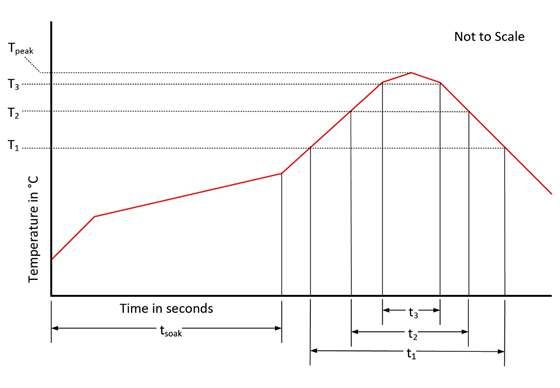
               (1)      The reflow peak soldering temperature (body temperature) is specified according to IPC/JEDEC J-STD-020
                        “Moisture/Reflow Sensitivity Classification for Nonhermetic Solid State Surface Mount Devices.” The lead finish for
                        Pb-free leaded packages is “Matte Tin” (100 % Sn)

Datasheet • PUBLIC
DS000640 • v4-00 • 2020-Feb-28                                                                                                            54 │ 9
AS6500
                                                                                                   Recommended Operation Conditions

5              Recommended Operation Conditions
               Recommended operating ratings indicate conditions for which the device is functional, but do not
               guarantee specific performance limits. Test conditions for guaranteed specification are expressly
               denoted.

               Figure 6:
               Recommended Operation Conditions of AS6500

                Symbol            Pin                      Description                           Min         Typ         Max        Unit

                Power-Supply
                                  DVDD33,
                VDD33             TVDD33,                  Supply Voltage                        2.4         3.3         3.6        V
                                  RVDD33
                                  DVDD18,                  Core Supply Voltage
                VDD18             TVDD18,                  powered by integrated                 1.7         1.8         1.9        V
                                  CVDD18                   regulator, pin VDD18O
                Temperature
                                                           Operating free air
                TA                                                                               -40                     125        °C
                                                           temperature(1)
                Reference & Stop Inputs
                VIL,CMOS          STOP1, STOP2,            CMOS Input Low Voltage                                        0.4        V
                                  STOP3, STOP4,
                VIH,CMOS          REFCLK,                                                        VDD33
                                  RSTIDX,                  CMOS Input High Voltage                                                  V
                                                                                                 – 0.4
                                  DISBALE
                SPI-Interface
                VIL                                        Digital Input LOW Voltage                                     0.8        V
                                  SCK, MOSI, SSN                                                 0.7 ×
                VIH                                        Digital Input HIGH Voltage                                               V
                                                                                                 VDD33
                                  INTERRUPT,               Load Capacitance to
                CLOAD                                                                                                    20         pF
                                  MISO                     Ground

               (1)    Recommended Operating Ratings indicate conditions for which the device is functional, but do not guarantee specific
                      performance limits. Test conditions for guaranteed specification are explicitly denoted.

Datasheet • PUBLIC
DS000640 • v4-00 • 2020-Feb-28                                                                                                      54 │ 10
AS6500
                                                                                                     Typical Characteristics

6              Typical Characteristics
               The following test levels apply to all following characteristics:

               Figure 7:
               Test Levels

                Test Level             Description

                I                      100% production tested.
                II                     100% production tested at 25°C and guaranteed by design and
                                       characterization testing
                III                    Parameter is guaranteed by design and characterization testing
                IV                     Sample tested
                V                      Parameter is a typical value only.

6.1            Converter Characteristics
               General Conditions: VDD33 = 3.3 V; VDD18 = 1.8 V; TA = 0 °C to 80 °C.

               Figure 8:
               Converter Characteristics

                Symbol       Description               Condition                    TL    Min   Typ       Max      Unit

                Accuracy of Time Measurement
                     RMS     Single-shot RMS           High_Resolution = 0 (off)                20        30
                             resolution                High_Resolution = 1 (2x)     IV          15        20       ps
                                                       High_Resolution = 2 (4x)                 10        15
                INL          Integral non-linearity                                 IV                    20       ps
                DNL          Differential non-
                                                                                    V           5                  ps
                             linearity
                             No missing code           At time quantization level   III   Assured
                             Channel to channel
                                                       At same times measured       IV          20        100      ps
                             isolation
                             Offset error              High_Resolution = 0 (off)                100
                                                       High_Resolution = 1 (2x)     V           150                ps
                                                       High_Resolution = 2 (4x)                 200

Datasheet • PUBLIC
DS000640 • v4-00 • 2020-Feb-28                                                                                      54 │ 11
AS6500
                                                                                                         Typical Characteristics

                Symbol        Description              Condition                   TL          Min     Typ     Max       Unit

                              Offset error             High_Resolution = 0 (off)                       0.5     3
                              temperature drift        High_Resolution = 1 (2x)    IV                  1                 ps/K
                                                       High_Resolution = 2 (4x)                        1.5
                Switching Performance
                tCONV         Converter latency        High_Resolution = 0 (off)                               20
                                                       High_Resolution = 1 (2x)    III                         50        ns
                                                       High_Resolution = 2 (4x)                                100
                              Peak conversion rate     High_Resolution = 0 (off)                               50
                                                       High_Resolution = 1 (2x)    III                         20        MSPS
                                                       High_Resolution = 2 (4x)                                10
                              Maximal read-out rate    SCK = 50MHz
                              SPI :                    Opcode + 48-Bit             III         0.9                       MSPS
                              Opcode + 16 Bit          Opcode + 16-Bit                                         2.1

6.2            Power Supply Characteristics
               General Conditions: VDD33 = 3.3 V; VDD18 = 1.8 V; TA = 0 °C to 80 °C.

               Figure 9:
               Power Supply Characteristics

                Symbol            Description           Condition                        TL      Min     Typ       Max    Unit

                Supply Voltage
                    tVDD18O       Delay from power-
                                  up of RVDD33 to
                                                        Cload = 100 µF                   V                         100    ms
                                  TVDD18, CVDD18,
                                  DVDD18 stable
                   PTOT,MIN       Minimum total         CMOS inputs and SPI
                                  power dissipation     read
                                                                                         V               60               mW
                                                        fREFCLK = 5 MHz
                                                        conversion rate 1MSPS
                Detailed Current Consumption
                IDVDD18,REFCLK    Core current into
                                                        fREFCLK = 5 MHz                  V               2                mA
                                  REFCLK
                 IDVDD18,STOP     Current per stop
                                                        Stop rate = 0.5 MHz              V               0.5              mA
                                  channel
                    ICVDD18       Current with
                                                                                         V               14               mA
                                  activated TDC core
                ITVDD18,REFOSC    Quartz oscillator
                                                        fREFOSC = 4 MHz                  III             2                mA
                                  current if used

Datasheet • PUBLIC
DS000640 • v4-00 • 2020-Feb-28                                                                                           54 │ 12
AS6500
                                                                                                            Typical Characteristics

                Symbol            Description            Condition                      TL       Min       Typ      Max     Unit

                       IDDQ       Quiescent current
                                                                                        II                 60       100     µA
                                  mainly by IRVDD33
                       ILKG       Input leakage
                                                         CMOS, Digital                  II       -10                1       µA
                                  current

6.3            Reference Clock and Stop Input Requirements
               General Conditions: VDD33 = 3.3 V; VDD18 = 1.8 V; TA = 0 °C to 80 °C; VID = 200mV; VIC = 1.25 V;
               VIL = 0 V; VIH = 3.3 V

               Figure 10:
               Clock and Input Characteristics

                Symbol        Description             Condition                   TL         Min       Typ       Max      Unit

                fREFCLK       Reference clock         High_Resolution = 0 (off)              2         5         12.5
                              frequency               High_Resolution = 1 (2x)    III        2         5         12.5     MHz
                                                      High_Resolution = 2 (4x)               2         5         10.0
                TREFCLK       Reference clock                                     III        83        200       500      ns
                              period
                              Reference clock
                                                                                  V                              100      ps
                              jitter
                              Reference clock
                                                      No requirement
                              stability
                tPWH,STOP     Minimum pulse
                                                      CMOS                        III        5         10                 ns
                              width
                tPPS          Minimum pulse-to-       High_Resolution = 0 (off)              20
                              pulse spacing           High_Resolution = 1 (2x)    III        50                           ns
                                                      High_Resolution = 2 (4x)               100
                tPPS,CCH      Minimum pulse-to-
                              pulse spacing for a     CHANNEL_COMBINE = 1         III        20                           ns
                              single pair of pulses
                tSU,RST       Setup Time from
                                                                                  III        5                            ns
                              RSTIDX to REFCLK
                tHD,RST       Hold Time from
                                                                                  III        5                            ns
                              RSTIDX to REFCLK
                tPIN_ENA      Pin Activation Time
                              from configuration of   Pins: RSTIDX, REFCLK,
                              PIN_ENA…                                            III        200                          µs
                                                      STOPA/B
                              to valid data

Datasheet • PUBLIC
DS000640 • v4-00 • 2020-Feb-28                                                                                             54 │ 13
AS6500
                                                                                                                          Typical Characteristics

                Symbol       Description                      Condition                                 TL         Min   Typ        Max   Unit

                tPOR         Delay between
                             power-on or                      Delay between power-on or
                             initialization reset             initialization reset and next             III        100                    µs
                             and next                         communication
                             communication

               Figure 11:
               Timing Symbols and Parameters

                    REFCLK               N-1                         N                        0                           1

                                                                                   tSU,RST    tHD,RST
                                                    TREFCLK                                                              tPWH,STO
                                                                                                                              P

                    RSTIDX

                                                tPWH,STOP                         tPWH,STOP

                    STOP#

                                        tPPS, CCH                          tPPS, CCH
                                                        tPPS

6.4            Serial Communication Interface
               General Conditions: VDD33 = 3.3 V; VDD18 = 1.8 V; TA = 0 °C to 80 °C; VIL = 0V; VIH = 3.3 V

               Figure 12:
               Serial Communication Interface Characteristics

                Symbol           Description                   Condition                          TL          Min        Typ        Max   Unit

                Electrical Characteristics
                    VOL          Digital Output LOW
                                                               IO = 2 mA                          III                               0.3   mV
                                 Voltage
                    VOH          Digital Output                                                               DVDD33
                                                               IO = 2 mA                          III                                     mV
                                 HIGH Voltage                                                                 -0.3
                Timing Characteristics
                    fSCK         Serial clock
                                                               CL = 5 pF                          III                               50    MHz
                                 frequency
                  tPWH,SCK       Serial clock pulse
                                                                                                  III         10                          ns
                                 width HI state

Datasheet • PUBLIC
DS000640 • v4-00 • 2020-Feb-28                                                                                                            54 │ 14
AS6500
                                                                                                                                       Typical Characteristics

                Symbol                  Description                               Condition                      TL    Min           Typ      Max         Unit

                  tPWL,SCK              Serial clock pulse
                                                                                                                 III   10                                 ns
                                        width LO state
                  tPWH,SSN              SSN pulse width
                                        between write                                                            III   10                                 ns
                                        cycles
                      tSU,SSN           SSN setup time
                                                                                                                 III   20                                 ns
                                        after SCK falling
                      tHD,SSN           SSN hold time
                                                                                                                 III   20                                 ns
                                        before SCK rising
                  tSU,MOSI              Data setup time
                                                                                                                 III   5                                  ns
                                        prior to clock edge
                  tHD, MOSI             Data hold time
                                                                                                                 III   5                                  ns
                                        after clock edge
                  tDV,MISO              Data valid after
                                                                                                                 III   8                                  ns
                                        rising clock edge
                  tZX,MISO              HighZ to output
                                                                                                                 III   8                                  ns
                                        time
                  tXZ,MISO              Output to HighZ
                                                                                                                 III   8                                  ns
                                        time

               Figure 13:
               Write and Incremental Write

                            tPWH,SSN

                SSN
                                       tSU,SSN       tPWH,SCK     tPWL,SCK                                                                            tHD,SSN

                SCK
                                         tSU,MOSI                            tHD,MOSI

                MOSI                             O7 O6 O5 A4       A3   A2      A1      A0   D7 D6 D5 D4 D3 D2 D1 D0         D7 D6 D5 D4 D3 D2 D1 D0

                                                 opcode         register-addr                 databyte for register          databyte for next register

Datasheet • PUBLIC
DS000640 • v4-00 • 2020-Feb-28                                                                                                                            54 │ 15
AS6500
                                                                                                                                                                       Typical Characteristics

               Figure 14:
               Read and Incremental Read

                        tPWH,SSN

                 SSN
                                   tSU,SSN              tPWH,SCK      tPWL,SCK                                                                                                     tHD,SSN

                 SCK

                                                  tSU,MOSI                   tHD,MOSI

                MOSI                          O7 O6 O5 O4 O3 O2 O1 O0
                                   tZX,MISO                                                      tDV,MISO                                   tDV,MISO                                         tXZ,MISO

                MISO                                                                              D7 D6 D5 D4 D3 D2 D1 D0                    D7 D6 D5 D4 D3 D2 D1 D0

                                              opcode               register-addr                      result byte from register               result byte from next register

6.5            Typical Operating Characteristics
               Figure 15:
               STOP, HIGHRES 4x, Histogram 100000 Values

                                                                                          Histogram STOP,
                                                                          High-Resolution 4x, tSTOP = 3690 ps, std.dev. 8.6 ps
                                     6000

                                     5000

                                     4000

                                     3000
                                                                                                      FWHM ≈ 20 ps
                                     2000

                                     1000

                                              0
                                                    3657

                                                              3662

                                                                      3667

                                                                                 3672

                                                                                        3677

                                                                                               3682

                                                                                                        3687

                                                                                                               3692

                                                                                                                      3697

                                                                                                                             3702

                                                                                                                                    3707

                                                                                                                                           3712

                                                                                                                                                       3717

                                                                                                                                                              3722

                                                                                                                                                                     3727

                                                                                                                                                                            [ps]

Datasheet • PUBLIC
DS000640 • v4-00 • 2020-Feb-28                                                                                                                                                               54 │ 16
AS6500
                                                                                                                                                                                                                             Typical Characteristics

               Figure 16:
               STOPB – STOPA, HIGHRES 4x, Histogram 100000 Values

                                                              Histogram STOPB - STOPA,
                                                High-Resolution 4x, tSTOPB-tSTOPA = 96.4 ns, std.dev. 9.3 ps
                                 7000

                                 6000

                                 5000

                                 4000

                                 3000
                                                                                                                          FWHM ≈ 23 ps
                                 2000

                                 1000

                                    0
                                                                                                                  96391
                                        96361
                                                   96366
                                                                  96371
                                                                                 96376
                                                                                            96381
                                                                                                       96386

                                                                                                                             96396
                                                                                                                                        96401
                                                                                                                                                   96406
                                                                                                                                                              96411
                                                                                                                                                                         96416
                                                                                                                                                                                    96421
                                                                                                                                                                                               96426
                                                                                                                                                                                                          96431
                                                                                                                                                                                                                     96436
                                                                                                                                                                                                                                [ps]

               Figure 17:
               STOP – REFCLK, HIGHRES Off, Histogram 100000 Values

                                                                    Histogram STOP,
                                                   High-Resolution off, tSTOP = 3720 ps, std.dev. 22.5 ps
                                 12000

                                 10000

                                  8000

                                  6000

                                  4000

                                  2000

                                        0
                                                3645
                                                           3655
                                                                          3665
                                                                                     3675
                                                                                                3685
                                                                                                           3695
                                                                                                                      3705
                                                                                                                                 3715
                                                                                                                                            3725
                                                                                                                                                       3735
                                                                                                                                                                  3745
                                                                                                                                                                             3755
                                                                                                                                                                                        3765
                                                                                                                                                                                                   3775
                                                                                                                                                                                                              3785
                                                                                                                                                                                                                         3795

                                                                                                                                                                                                                                [ps]

Datasheet • PUBLIC
DS000640 • v4-00 • 2020-Feb-28                                                                                                                                                                                                              54 │ 17
AS6500
                                                                                                                                                                                                         Typical Characteristics

               Figure 18:
               STOPB – STOPA, HIGHRES Off, Histogram 100000 Values

                                                                                          Histogram STOPB - STOPA,
                                                                             High-Resolution off, tSTOPB-tSTOPA = 96 ns, std.dev. 20 ps
                                                           50000
                                                           45000
                                                           40000
                                                           35000
                                                           30000
                                                           25000
                                                                                                                 ≈ 40 ps
                                                           20000
                                                           15000
                                                           10000
                                                                  5000
                                                                     0

                                                                                                                                                 96465
                                                                         96375
                                                                                 96385
                                                                                         96395
                                                                                                 96405
                                                                                                         96415
                                                                                                                 96425
                                                                                                                         96435
                                                                                                                                 96445
                                                                                                                                         96455

                                                                                                                                                         96475
                                                                                                                                                                 96485
                                                                                                                                                                         96495
                                                                                                                                                                                 96505
                                                                                                                                                                                         96515
                                                                                                                                                                                                 96525
                                                                                                                                                                                                          [ps]

               Figure 19:
               Integral Non-Linearity

                                                                                       Integral Non Linearity < 4ps
                                                                     50ns time steps counted from a 20MHz quartz. Reference Clock
                          Difference betweeen two measured time

                                                                                      800ns (16 Periods of 20MHz)
                                                                  50003

                                                                  50002

                                                                  50001
                                           / ps

                                                                  50000

                                                                  49999

                                                                  49998

                                                                  49997
                                                                           50 100 150 200 250 300 350 400 450 500 550 600 650 700 750 800
                                                                                             Time generated by Quartz / ns

Datasheet • PUBLIC
DS000640 • v4-00 • 2020-Feb-28                                                                                                                                                                                          54 │ 18
AS6500
                                                                                                             Register Description

7              Register Description

7.1            Register Overview
               The configuration registers are organized in 17 addresses of one byte. All configuration registers are
               accessible via the SPI interface with the spiopc_write_config and spiopc_read_config. The result read
               registers are organized in 12 addresses of one byte. All result read registers are accessible via the
               SPI interface with spiopc_read_result. Users can read and write register individually or with an
               incremental access.

               Figure 20:
               Configuration Register Overview

                Addr       Name                                                                 

                                        PIN_       PIN_                          PIN_       PIN_     PIN_       PIN_        PIN_
                                                                   Fixed
                0          CFG0         ENA_       ENA_                          ENA_       ENA_     ENA_       ENA_        ENA_
                                                                   value: (0b)
                                        RSTIDX     DISABLE                       REFCLK     STOP4    STOP3      STOP2       STOP1
                                                                                            HIT_     HIT_       HIT_        HIT_
                                        HIGH_                      CHANNEL_
                1          CFG1                                                             ENA_     ENA_       ENA_        ENA_
                                        RESOLUTION                 COMBINE
                                                                                            STOP4    STOP3      STOP2       STOP1
                                        BLOCK
                                                   COMMON_
                                        WISE_
                2          CFG2                    FIFO_           Fixed value: (000000b)
                                        FIFO
                                                   READ
                                        READ
                3          CFG3         REFCLK_DIVISIONS (Lower byte)
                4          CFG4         REFCLK_DIVISIONS (Middle byte)
                5          CFG5         Fixed value: (0000b)                                REFCLK_DIVISIONS (Upper bits)
                6          CFG6         Fixed value: (11000000b)
                                        REFCLK
                7          CFG7         _BY          Fixed value: (10100011b)
                                        _XOSC
                8          CFG8         Fixed value: (10100001b)
                9          CFG9         Fixed value: (00010011b)
                10         CFG10        Fixed value: (00000000b)
                11         CFG11        Fixed value: (00001010b)
                12         CFG12        Fixed value: (11001100b)
                13         CFG13        Fixed value: (00000101b)
                14         CFG14        Fixed value: (11110001b)
                15         CFG15        Fixed value: (01111101b)
                16         CFG16        Fixed value: (00000100b)

               All register are read/write with 0 as default value, besides registers 13 and 14 with 5 as default value.
               The fixed values are assigned by ams: Unless otherwise suggested, they should be set as shown in
               this table.

Datasheet • PUBLIC
DS000640 • v4-00 • 2020-Feb-28                                                                                              54 │ 19
AS6500
                                                                           Register Description

               Figure 21:
               Result Register Overview

                Addr        Name       

                0 to 7                 n.c.
                8                      REFERENCE INDEX CHANNEL 1 BYTE #3
                9                      REFERENCE INDEX CHANNEL 1 BYTE #2
                10                     REFERENCE INDEX CHANNEL 1 BYTE #1
                            CHANNEL1
                11                     STOP RESULT CHANNEL 1 BYTE #3
                12                     STOP RESULT CHANNEL 1 BYTE #2
                13                     STOP RESULT CHANNEL 1 BYTE #1
                14                     REFERENCE INDEX CHANNEL A BYTE #3
                15                     REFERENCE INDEX CHANNEL A BYTE #2
                16                     REFERENCE INDEX CHANNEL A BYTE #1
                            CHANNEL2
                17                     STOP RESULT CHANNEL A BYTE #3
                18                     STOP RESULT CHANNEL A BYTE #2
                19                     STOP RESULT CHANNEL A BYTE #1
                20                     REFERENCE INDEX CHANNEL 3 BYTE #3
                21                     REFERENCE INDEX CHANNEL 3 BYTE #2
                22                     REFERENCE INDEX CHANNEL 3 BYTE #1
                            CHANNEL3
                23                     STOP RESULT CHANNEL 3 BYTE #3
                24                     STOP RESULT CHANNEL 3 BYTE #2
                25                     STOP RESULT CHANNEL 3 BYTE #1
                26                     REFERENCE INDEX CHANNEL 4 BYTE #3
                27                     REFERENCE INDEX CHANNEL 4 BYTE #2
                28                     REFERENCE INDEX CHANNEL 4 BYTE #1
                            CHANNEL4
                29                     STOP RESULT CHANNEL 4 BYTE #3
                30                     STOP RESULT CHANNEL 4 BYTE #2
                31                     STOP RESULT CHANNEL 4 BYTE #1

Datasheet • PUBLIC
DS000640 • v4-00 • 2020-Feb-28                                                         54 │ 20
AS6500
                                                                                               Register Description

7.2            Detailed Register Description

7.2.1          CFG0 Register (Address 0)

               Figure 22:
               CFG0 Register

                Addr: 0                CFG0
                                       De-     Ac-
                Bit     Bit Name       fault   cess   Bit Description

                                                      Activation on stop event input pin STOP1
                        PIN_ENA_
                0                      0       RW     0:= Stop input pins not active
                        STOP1
                                                      1:= Stop input pins active
                                                      Activation on stop event input pin STOP2
                        PIN_ENA_
                1                      0       RW     0:= Stop input pins not active
                        STOP2
                                                      1:= Stop input pins active
                                                      Activation on stop event input pin STOP3
                        PIN_ENA_
                2                      0       RW     0:= Stop input pins not active
                        STOP3
                                                      1:= Stop input pins active
                                                      Activation on stop event input pin STOP4
                        PIN_ENA_
                3                      0       RW     0:= Stop input pins not active
                        STOP4
                                                      1:= Stop input pins active
                        PIN_ENA_                      0:= REFCLK input pins not active
                4                      0       RW
                        REFCLK                        1:= REFCLK input pins active
                5       Fixed value:   0       RW     (0b)
                                                      0:= Stop disable pin is not active. The stop measurement
                        PIN_ENA_                      on all channels is always active according to configuration.
                6                      0       RW
                        DISABLE                       1:= Stop disable pin is active. The stop measurements are
                                                      disabled if the DISABLE pin on the PCB is set to HIGH
                        PIN_ENA_                      0:= Deactivation of reference clock index counter reset pin
                7                      0       RW
                        RSTIDX                        1:= Activation of reference clock index counter reset pin

Datasheet • PUBLIC
DS000640 • v4-00 • 2020-Feb-28                                                                             54 │ 21
AS6500
                                                                                               Register Description

7.2.2          CFG1 Register (Address 1)

               Figure 23:
               CFG1 Register

                Addr: 1              CFG1
                                     De-     Ac-
                Bit     Bit Name     fault   cess   Bit Description

                                                    0:= Stop events are internally rejected. The pin enabling of
                        HIT_ENA_                    STOP1 is not affected.
                0                    0       RW
                        STOP1                       1:= Stop events are internally accepted and processed.
                                                    Normal working condition
                                                    0:= Stop events are internally rejected. The pin enabling of
                        HIT_ENA_                    STOP2 is not affected.
                1                    0       RW
                        STOP2                       1:= Stop events are internally accepted and processed.
                                                    Normal working condition
                                                    0:= Stop events are internally rejected. The pin enabling of
                        HIT_ENA_                    STOP3 is not affected.
                2                    0       RW
                        STOP3                       1:= Stop events are internally accepted and processed.
                                                    Normal working condition
                                                    0:= Stop events are internally rejected. The pin enabling of
                        HIT_ENA_                    STOP4 is not affected.
                3                    0       RW
                        STOP4                       1:= Stop events are internally accepted and processed.
                                                    Normal working condition
                                                    The two stop channels may be combined for improved pulse
                                                    pair resolution or higher conversion rate.
                                                    00b := Normal operation with two independent stop channels
                                                    01b := “Pulse distance”
                        CHANNEL_                    Stop events at STOPA are measured alternatingly by stop
                4, 5                 0       RW
                        COMBINE                     channels A & B
                                                    10b := “Pulse width”
                                                    The rising edges at STOPA are measured by stop channel
                                                    A, the falling edges at STOPA are measured by stop channel
                                                    B
                                                    A stop event is internally delayed, measured several times
                                                    and summed up in order to one result to increase the time
                                                    resolution.
                        HIGH_
                6, 7                 0       RW     00b := 0 (Off): standard resolution with minimal pulse-to-
                        RESOLUTION
                                                    pulse spacing.
                                                    01b := 1 (2x): A stop event is measured twice
                                                    10b := 2 (4x): A stop event is measured four times

Datasheet • PUBLIC
DS000640 • v4-00 • 2020-Feb-28                                                                             54 │ 22
AS6500
                                                                                                        Register Description

7.2.3          CFG2 Register (Address 2)

               Figure 24:
               CFG2 Register

                Addr: 2                       CFG2
                                              De-         Ac-
                Bit       Bit Name            fault       cess      Bit Description

                [5:0]     Fixed value:        0           RW        (000000b)
                                                                    0:= Off
                                                                    INTERRUPT pin is set to zero, as soon as one FIFOs
                                                                    does have a value.OFF.
                                                                    1:= On
                          COMMON_
                6                             0           RW        INTERRUPT pin is set to zero, as soon as all active
                          FIFO_READ
                                                                    FIFOs have value.
                                                                    In combination with BLOCKWISE_READ this option
                                                                    guaranties successive measurements in parallel on all
                                                                    stop channels
                                                                    0:= OFF, Operation with standard FIFO function
                                                                    1:= Data output is not started before a channel FIFO is
                          BLOCKWISE_                                full. Once FIFO is full, measurement is not restarted
                7                             0           RW
                          FIFO_READ                                 before FIFO is completely read-out. This option
                                                                    guaranties successive measurements at high stop
                                                                    event rate or slow read-out speeds

7.2.4          CFG3, CFG4, CFG5 Registers (Addresses 3 to 5)

               These registers combine for a 20-bit value.

               Figure 25:
               CFG3, CFG4, CFG5 Registers

                Addr:                                 CFGRG3
                                                      De-        Ac-
                Bit        Bit Name                   fault      cess   Bit Description

                                                                        Defines a LSB at the output interface as fraction of
                                                                        the reference clock period.
                           REFCLK_DIVISIONS
                0 to 7                                0          RW     The most convenient way is applying a LSB of 1ps
                           Lower 8 bits
                                                                        by configuring REFCLK_DIVISIONS to the
                                                                        picosecond value of the reference clock period

                Addr: 4                               CFGRG4

                           REFCLK_DIVISIONS
                0 to 7                                0          RW     See above
                           Middle 8 bits

Datasheet • PUBLIC
DS000640 • v4-00 • 2020-Feb-28                                                                                      54 │ 23
AS6500
                                                                                                   Register Description

                Addr: 5                            CFGRG5

                          REFCLK_DIVISIONS
                0 to 3                             0       RW      See above
                          High 4 bits
                4 to 7    Fixed value:             0       RW      (0000b)

7.2.5          CFG6 Register (Address 6)

               Figure 26:
               CFG6 Register

                Addr: 6                            CFG6
                                                   De-     Ac-
                Bit        Bit Name                fault   cess    Bit Description

                0 to 7     Fixed value:            0       RW      (11000000b)

7.2.6          CFG7 Register (Address 7)

               Figure 27:
               CFG7 Register

                Addr: 7                            CFG7
                                                   De-     Ac-
                Bit       Bit Name                 fault   cess    Bit Description

                0 to 6    Fixed value:             0       RW      (100011b)
                                                                   0:= Reference pulses have to be applied at
                                                                   REFCLK pins. The circuit for driving the external
                                                                   quartz is not in use.
                7         REFCLK_BY_XOSC           0       RW      1:= The reference clock is generated by a quartz
                                                                   which is connected to the AS6500; REFCLK
                                                                   pins are not in use and should be disabled with
                                                                   PIN_ENA_REFCLK.

7.2.7          CFG8 to CFG15 Register (Addresses 8 to 15)

               For registers 8 to 15 use the default fixed values as shown in the Register Overview.

Datasheet • PUBLIC
DS000640 • v4-00 • 2020-Feb-28                                                                                 54 │ 24
AS6500
                                                                                                     Register Description

7.2.8          CFG16 Register (Address 16)

               Figure 28:
               CFG16 Register

                Addr: 16                          CFG16
                                                  De-     Ac-
                Bit        Bit Name               fault   cess   Bit Description

                0 to 7     Fixed value:           0       RW     (00000100b)

7.2.9          CHANNEL1 Result Register (Addresses 8 to 13)

               Channel1 register is made of 6 bytes. Three bytes for the reference index REFID, three bytes for the
               time stamp:

               Figure 29:
               CHANNEL1 Register

                Address    Name     Description                         Format

                8                   REFERENCE INDEX CH1 BYTE #3
                9          REFID1   REFERENCE INDEX CH1 BYTE #2         REFID = 216×BYTE#3 + 28×BYTE#2 + BYTE#1
                10                  REFERENCE INDEX CH1 BYTE #1
                11                  STOP RESULT CH1 BYTE #3
                12         TSTOP1   STOP RESULT CH1 BYTE #2             TSTOP = 216×BYTE#3 + 28×BYTE#2 + BYTE#1
                13                  STOP RESULT CH1 BYTE #1

               REFID is the reference index of the preceding reference clock edge.

               TSTOP is the ratio of the internal measured times of t STOP over tREF scaled by the configured
               REFCLK_DIVISONS. For details see section Time Measurements and Results.

7.2.10         CHANNEL2 Result Register (Addresses 14 to 19)

               Channel2 register is made of 6 bytes. Three bytes for the reference index REFID, three bytes for the
               time stamp:

Datasheet • PUBLIC
DS000640 • v4-00 • 2020-Feb-28                                                                                    54 │ 25
AS6500
                                                                                                     Register Description

               Figure 30:
               CHANNEL2 Register

                Address    Name     Description                         Format

                14                  REFERENCE INDEX CH2 BYTE #3
                15         REFID2   REFERENCE INDEX CH2 BYTE #2         REFID = 216×BYTE#3 + 28×BYTE#2 + BYTE#1
                16                  REFERENCE INDEX CH2 BYTE #1
                17                  STOP RESULT CH2 BYTE #3
                18         TSTOP2   STOP RESULT CH2 BYTE #2             TSTOP = 216×BYTE#3 + 28×BYTE#2 + BYTE#1
                19                  STOP RESULT CH2 BYTE #1

               REFID is the reference index of the preceding reference clock edge.

               TSTOP is the ratio of the internal measured times of t STOP over tREF scaled by the configured
               REFCLK_DIVISONS. For details see section Time Measurements and Results.

7.2.11         CHANNEL3 Result Register (Addresses 20 to 25)

               Channel3 register is made of 6 bytes. Three bytes for the reference index REFID, three bytes for the
               time stamp:

               Figure 31:
               CHANNEL3 Register

                Address    Name      Description                           Header row left aligned

                20                   REFERENCE INDEX CH3 BYTE #3
                21         REFID3    REFERENCE INDEX CH3 BYTE #2           REFID = 216×BYTE#3 + 28×BYTE#2 + BYTE#1
                22                   REFERENCE INDEX CH3 BYTE #1
                23                   STOP RESULT CH3 BYTE #3
                24         TSTOPB    STOP RESULT CH3 BYTE #2               TSTOP = 216×BYTE#3 + 28×BYTE#2 + BYTE#1
                25                   STOP RESULT CH3 BYTE #1

               REFID is the reference index of the preceding reference clock edge.

               TSTOP is the measured time as ratio of the internal measured times of tSTOP over tREF scaled by the
               configured REFCLK_DIVISONS. For details see section Time Measurements and Results.

7.2.12         CHANNEL4 Result Register (Addresses 26 to 31)

               Channel4 register is made of 6 bytes. Three bytes for the reference index REFID, three bytes for the
               time stamp:

Datasheet • PUBLIC
DS000640 • v4-00 • 2020-Feb-28                                                                                    54 │ 26
AS6500
                                                                                                   Register Description

               Figure 32:
               CHANNEL4 Register

                Address    Name      Description                         Header row left aligned

                26                   REFERENCE INDEX CH4 BYTE #3
                27         REFID4    REFERENCE INDEX CH4 BYTE #2         REFID = 216×BYTE#3 + 28×BYTE#2 + BYTE#1
                28                   REFERENCE INDEX CH4 BYTE #1
                29                   STOP RESULT CH4 BYTE #3
                30         TSTOP4    STOP RESULT CH4 BYTE #2             TSTOP = 216×BYTE#3 + 28×BYTE#2 + BYTE#1
                31                   STOP RESULT CH4 BYTE #1

               REFID is the reference index of the preceding reference clock edge.

               TSTOP is the measured time as ratio of the internal measured times of tSTOP over tREF scaled by the
               configured REFCLK_DIVISONS. For details see section Time Measurements and Results.

Datasheet • PUBLIC
DS000640 • v4-00 • 2020-Feb-28                                                                                 54 │ 27
AS6500
                                                                                                    Detailed Description

8              Detailed Description

8.1            Time Measurements and Results

8.1.1          Measurements of AS6500

               The reference clock is the framework for all time measurements. The clock pulses are measured
               continuously by the TDC as time reference point for stop pulses and as internal reference period. The
               measurement of the stop events always refers to the preceding reference clock. Additionally, the
               reference clock is counted continuously and the actual count is assigned as reference index to a stop
               pulse.

               ●      tREF is the internal TDC measurement of the reference clock period
               ●      tSTOP is the internal TDC measurement of a stop to the preceding reference clock
               ●      REFID is the index of reference period where the measured stop occurred

               Figure 33:
               AS6500 Time Measurement

                   REFID                    N                                              N+1
                REFCLK

                    STOP
                                              tSTOP
                                             REFID = N
                                                                 tREF

8.1.2          Output Results

               Each stop generates a dataset that consists of two values TSTOP and REFID:

               REFID is the reference index of the preceding reference clock pulse to TSTOP. The reference index is
               necessary to indicate the relationship of stop pulses that belong to different reference clock periods.
               The maximum length of the reference index is 20 bits.

               TSTOP is the ratio of the internal measured times of t STOP over tREF scaled by the configured
               REFCLK_DIVISONS. The readout result TSTOP is always less than configured REFCLK_DIVISONS.
               The resulting LSB at the output interface should be chosen much lower than the single shot resolution
               of AS6500. For details, see chapter Coding of Results. Suitable values are e.g. 1 ps, 5 ps or 10 ps.

Datasheet • PUBLIC
DS000640 • v4-00 • 2020-Feb-28                                                                                  54 │ 28
AS6500
                                                                                                             Detailed Description

               Figure 34:
               Time Calculation

                                 tSTOP =                  TSTOP                      ×           LSB

                                            tSTOP                                          tREFCLK-PER IOD
                                                  × REFCLK_DIVISIONS
                                             tREF                                        REFCLK_DIVISIONS

                                                                                         LSB resulting by the
                                           Ratio of internal                             period of the applied
                                           time measurements                             reference clock
                                                                                         and by the configured
                                           Internal calculated result for read-out       REFCLK_DIVISIONS

8.1.3          Calculation of Time Differences

               The results of the AS6500 are the time intervals from stop event pulses to the preceding reference
               clock pulses. In many applications, the time difference between stop event pulses is desired. This
               happens e.g. in case of a quartz as a reference clock. Depending on the application and the
               measurement setup, several approaches are possible to calculate the time between two stops in the
               connected microprocessor or FPGA.

               Figure 35:
               Calculating Time Differences

                                                                        tREF

                      REFID                     N                                                      N+1
                   REFCLK
                                                                                          Δt13
                                                                           Δt12                          Δt23

                       STOP
                                                  tSTOP1                                                    tSTOP3
                                                 REFID1=N                                                 REFID3=N+1
                                                                  tSTOP2
                                                                 REFID2=N

Datasheet • PUBLIC
DS000640 • v4-00 • 2020-Feb-28                                                                                           54 │ 29
AS6500
                                                                                                       Detailed Description

               GENERAL APPROACH

               Both data REFID and TSTOP are available on the output interface. With these data, it is possible to
               calculate time differences between stops. The maximum time difference depends on the bit width of
               the reference index (see also chapter Maximum Time Differences).

               ∆t13 = (TSTOP3 – TSTOP1) + (REFID3 - REFID1) * REFCLK_DIVISIONS

               In two special cases it is not necessary to readout the REFID:

               ●      STOPS IN THE SAME REFERENCE CLOCK PERIOD

               In applications where stops occur always in the same reference period, it is not necessary to read out
               the reference index. It is sufficient to read out just the stop results and to calculate the difference:

               ∆t12 = TSTOP2 – TSTOP1                                     if REFID2 = REFID1

               ●      TIME DIFFERENCE SMALLER THAN REFERENCE CLOCK

               In applications where the measured time difference ∆t is always smaller than the reference clock
               period TREF but not necessarily in the same reference clock period, it is often sufficient to read out
               just the stop results without the reference index by distinguishing positive and negative time
               difference:

               ∆t23 = (TSTOP3 – TSTOP2)                                   if TSTOP3 – TSTOP2 > 0

               ∆t23 = (TSTOP3 – TSTOP2) + REFCLK_DIVISIONS                if TSTOP3 – TSTOP2 < 0

8.2            Resolution

8.2.1          RMS-Resolution versus Effective Resolution

               The RMS resolution of a TDC is the root-mean-square-value of a set of single shot time
               measurements. TDC do not have an obvious full scale definition, as the time they are measuring is
               unlimited. Therefore, the definition of an effective resolution in number of bits likewise in ADC is not
               feasible.

8.2.2          High Resolution

               For achieving best single-shot RMS resolution, AS6500 offers a complete integrated solution. During
               the initial sampling, the stop event is internally delayed and sampled again, after the first sample was
               stored in the FIFO. All samples of one stop event are averaged inside of the AS6500 and occur as one
               result with lower conversion noise at the output interface. With HIGH_RESOLUTION it is possible to
               configure internal 2 or 4 samples of one event. Due of the internal delay and the multiple samples the
               conversion latency tconv and the pulse-to-pulse spacing tPPS increase as well as the maximum
               FIFO_DEPTH decreases. In order to compensate these drawbacks, it is possible to use

Datasheet • PUBLIC
DS000640 • v4-00 • 2020-Feb-28                                                                                     54 │ 30
AS6500
                                                                                                     Detailed Description

               HIGH_RESOLUTION with both CHANNEL_COMBINATION modes and to achieve the excellent
               pulse-to-pulse spacing of channel combination mode, doubled FIFO depth per stop input and higher
               resolution.

8.3            Combining Two Stop Channels

8.3.1          Channel Combination for Low Pulse-to-Pulse Spacing

               With CHANNEL_COMBINE set to “PULSE_SPACING”, the two stop channels A & B are connected to
               one input pin STOPA. The stop events at the input pin are distributed alternatingly between the
               combined channels. Readout is indicated via FRAME or INTERRUPT pins when both channels have
               results in their FIFO. The advantage of combining channels lies in improved pulse-to-pulse spacing

               ●      Excellent pulse-to-pulse spacing
               ●      Doubled FIFO depth per stop input pin
               ●      Higher burst storage capability
               ●      HIGH_RESOLUTION is applicable

               Figure 36:
               Channel Combination Low Pulse-to-Pulse Spacing

                                                                             HIT_ENA_STOP1

                                                   CHANNEL_COMBINE = 1
                                                                                             STOP1

                                                              1          2   HIT_ENA_STOP3
                                          STOP1
                                                                                             STOP3

                                                                             HIT_ENA_STOP2

                                                   CHANNEL_COMBINE = 1
                                                                                             STOP2

                                                              1          2   HIT_ENA_STOP4
                                          STOP2
                                                                                             STOP4

                                         DISABLE

               The outstanding low pulse-to-pulse spacing tPPS,CCH is achievable only for a single pulse pair. After a
               pulse pair, the regular pulse-to-pulse spacing tPPS must be awaited, before capturing the next pulse
               becomes possible. Measurements with HIGH_RESOLUTION will increase the regular pulse-to-pulse
               spacing but the low pulse-to-pulse spacing tPPS,CCH is not affected.

Datasheet • PUBLIC
DS000640 • v4-00 • 2020-Feb-28                                                                                   54 │ 31
AS6500
                                                                                                                  Detailed Description

               Figure 37:
               Channel Combination Low Pulse-to-Pulse Spacing

                           STOP1     #1     #2                       #3       #4

                                            tPPS,CCH                           tPPS,CCH

                                                       tPPS

                         INTERRUPT

                Information

                SPI readout of combined channel pairs is permitted only pairwise like ch1-ch3-ch1-ch3- or ch2-ch4-
                ch2-ch4-… . Also, incremental readout like ch1-ch2-ch3-ch4… is possible. But it is not permitted to
                read one channel twice like ch1-ch1-ch3-ch3- or ch2-ch2-ch4-ch4.

8.3.2          Channel Combination for Pulse Width Measurement

               With CHANNEL_COMBINE set to “PULSE_WIDTH” the two internal stop channels 1 & 3 are
               connected to one input pin STOPA. The rising edges are measured by channel A, falling edges are
               measured by channel B. Readout starts on both channels simultaneous when a rising and falling
               edge was measured.

               HIGH_RESOLUTION or COMMON_FIFO_READ is fully applicable

               Figure 38:
               Channel Combination Pulse Width Measurement

                                                                                          HIT_ENA_STOP1

                                                              CHANNEL_COMBINE = 2
                                                                                                          STOP1

                                                                     1              2     HIT_ENA_STOP3
                                           STOP1P
                                                                                                          STOP3

                                                                                          HIT_ENA_STOP2

                                                              CHANNEL_COMBINE = 2
                                                                                                          STOP2

                                                                     1              2     HIT_ENA_STOP4
                                           STOP2P
                                                                                                          STOP4

                                          DISABLEP

Datasheet • PUBLIC
DS000640 • v4-00 • 2020-Feb-28                                                                                                54 │ 32
AS6500
                                                                                                       Detailed Description

               Note: For internal processing reasons, after the conversion latency tPPS the next pulses can be
               captured earliest. Measurements with HIGH_RESOLUTION will increase the conversion latency but
               minimum pulse width tPWH,STOP is not affected.

               Figure 39:
               Channel Combination Pulse Width Measurement

                Information

                SPI readout of combined channel pairs is permitted only pairwise like ch1-ch3-ch1-ch3 or ch2-ch4-
                ch2-ch4-… . Also, incremental readout like ch1-ch2-ch3-ch4… is possible. But it is not permitted to
                read one channel twice like ch1-ch1-ch3-ch3- or ch2-ch2-ch4-ch4.

8.4            Input Pins for Time Measurement
               Besides the STOP inputs, there are other inputs relevant for the time measurement:

               ●      REFCLK
               ●      REFOSC
               ●      REFRES
               ●      DISABLE

8.4.1          REFCLK: Reference Clock Input

               The reference clock serves as universal time base. Due to internal averaging, the phase jitter of the
               reference clock is non-critical. The accuracy and drift of the reference clock also does not affect the
               proper working of AS6500 itself. But it will directly affect the quality of the time measurement results.

8.4.2          RSTIDX: Reference Index Counter Reset

               With pin RSTIDX the internal counter for the reference index is set back to zero. This option may
               simply the overview on the reference index in the output data stream. RSTIDX is applied
               synchronously to the reference clock for at least a single period. After release of RSTIDX, one
               reference clock cycle passes before stop events are assigned with zero as reference index. The pin
               has to be activated with PIN_ENA_RSTIDX.

Datasheet • PUBLIC
DS000640 • v4-00 • 2020-Feb-28                                                                                     54 │ 33
AS6500
                                                                                                   Detailed Description

               Figure 40:
               Reference Index Counter Reset

                  Reference
                                         N-2           N-1          N            0           1            2
                      Index

                    REFCLK            N-1          N            0            1           2            3

                     RSTIDX

8.4.3          STOP1 to STOP4: Stop Channels

               Inputs for the stop signals. The positive edges of the stop signals are measured versus the preceding
               reference clock edge.

               The chip has four independent stop channels. With CHANNEL_COMBINE variations of this normal
               operation mode can be achieved.

8.4.4          DISABLE: Stop Disable

               With setting stop disable pin to HIGH, the measurement on all four stops is disabled. The reference
               clock is not affected and internal reference measurements are continued. The DISABLE should meet
               the timing requirement with regards to a stop event. The pin has to be activated by configuring
               PIN_ENA_DISABLE to 1.

               SOFTWARE ENABLE (HIT_ENA_STOP1…4)

               Setting the configuration bits HIT_ENA_STOP1 to HIT_ENA_STOP4 applies a software enable for
               stop channels 1 to 4.

               PIN ENABLE (PIN_ENA_XXX)

               The pin enable registers PIN_ENA_STOP1 to PIN_ENA_STOP4, PIN_ENA_REFCLK,
               PIN_ENA_RSTIDX and PIN_ENA_DISABLE activate the input drivers of the related pins.

Datasheet • PUBLIC
DS000640 • v4-00 • 2020-Feb-28                                                                                 54 │ 34
AS6500
                                                                                                        Detailed Description

8.5            SPI Communication Interface

8.5.1          General

               The SPI interface is implemented to

               ●      Reset the chip to power on state
               ●      Write configuration registers
               ●      Verify configuration or status registers
               ●      Initialize and restart measurements
               ●      Byte-wise readout of results from the read registers

               The serial interface is compatible with the 4-wire SPI standard in Motorola specification:

               Clock Phase Bit = 1    Clock Polarity Bit = 0

8.5.2          Detailed Pin Description

               ●      Pin SSN

               The ‘Slave Select Not’ line is the HIGH-active reset for the serial interface. When set to LOW, the
               interface is ready for serial shift of data into or out of the device. Each access POR, INIT, READ or
               WRITE has to start with a positive pulse on SSN.

               ●      Pin SCK

               The ‘Serial Clock’ line is the driving clock which starts at LOW level and expects HIGH active pulses.

               ●      Pin MOSI

               The ‘Master Out Slave In’ line is the serial data input of the device. Data takeover is done with the
               falling edge of SCK. The MSB is sent first.

               ●      Pin MISO

               At ‘Master In Slave Out’ line, the serial data are clocked out of the chip with the rising edge of SCK.
               When SSN is set to HIGH, then the data output pin MISO is in high-Z state. The MSB is sent first.

               ●      Pin INTERRUPT

               A low level at the interrupt pin indicates to the receiving device that data are available.

Datasheet • PUBLIC
DS000640 • v4-00 • 2020-Feb-28                                                                                      54 │ 35
AS6500
                                                                                                              Detailed Description

8.5.3          Communication Commands (Opcodes)

               Figure 41:
               Opcodes Overview

                Opcode                  Hex / BIN                Description

                spiopc_power            0x30 = 0b00110000        Power on reset and stop measurement
                spiopc_init             0x18 = 0b00011000        Initializes Chip and starts measurement
                spiopc_write_config     0x80 = 0b100XXXXX        0x60 = 0b011XXXXX
                spiopc_read_results     0x60 = 0b011XXXXX        Read opcode for result and status register X=8..31
                spiopc_read_config      0x40 = 0b010XXXXX        Readout of configuration register X=0..17

               ●      Power-ON Reset

               After stabilization of all VDD33 and VDD18 the device expects the opcode spiopc_power = 0x30 to be
               sent via the SPI interface for power on reset. After the last bit of the opcode the reset remains active
               during tHD,SSN before the device is ready for the next read or write access. After the reset, the
               measurement stops and the configuration registers are set to internal defaults of the chip.

               Figure 42:
               Power-On Reset Opcode

                                              SSN

                                              SCK

                                             MOSI            0     0   1   1   0    0   0   0

                                                                       Opcode 0x30

               ●      Initialization Reset

               After the configuration, the initialization opcode spiopc_init = 0x18 resets again the chip to power on
               state, but preserves the configuration and starts the measurement. The initialization reset can be send
               while the reference clock or stops are applied. It takes 16 pulses of the reference clock before the stop
               channels opens internally. After the initialization reset the delay tPOR has to be waited before next
               communication. The initialization reset can be applied also during measurements to restart the chip,
               but preserves measured data in FIFOs.

Datasheet • PUBLIC
DS000640 • v4-00 • 2020-Feb-28                                                                                            54 │ 36
AS6500
                                                                                                                  Detailed Description

               Figure 43:
               Init Reset Opcode

                                                  SSN

                                                  SCK

                                                 MOSI               0   0    0   1   1    0   0   0

                                                                            Opcode 0x18

               ●          Write / Incremental Write

               Write access is permitted to the configuration registers exclusively. The access starts by sending the
               opcode spiopc_write_config = 0x80 after a positive SSN pulse. The register address is just added to
               spiopc_write_config. The data are sent after the opcode. Incremental write access to the successive
               registers is possible by sending the next data bytes. A complete configuration starts normally at
               register 0, followed by all register data bytes.

               Figure 44:
               SPI Incremental Write

                   SSN

                   SCK

                   MOSI              1   0   0   A4 A3 A2 A1 A0     D7 D6 D5 D4 D3 D2 D1 D0           D7 D6 D5 D4 D3 D2 D1 D0

                                     Opcode      Register address   Data byte of addressed register    Data byte of next register

               ●          Read / Incremental Read

               The read access to registers starts by sending the opcodes spiopc_read_results =0x60 or
               spiopc_read_config = 0x40 after a positive SSN pulse. The register address is just added to the
               opcode. After the opcode the data are clocked out at the MISO line. Incremental read access to
               following registers is possible by continuously reading bytes. Each register is suitable as start address
               for incremental access.

Datasheet • PUBLIC
DS000640 • v4-00 • 2020-Feb-28                                                                                                  54 │ 37
AS6500
                                                                                                                 Detailed Description

               Figure 45:
               SPI Incremental Read

                 SSN

                 SCK

                MOSI             0   1   0   A4 A3 A2 A1 A0

                                  Opcode     Register address
                MISO                                              D7 D6 D5 D4 D3 D2 D1 D0             D7 D6 D5 D4 D3 D2 D1 D0

                                                                Result byte from addressed register    Result byte from next register

8.5.4          Data Readout via SPI Interface

               Reading results byte-wise from AS6500 e.g. by an external microcontroller is fully supported.

               When reading an empty channel the results of REFINDEX and STOPRESULT are marked with
               0xFFFFFF. Typically, the measurement rate of AS6500 is much higher than the readout rate possible
               with SPI. In this case using COMMON_FIFO_READ and BLOCKWISE_FIFO_READ is helpful to get
               sequential results which were measured in parallel in AS6500.

               REF_INDEX_BITWIDTH and STOP_DATA_BITWIDTH are not relevant for reading via SPI.

8.6            Coding of Results

8.6.1          Configuration of LSB by REFCLK_DIVISIONS

               The reference clock period is divided into subdivisions by REFCLK_DIVISIONS for the definition of the
               LSB of the stop results at the output interface. One subdivision corresponds to the LSB and the stop
               results scale into multiples of this LSB. In order to avoid quantization artefacts of the output interface,
               the resulting LSB has to be much smaller than the single shot resolution of AS6500. The most
               convenient way is choosing an LSB of 1 ps by configuring REFCLK_DIVISIONS to the picosecond
               value of the reference clock period. Other LSB settings are possible as well, like LSB of 5 ps or 10 ps.

Datasheet • PUBLIC
DS000640 • v4-00 • 2020-Feb-28                                                                                                 54 │ 38
AS6500
                                                                                                                    Detailed Description

               Figure 46:
               LSB Configuration

                Reference Clock           Reference Clock         REFCLK_ DIVISIONS          REFCLK_ DIVISIONS     REFCLK_ DIVISIONS
                Period                    Frequency               LSB = 1 ps                 LSB = 5 ps            LSB = 10 ps

                500 ns                    2 MHz                   500000                     100000                50000
                250 ns                    4 MHz                   250000                     50000                 25000
                200 ns                    5 MHz                   200000                     40000                 20000
                100 ns                    10 MHz                  100000                     20000                 10000
                80 ns                     12.5 MHz                80000                      16000                 8000

8.6.2          Examples for Codes of Time Measurements Results

               Figure 47:
               LSB Configuration

                Readout of Stop Result                 Resulting Stop Time with an Assumed LSB of
                                                                                                                     Note
                Hexadecimal          Decimal           LSB =       1ps         LSB =       5ps        LSB = 10ps

                0x1                  1                 1 ps                    5 ps                   10 ps
                0x2                  2                 2 ps                    10 ps                  20 ps
                0xA                  10                10 ps                   50 ps                  100 ps
                0x64                 100               100 ps                  500 ps                 1000 ps
                0x3E8                1000              1000 ps                 5000 ps                10000 ps
                0x2710               10000             10000 ps                50000 ps               100000 ps
                0x61A7               24999             24999 ps                124995 ps              249990 ps
                                                                                           (2)        (1)
                                                                                                                     refclk-period
                0xC34F               49999             49999 ps                249995 ps
                                                                                                                     tREFCLK =250ns
                0x3D08F              249999            249999 ps (2)           (1)                    (1)

                                                                                                      (1)
                0x1869F              99999             99999 ps                499995 ps
                                                                               (1)                    (1)
                                                                                                                     refclk-period
                0x30D3F              199999            199999 ps
                                                                                                                     tREFCLK =1µs
                                                       (1)                     (1)                    (1)
                0xF423F              999999

                0x3FFF               16383             16383 ps                81915 ps               163830 ps
                0xFFFF               65335             65335 ps                326675 ps              653350 ps
                                                                               (1)                    (1)
                0x3FFFF              262143            262143 ps
                                                                               (1)                    (1)
                0x0FFFFF             1048575           1048575 ps                                                    SPI: max readout
                                                                                                                     with 20Bit (2)

               (1)      Time difference exceed AS6500 specification for reference clock period
               (2)      REFCLK_DIVISIONS decreased by one is the highest possible readout value
               (3)      With SPI read-out the four upper bits are unused

Datasheet • PUBLIC
DS000640 • v4-00 • 2020-Feb-28                                                                                                       54 │ 39
AS6500
                                                                                                                 Detailed Description

8.6.3          Maximum Time Differences

               The following table shows the maximum possible time differences between stops, depending on the
               reference index bit width.

               Figure 48:
               Maximum Time Differences

                                                                                      Max. Time Difference with
                REF_ INDEX_      Mode              Maximum          Maximum
                BITWIDTH                           Readout          Readout           fREFCLK          fREFCLK         fREFCLK
                                                   Hexadecimal      Decimal           = 2 MHz          = 5 MHz         = 10 MHz

                0 Bit            SPI               No read-out      No read-out       0.5 µs           200 ns          100 ns
                8 Bit            SPI               0xFF             255               128 µs           51.2 µs         25.6 µs
                16 Bit           SPI               0xFFFF           65335             32 ms            13.0 ms         6.5 ms

8.7            Conversion Latency and Conversion Rate
               The conversion latency tCONV is the time need when an event at a stop input pin occurs until it is
               processed and ready for output through the interface.

               Figure 49:
               Conversion Latency

                                        1                                 2                 3
                         STOP

                INTERRUPT                                                                                        Interrupt for STOP3

                                        tCONV,INTERRUPT                   tCONV,INTERRUPT      tCONV,INTERRUPT

                           SDO                                   STOP1                                               STOP2

               The conversion and synchronization latency is only applied to single events. During an output
               sequence of several events the conversion latency is processed in parallel during the remaining time.

               Converter Latency

               The conversion latency tCONV is the time needed when an event at a stop input pin occurs until it is
               processed. Once a stop event is recognized, it has to be converted into the results of TSTOP and
               REFID. After the conversion latency has passed, the INTERRUPT pin is set to zero (if not already

Datasheet • PUBLIC
DS000640 • v4-00 • 2020-Feb-28                                                                                                54 │ 40
AS6500
                                                                                                     Detailed Description

               zero from a previous stop) and the stop result is ready for readout via the SPI interface. The
               conversion latency depends also on the HIGH_RESOLUTION configuration.

8.8            Conversion Rate
               Conversion rate is the rate where stop events can be measured. It is determined or limited by the peak
               input conversion rate or the read-out rate. The conversion rate of the stop events at the input can be
               higher or also lower than the read-out rate output interface. In any case, the FIFO will adapt a variable
               peak stop event rate and to the read-out rate.

8.8.1          Peak Conversion Rate

               The peak input conversion rate is limited by the ability of AS6500 to sample, convert and store stop
               events in the FIFOs. The maximum peak conversion rate is limited minimal pulse-to-pulse-spacing
               tPPS of the chosen measuring mode. The number of conversions at peak conversion rate is given by
               the FIFO depth and to a certain extent by the read out rate of the interface.

8.8.2          Read-Out Rate

               If read-out rate is slower than the input conversion rate, then time measurements necessarily are
               getting lost because the FIFO may be full. In this case, the configuration of BLOCKWISE_FIFO_READ
               and COMMON_FIFO_READ is an option even to get measured a sequence of successive stops

8.8.3          Average Conversion Rate

               The average conversion rate is determined either by the

               ●      Peak input conversion rate: if the read-out rate is higher than peak input conversion rate no time
                      event is getting lost because of a full FIFO.
               ●      Read-out rate: if read-out rate is always slower than the input conversion rate then time
                      measurements necessarily are getting lost because the FIFO may be full. This is typically the
                      case when reading out via SPI. In this case the configuration of BLOCKWISE_FIFO_READ and
                      COMMON_FIFO_READ is an option even to get measured a sequence of successive stops

8.8.4          FIFOs for Adapting Peak and Average Conversion Rate

               Each channel of AS6500 has a First-In-First-Out data buffer (FIFO). Generally, AS6500 is capable of
               measuring the incoming stops faster than the length of an output sequence. The FIFO is capable of
               storing up to data of 16 stop events until the data are read out. Up to a certain degree, the FIFO
               prevents rejection of stop events for a short time when the input stop event rate is higher than the
               read-out rate. But when the input data rate is constantly higher than the read-out rate, then the FIFO
               gets full and stop events are rejected. After a full FIFO was read out and empty space is available for
               stop measurement further two stops are needed to restart the FIFO (tFIFO_RESTART).

Datasheet • PUBLIC
DS000640 • v4-00 • 2020-Feb-28                                                                                   54 │ 41
AS6500
                                                                                                                                                           Detailed Description

               The maximum FIFO depth is 16, 8 or 4 stages, depending on the HIGH_RESOLUTION configuration
               (off, 2x, 4x).

               The following figures illustrate the typical dependencies between stop event rate and the read out rate.
               The INTERRUPT pin indicates that the result is available for read-out through the SPI interface. For
               SPI a continuous readout is assumed as long as the interrupt is on low level. The interrupt goes back
               to HIGH when all FIFOs are empty. In the figures FIFO_DEPTH = 4 is assumed. The FIFO LEVEL
               indicates the stop event buffered in the FIFO. A stop event will increase FIFO LEVEL by one, reading
               out will decrease the FIFO LEVEL.

               Figure 50:
               Input Stop Event Rate Is Lower than the Readout Rate

                        STOP
                                         #1                                                         #2                                            #3

                   FIFO LEVEL        0            1                              0                       1                           0                 1                 0

                   INTERRUPT

                         SDO                                   Stop#1                                             Stop#2                                        Stop#3

               ●       Enough time for complete readout of first stop before the next stop event arises
               ●       Interrupt goes back to high because the FIFO is empty after read-out
               ●       In this example, no stop events are rejected. All stops are measured and read out

               Figure 51:
               Average Stop Event Rate Is Lower, but Peak Stop Event Rate Is Higher than the Readout Rate

                        STOP
                                 #1 #2        #3                            #4       #5   #6                 #7                 #8

                   FIFO LEVEL    0   1 2      1           2             1        2   1    2    3         2        3        2             3    2             1                  0

                   INTERRUPT

                         SDO                          Stop#1            Stop#2             Stop#3            Stop#4            Stop#5        Stop#6        Stop#7            Stop#8

               ●       Stop events during read-out are stored in FIFO
               ●       Stop events buffer up to FIFO LEVEL 3
               ●       In this example, no stop events are rejected. All stops are measured and read out.
               ●       Interrupt goes back to high when all data are readout and the FIFO is empty.
               ●       Maximal FIFO_DEPTH and HIGH_RESOLUTION limits the peak event storage

Datasheet • PUBLIC
DS000640 • v4-00 • 2020-Feb-28                                                                                                                                                54 │ 42
AS6500
                                                                                                                                                Detailed Description

               Figure 52:
               Stop Event Rate Is Higher than the Readout Rate

                        STOP
                                 #1 #2 #3 #4 #5                            #10           #14                #18                       #23           #27           #31

                   FIFO LEVEL    0   1 2 1 2   3           4           3         4   3         4       3              4           3         4   3         4   3         4

                   INTERRUPT

                         SDO                   Stop#1                  Stop#2        Stop#3                Stop#4                 Stop#5        Stop#10       Stop#14

               ●       During read-out stop events (dots) are ignored when FIFO full at FIFO LEVEL 4.
               ●       After reading a result from a full FIFO the next two stops events (dashed) are still ignored but
                       used to restart the FIFO
               ●       Interrupt is always zero because the FIFO never gets empty.

               Figure 53:
               Stops On All Four Channels

                                STOP1
                                               1                                                                  2           3
                                STOP2
                                                   1       2                                                              3
                                STOP3
                                                       1       2   3
                                STOP4
                                                                       1                           2        3
                         INTERRUPT

               ●       All four channels are completely independent from each other (COMMON_FIFO_READ=0)
               ●       In this example no stop events are rejected, because FIFOs never get full
               ●       Interrupt remains zero as long as at least one FIFO has a valid data, interrupt gets high when all
                       FIFO are empty

Datasheet • PUBLIC
DS000640 • v4-00 • 2020-Feb-28                                                                                                                                54 │ 43
AS6500
                                                                                                                               Detailed Description

               Figure 54:
               BLOCKWISE_FIFO_READ

                        STOP
                                 #1 #2 #3 #4                                                             #20 #21 #22 #23

                   FIFO LEVEL    0   1   2   3       4        3        2            1               0        1   2   3     4           3           2

                   INTERRUPT

                         SDO                                 Stop#1   Stop#2       Stop#3           Stop#4                           Stop#20       ...

               ●       A block of successive stop events are measured in a block before readout
               ●       Readout of FIFO starts not before the FIFO is full.
               ●       During read-out stop events (dots) are ignored when FIFO full at FIFO level 4…1.
               ●       After reading all result from the FIFO the next two stops events (dashed) are still ignored but
                       used to restart the FIFO
               ●       Measurement starts not before the FIFO is empty.
               ●       COMMON_FIFO_READ is applicable.

               Figure 55:
               COMMON_FIFO_READ

                            STOPA
                                                 1                                          2        3
                            STOPB
                                                     1   2                                      3
                        INTERRUPT

                           FRAMEA                                              1                             2                  3

                           FRAMEB                                              1                             2                  3

               ●       As long as one FIFO has no valid data, no readout is done
               ●       Interrupt doesn’t fall to low before all active FIFOs have valid data
               ●       In this example no stop events are rejected, because FIFOs never get full.
               ●       BLOCKWISE_FIFO_READ is fully applicable
               ●       Readout only successively of all active FIFOs (1, 2, 3, 4 …). It is not permitted to read one
                       channel twice (e.g 1 & 1, 2 & 2 …)

Datasheet • PUBLIC
DS000640 • v4-00 • 2020-Feb-28                                                                                                                 54 │ 44
AS6500
                                                                                                 Application Information

9              Application Information

9.1            Configuration Examples
               Typical configuration:

               1      org ROM_ADD_CFG        //   AS6500_default_01.cfg saved on 19.11.2018
               2      equal 0x40DF0303       //   Register 3, 2, 1, 0
               3      equal 0xD3C0030D       //   Register 7, 6, 5, 4
               4      equal 0x0A0013A1       //   Register 11, 10, 9, 8
               5      equal 0x7DF1CCCC       //   Register 15, 14, 13, 12
               6      equal 0x00000004       //   Register 19, 18, 17, 16
               7      equal 0x00000000       //   Register 23, 22, 21, 20

9.2            Example C++ Code
               The following C++ code is provided to give an overview about how to organize the initial steps of a
               microprocessor, to be able to conduct a typical time measurement task with AS6500.

               8      #include 
               9      // This is an imaginary header file defined to support this example code
               10     // --------------------------------------------------------------------------
               11     // *** uProcessor.h ***
               12     // --------------------------------------------------------------------------
               13     // Almost every microprocessor has a specific C++ libraries (header files)
               14     // that introduce
               15     // specific commands for data readout. Therefore, this imaginary header data
               16     // is given to support this example code.
               17     // The intention of each virtual function on this header is clearly explained
               18     // as follows.
               19     // In real projects, instead of these functions, // the user should use the
               20     // similar functions of the micro-processor which is used with AS6500.
               21     // Virtual functions:
               22     //    send_byte_to_SPI( Var1 );    : send Var1 (8 Bits) through the SPI
               23     //    read_byte_from_SPI( Var1 ); : read 1 Byte data from SPI and write it
               24     //    to Var1
               25     // Virtual pin variables:
               26     //      GPIO_SSN      : Variable (1 Bit) to control the output pin which is
               27     //                      supposed to be connected the SSN pin of the AS6500
               28     //      GPIO_INTERRUPT: Variable (1 Bit) to monitor the input pin which is
               29     //                      supposed to be connected INTERRUPT pin of the AS6500
               30     // --------------------------------------------------------------------------
               31     // *** Configuration Registers ***

Datasheet • PUBLIC
DS000640 • v4-00 • 2020-Feb-28                                                                                  54 │ 45
You can also read