Koheras BOOSTIK HP CW SLM PM Amplifier PRODUCT GUIDE - NKT Photonics
←
→
Page content transcription
If your browser does not render page correctly, please read the page content below
Koheras BOOSTIK HP CW SLM PM Amplifier PRODUCT GUIDE

PRODUCT GUIDE
This guide includes the following NKT Photonics Lasers:

Koheras BOOSTIK HP
Continuous Wave Fiber Amplifier

                                  Koheras BOOSTIK HP Product Guide Revision 1.0 02-2020 W-10456
GUIDE OVERVIEW

                   This product guide is intended to provide functional, operational and installation
                   information for the Koheras BOOSTIK HP laser amplifiers. The guide is divided
                   into three chapters:

                   •   Koheras BOOSTIK HP Description - introduces the laser, its functionality,
                       interfaces and chassis variants.

                   •   Operating the BOOSTIK HP Amplifier – provides information and
                       procedures on how to connect, configure and manage the laser amplifier.

                   •   Connecting the BOOSTIK HP Amplifier – includes the details on how to
                       install the laser amplifier and connect optional interfaces.

                   Warning: Do not operate the amplifier (laser) before first reading and under-
                   standing all warnings, cautions and handling information stated within the docu-
                   ment:

                   Koheras BOOSTIK HP Safety, Handling and Regulatory Information

                   Note: The paper copy of this document is included with your laser however it can
                   also be downloaded from:

                   https://www.nktphotonics.com/lasers-fibers/support/product-manuals/

    Terminology This guide may refer to the Koheras BOOSTIK HP as “the amplifier” or “the laser”.
                   In specific cases where a distinction is required, this guide will use the actual laser
                   model names.

Target audience This guide is for technical personnel involved in the selection, planning and
                   deployment of lasers in laboratory and industrial settings. The guide assumes a
                   reasonable knowledge level of lasers, photonic principles and electrical interface
                   connectivity.

Chapters inside This guide includes the following chapters:

                   •   Chapter I “Description” — Describes the laser including its general operational
                       principles, management and interfaces.

                   •   Chapter 2 “Operating the BOOSTIK HP Amplifier” — Provides information and
                       procedures on how to setup a PC with the laser’s management software and
                       connect it to the laser.

                   •   Chapter 3 “Connecting the BOOSTIK HP” — This chapter provides the
                       information on connecting the safety interlock, power, the optical
                       connections, and the USB RS-232 communications interface.

                                                3
•   Appendices — The guide includes multiple appendices including laser
                          specifications, support contact details, a configuration ID cross-reference and
                          troubleshooting the amplifier.

Added information Lasers are highly dangerous devices that can cause serious injury and property
and safety notices damage. This guide use the following symbols to either highlight important safety
                      information or provide further information in relation to a specific topic.

                      Note: Highlights additional information related to the associated topic and/or
                      provides links or the name of the NKT guides describing the additional informa-
                      tion.

                      Caution: Alerts you to a potential hazard that could cause loss of data, or damage
                      the system or equipment.

                      Warning: The laser safety warning alerts you to potential serious injury that may
                      be caused when using the laser.

           Revision The section records the document revision details.

                      Date      Revision Changes

                      2019-11   1.0      First release - documents rewritten and overhauled from earlier releases.

                      2020-02 1.1        Added Table 1, “BOOSTIK HP system optical output,” on page 11.

                                                    4
CONTENTS

   Guide Overview ................................................................................................................... 3

                Terminology ............................................................................................................ 3

    TABLES ..................................................................................................................... 7

    FIGURES ................................................................................................................... 9
1 Description ............................................................................................................................11

                Configuration ID ................................................................................................... 12

                Amplifier features ................................................................................................ 12

           Front and rear panels ............................................................................................... 13

                Front panel .............................................................................................................13

                Rear panel ............................................................................................................. 15

           Optical output ..............................................................................................................17

           Miscellaneous .............................................................................................................17

                Safety .......................................................................................................................17

           Managing the amplifier ............................................................................................ 18

                Operations interface ........................................................................................... 18

           Emission LEDs ............................................................................................................ 18

           Chassis labels ............................................................................................................. 19

2 Operating the BOOSTIK HP Amplifier ..........................................................................21

           Front Panel Operation .............................................................................................. 21

                Switching AC power ON ................................................................................... 22

                Connect and switch ON the seed laser ........................................................ 22

                Turn the key ON ................................................................................................. 22

                Set the Amplifier Current Control ....................................................................23

                Enable Emission .................................................................................................. 24

                Disable emission ................................................................................................. 24

           Status and Alarms .................................................................................................... 24

                Alarms .................................................................................................................... 25

           Command Line Operation .......................................................................................27

                                                    5
Connecting the PC ............................................................................................. 27

                Launch and connect a terminal window ....................................................... 27

                Check the amplifier information ...................................................................... 28

                Connect and switch ON the seed laser ........................................................ 28

                Turn the key ON .................................................................................................. 28

                Set the Amplifier Current Control ................................................................... 28

                Enable Emission .................................................................................................. 29

                Disable emission ................................................................................................. 29

           CLI Command list ..................................................................................................... 30

                Command syntax ................................................................................................ 30

3 Connecting the BOOSTIK HP ........................................................................................ 31

           Connecting the safety interlock ............................................................................. 31

                Interlock connection ........................................................................................... 31

                Connecting an interlock switch ....................................................................... 32

           Connecting power .................................................................................................... 32

           USB PC connection .................................................................................................. 33

           Connecting the optical input from a seed laser ............................................... 33

                Seed input connection ...................................................................................... 33

A Specifications .................................................................................................................... 35

B Service and support Information .................................................................................. 39

           Servicing the laser .................................................................................................... 39

                Opening the laser chassis ................................................................................ 39

                WARRANTY VOID IF REMOVED Label ......................................................... 39

           Support contact details ........................................................................................... 40

                Support Email ....................................................................................................... 40

                Online support web-page ................................................................................. 40

                Shipping address ................................................................................................ 40

C Troubleshooting and Errors ............................................................................................ 41

           Troubleshooting ......................................................................................................... 41

                                                  6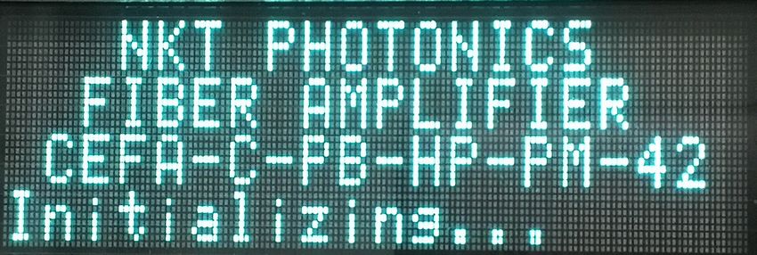
TABLES

Table 1: BOOSTIK HP system optical output................................................................... 11

Table 2: Optical output types .............................................................................................17

Table 3: Emission LEDs........................................................................................................ 18

Table 4: Module labels......................................................................................................... 19

Table 5: CLI terminal emulator settings...........................................................................27

Table 6: CLI command list.................................................................................................. 30

Table 7: Pin assignments..................................................................................................... 31

Table 8: Power specifications ........................................................................................... 32

Table 9: USB-B port pin assignments ............................................................................. 33

Table 10: Optical specifications ....................................................................................... 35

Table 11: Mechanical dimensions .................................................................................... 36

Table 12: Operating and storage environment ............................................................ 36

Table 13: Electrical................................................................................................................ 36

Table 14: Mechanical dimensions ................................................................................... 36

Table 15: Safety and regulatory compliances .............................................................. 36

Table 16: Laser Troubleshooting ...................................................................................... 41

                                             7
8
FIGURES

        Figure 1: Koheras BOOSTIK HP with Koheras ADJUSTIK seed laser ...................... 11

        Figure 2: BOOSTIK HP front panel layout ...................................................................... 13

        Figure 3: BOOSTIK HP rear panel layout ....................................................................... 15

        Figure 4: Front panel display and controls .................................................................... 21

        Figure 5: BOOSTIK HP initializing ................................................................................... 22

        Figure 6: Initialized .............................................................................................................. 22

        Figure 7: Seed laser on ...................................................................................................... 22

        Figure 8: Key in ON position ............................................................................................ 23

        Figure 9: ACC selected ...................................................................................................... 23

        Figure 10: ACC set to a low current setting .................................................................. 23

        Figure 11: ON BLUE LED emission indicator – ............................................................. 24

        Figure 12: Selecting STATUS ........................................................................................... 25

        Figure 13: Status display – no alarms ............................................................................. 25

        Figure 14: Selecting ALARMS ........................................................................................... 25

        Figure 15: ALARMS display – Interlock alarm .............................................................. 25

        Figure 16: DB-15 pin numbering ....................................................................................... 31

        Figure 17: Mechanical dimensions ...............................................................................................37

        Figure 18: Optical output type dimensions ...............................................................................38

        Figure 19: Warranty seal .................................................................................................... 39

white

                                                     9
10
1 Description
The Koheras BOOSTIK HP system is a Continuous Wave Fiber Amplifier (CW) system.
The amplifier produces ultra-bright, near-diffraction-limited, infrared laser light,
delivered to a flexible output fiber and collimating optics.
The amplifier contains reliable, high-brightness diode lasers that pump a double-clad,
ErYb-doped or Yb-doped optical fiber. Microprocessor controlled electronics power
the diode lasers and control the fiber amplifier operation. A heat sink and fan
provides the necessary cooling for reliable operation. All components of the amplifier
are housed within a rack mountable chassis and includes front panel controls and
display.
The Koheras BOOSTIK HP emits TEM00 continuous wave radiation in the 1064nm or
1550nm range with a maximum continuous optical power of 1 to 15 W (depending on
model) at nominal current.
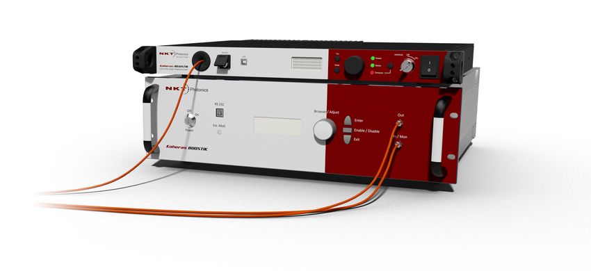
The amplifier can be equipped with a Koheras ADJUSTIK laser as part of an
integrated Koheras BOOSTIK HP system. The Koheras ADJUSTIK acts as a seed laser
when combined with the amplifier. When the amplifier is used in a Koheras BOOSTIK
HP system, the laser’s optical output is defined by an ultra-narrow line width in the
Hertz range and exceptionally low frequency and intensity noise. These
characteristics make the laser suitable for applications such as quantum optics,
computing and other phenomena like optical trapping, optical lattice, Bose-Einstein
condensate, atom interferometer, and squeezing.
Figure 1 Koheras BOOSTIK HP with Koheras ADJUSTIK seed laser
Note: Other lasers that meet the input optical specifications can also be used as a
seed laser with the amplifier.
BOOSTIK HP systems, using the amplifier, have a center wavelength of either 1550.12
nm (E15 model) or 1064.00 nm (Y10 model). However, the system may have a custom
center wavelengths in the ranges of either 1550-1570 nm or 1050-1090 nm. The
output power of the systems depend on the variant and is listed in Table 1 below.
Table 1 BOOSTIK HP system optical output
Model Optical Output Power (W)
E15 2, 5, 10
Y10 2, 5, 10, 15
11Note: Other applications for a BOOSTIK HP system include using it as a linear optics
pump source (SHG, DFG, OPO) and for laser-based metrology.
Configuration ID Koheras modules are defined by their configuration ID which includes the options.
Refer to Appendix F for a list of Koheras BOOSTIK HP configuration IDs.
Amplifier features The amplifier includes the following key features:
• Interlock and Key switch – shuts the laser off upon unauthorized or
accidental access and prevents unauthorized operation.
• Front panel controls and display – operation menu with selection dial and
navigation buttons
• Enable/Disable button with emission LED indicator
• Remote PC control – Command Line Interface over a serial USB connection
• FC connectors for both optical input and output
• 19 inch rack mounting flanges with chassis handles
2
12Front and rear panels
Front and rear panels
Front panel Figure 2 shows the front panel of a BOOSTIK HP amplifier chassis
Figure 2 BOOSTIK HP front panel layout
1 2 3 4 5
6 7 8 9 10 6
1 USB-RS-232 serial port 6 Rack mounts with handles
2 LCD display panel – operation menu 7 Key switch - ON/OFF switch
3 Enter button 8 Selection dial
4 Enable/disable button with emission LED 9 Exit button
5 Optical output – FC/APC connector 10 Optical input – FC/APC connector
USB type B port
Connect the port to a PC to manage the laser from CONTROL.
LED display panel
The display panel provides a control and monitoring interface for the laser. All laser
operations can be undertaken using the display.
Enter button
Enters a display panel menu item or confirms a new value for a parameter.
Emission control button
Pressing the button enables or disables emission from all lasers inserted in the
chassis. The button features a rectangular blue LED which flashes during amplifier
stage warm-up and is continuously ON when emissions are fully enabled.
Warning: When the LED is flashing or ON, dangerous laser emissions are emit-
ted. Take all proper safety precautions necessary. The Koheras BOOSTIK HP
Safety, Handling and Regulatory Information document provides multiple safety
information that should be adhered to along with applicable regional safety regu-
lations.
Optical output
The optical output for the BOOSTIK HP can be one of the following.
13Front and rear panels
• FC/APC connector
• Collimated FC/APC connector
• Collimator
• Collimator/Isolator assembly
The type of optical output included with the amplifier depends on the amplifier
wavelength, power and output number specifications. See “Optical output” on
page 17 for further information.
Rack mounting handles
Use the handles as grips when transporting the amplifier or mounting it in a 19 inch
equipment rack.
Key switch
The key switch must be ON to enable emission. Turn the key to the OFF position and
remove the key to prevent unauthorized laser operation.
Note: If the interlock disables the laser the key switch must be cycled to the OFF po-
sition and then ON again to reset the safety interlock.
Selection dial
The selection dial moves the front panel prompt between menu items and modifies
the amplifier current settings.
Exit button
Exits from a lower level menu to the top menu level.
Optical input
1 meter FC/APC connector pig tail. However the BOOSTIK HP can be specified with
multiple outputs and inputs for integration with for example an Koheras ACOUSTIK
chassis with multiple Koheras BASIK modules.
14Front and rear panels
Rear panel Figure 3 shows the rear panel is made up of multiple connectors and a large cooling
fin array to maintain the BASIK modules at an optimum operational temperature.
The panel provides connectivity for control signals, safety interlock, accessories, and
AC mains.
Figure 3 BOOSTIK HP rear panel layout
1
5
2 2 3 4
1 AC mains ON/OFF switch 3 Interlock connectori
2 Cooling fans 4 AC mains input
i. Interlock pin assignments – see Appendix Connecting the safety interlock
Note: The pin assignments of the Interlock are described in “Connecting the BOOS-
TIK HP” on page 31.
AC mains switch
Press ( I ) to turn on the amplifier and ( 0 ) to turn it off.
Cooling fans
The fans blow hot air out from the chassis, ensure there is adequate clearance for
proper airflow.
AC mains input
AC inlet - standard IEC C-14 mains inlet connector - see “Connecting power” on
page 32.
Interlock
Male DB-15 connector – connect to a safety interlock switch which is operated by the
access door to the laser operational area. “Connecting the safety interlock” on
page 31.
Warning: DO NOT BYPASS the interlock by jumping the pins on the connector.
Laser regulations require that the interlock is connected to a safety door switch.
When the door switch circuit is open the laser is immediately disabled.
15Front and rear panels
Warning: The Koheras BOOSTIK HP system has built-in safety relay and interlock
features to help ensure laser radiation is emitted only when desired and only when
predetermined conditions are met.
The Koheras BOOSTIK HP system has built-in safety relay and interlock features to
help ensure laser radiation is emitted only when desired and only when
predetermined conditions are met.
The remote interlock and remote stop features render the system inoperable when a
predefined condition occurs, such as the opening of a door. The internal safety relay
is analogous to a beam shutter. It interrupts drive current to the diode pump lasers,
and it is open each time the system is turned on. This means it will be impossible to
apply current to the diode pump lasers until you close the circuit and reset the front
panel key switch.
16Optical output
Optical output
Optical output can be one of five types. The type used is dependent on the amplifier
power level, wavelength and on some models the output number. Refer to Table 2
below for details.
Note: For dimensions of the Optical output types, refer to Figure 18 on page 38.
Table 2 Optical output types
Optical output type
Wavelength Output Fiber Collimated Collimator Collimator Collimator
(nm)& fiber type power (W) length FC/APC only with Isolator with isolator
(m) type 1 type 2
10xx PM 2 2
1030 PM 5 2
1050 PM 5 2
1064 PM 5 2
10xx PM 10 1.5
15 1
1550-1570 PM 2 2
5 2
10 1.5
15 1
1550-1570 SM 2 2
Multiport 1 i
i. Standard FC/APC connector (non-collimated)
Miscellaneous
Safety
Warning: The lasers output from the chassis is rated as class 4 laser and is there-
fore hazardous. Before turning on the BOOSTIK HP and connected seed laser,
ensure to read and understand all safety statements of the document:
Koheras ACOUSTIK Safety, Handling and Regulatory Information
A paper copy of this document is included with your laser. If you do not have access
it, you can download a copy from:
https://www.nktphotonics.com/lasers-fibers/support/product-manuals/
17Managing the amplifier
Managing the amplifier
Operations The amplifier is operated either from the front panel or through a Command Line
interface Interface accessible through the USB RS-232 connection on the front panel.
“Operating the BOOSTIK HP Amplifier” on page 21 includes information on how to
operate the amplifier with both interfaces.
Emission LEDs
The Emission Enable/Disable button on the front panel houses an Emission LED LED
as described in Table 3. The LED is located in the center of the button as shown in
Figure 2.
Table 3 Emission LEDs
LED Name Condition Description
Emission ON Blue Laser emission is ON.
OFF Laser emission is OFF.
Note: DO NOT OPERATE the BOOSTIK HP until you are familiar with the controls and
have taken all precautions necessary as described in the document: Koheras BOOS-
TIK HP Safety, Handling and Regulatory Information.
18Chassis labels
Chassis labels
A Koheras BOOSTIK HP chassis has a number of labels on it that indicate hazards,
regulatory, or manufacturing information. The labels are located on the panels
described in Table 4.
Table 4 Module labels
Label Panel Description
Classification - Top Safety information stating the laser emission
Emission hazards and the laser’s class rating.
Hazards
Product Top Safety label showing the emission
Information specifications of the laser.
Laser Radiation Front Safety information alert indicating this
Warning area of the laser is near a source of
dangerous laser emissions.
19Chassis labels
202 Operating the BOOSTIK HP Amplifier
A BOOSTIK HP amplifier is controlled and operated using either the:
• Front panel interface – described in “Front Panel Operation” on page 21
– or –
• Command Line Interface (CLI) from a connected PC – described in
“Command Line Operation” on page 27
Front Panel Operation
The front panel features an LED display panel and controls that can be used to
configure and operate the laser amplifier. as shown in Figure 4. They include:
• an LED text display – displays amplifier current level, optical input power and
alarms.
• a selection dial – selects between current and status menu items; adjusts the
current level.
• enter and exit buttons – to enter and exit into and from menu items.
• an emission button with blue LED emission indicator – to enable and disable
emission
Figure 4 Front panel display and controls
Enable/Disable
Enter button button
LED display panel Selection dial Exit button
Caution: DO NOT ENABLE EMISSION UNLESS THE SEED LASER IS CONNECTED
and ENABLED. Enabling the amplifier emission without suitable seed laser input
may DAMAGE the amplifier.
21Front Panel Operation
Switching AC power 1. To apply AC power to the amplifier, press the rear AC mains button to the ( I )
ON position.
2. The cooling fans should immediately start and the front panel screen will
display an initialization screen as shown in Figure 5.
Figure 5 BOOSTIK HP initializing
Connect and switch When the amplifier has initialized, the display shown in Figure 1 indicates there is
ON the seed laser NO INPUT POWER and the front key switch is (KEY) OFF.
1. Connect the seed laser’s optical output to the optical input of the BOOSTIK
HP amplifier (see - “Connecting the optical input from a seed laser” on
page 33).
Figure 6 Initialized
2. Enable emission on the seed laser. The Pin (Power input) field in the front
panel display shows the received emission power level as shown in Figure 7.
Figure 7 Seed laser on
2
Turn the key ON 1. To reset the interlock and turn on the preamplifier, turn the front panel key to
the ON position. The display changes the STATUS field to KEY ON as shown
in Figure 7.
Warning: With the connected seed laser ON, the Koheras BOOSTIK HP outputs an
optical power of approximately 300mW. Avoid eye exposure to the beam.
22Front Panel Operation
Figure 8 Key in ON position
2. When the key is in the ON position and the input optical power is acceptable for the
amplifier, the emission (Enable/Disable) button LED will flash BLUE for 30 seconds
during stabilization.
3. After 30 seconds of stabilization, the amplifier is ready for operation
Note: The emission button LED flashes BLUE when emission is possible ONLY. This
means the optical input received by the amplifier is acceptable and the interlock circuit is
closed and reset (KEY ON) and no other alarms exist.
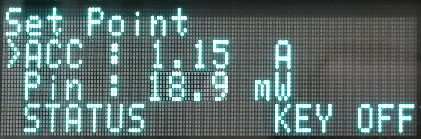
Set the 1. Turn the selection dial until the prompt ( > ) points to the ACC (Amplifier Current
Amplifier Control) setting as shown in Figure 9.
Current
Control Figure 9 ACC selected
2. Press the enter button to select the ACC setting.
3. Turn the selection dial to modify the ACC level. Range 0 to 8.5 amperes.
4. Press the exit button sets the ACC level.
Warning: Use a low current setting when initially operating the laser amplifier in a new ap-
plication, The current setting can be turned to a higher value once the beam path is de-
termined to be safe.
Figure 10 ACC set to a low current setting
23Status and Alarms
Enable Emission 1. To enable emission, press the emission (Enable/Disable) button on the front
panel.
Caution: DO NOT ENABLE EMISSION UNLESS THE SEED LASER IS CONNECTED
and ENABLED. Enabling the amplifier emission without suitable seed laser input
may DAMAGE the amplifier.
Warning: Enabling emission from the BOOSTIK HP amplifier will emit hazardous
laser Class 4 radiation from the optical output of the chassis. Ensure to observe
and implement all safety regulations, warnings and cautions in this guide and the
Koheras BOOSTIK HP Safety, Handling and Regulatory Information document
before enabling emission.
Warning: Even at very low current settings near 0 A, the fiber amplifier may emit
an optical beam up to 1.6 W. The level is strongly determined by the amplifier con-
figuration, current level setting and wavelength used.
2. When emission is enabled, the emission button LED flashes BLUE for 10
seconds during warm-up. When warm-up is completed the LED turns ON
BLUE, see Figure 11.
Figure 11 ON BLUE LED emission indicator –
Enable / Disable
Flashing BLUE – emission disabled
ON BLUE – emission enabled
Disable emission 1. To disable emission, press the emission button. The BLUE LED extinguishes
and the emission is disabled.
Warning: Hazardous emission is still present when the key switch is in the ON po-
sition and emission is disabled.
Status and Alarms
The lower field in the front panel display will show either STATUS or ALARM. If
STATUS is displayed no ALARMS are existing. If ALARM is displayed an ALARM
exists.
Status display
1. Use the selection dial and move the prompt ( > ) to the STATUS field as
shown in Figure 12.
24Status and Alarms
Figure 12 Selecting STATUS
2. Press enter to display the idle amplifier current and internal temperature as
shown in Figure 13.
Figure 13 Status display – no alarms
Alarm display
1. When an alarm exists, ALARMS is shown on the top menu in the front panel
display. Use the selection dial and move the prompt ( > ) to the ALARM field
as shown in Figure 14.
Figure 14 Selecting ALARMS
2. Press enter to display the existing alarms. Figure 15 shows there is an
existing interlock alarm.
Figure 15 ALARMS display – Interlock alarm
Alarms Some alarms are permanently checked by the amplifier: INTERLOCK,
TEMPERATURES LIMIT and CURRENT LIMIT.
The amplifier signal is automatically stopped when:
• Interlock is not present.
• Ambient temperature is too high.
25Status and Alarms
• Lasers diode temperature (TL) > (TL)max
• Optical core module temperature (TC) > (TC)max
• Laser current > Max CURRENT LIMIT (typical value : 8A)
Note: The alarm threshold values are set during the manufacturing process and
can only be changed by NKT Photonics. Max CURRENT LIMIT varies with each
amplifier, but it is always adjusted to protect the pump diode.
26Command Line Operation
Command Line Operation
The BOOSTIK HP amplifier can be operated remotely using a command line
interface (CLI) from a PC connected to the front panel USB serial port.
DO NOT ENABLE EMISSION UNLESS THE SEED LASER IS CONNECTED and
ENABLED. Enabling the amplifier emission without suitable seed input may
DAMAGE the amplifier.
Connecting the PC 1. Turn the BOOSTIK HP on following the instructions in “Switching AC power
ON” on page 22.
2. Using a Type A to Type B connector, connect the PC to the BOOSTIK HP.
3. If you are using Windows, wait for it to install an appropriate driver for the RS-
232 Serial USB port. Once the driver is installed, the USB COM port will be
available for use.
4. If your PC cannot automatically install an appropriate RS-232 USB driver,
install a driver such as CDM2.04.06.exe or similar.
5. When the PC connects over USB, the front panel display on the amplifier will
show “Remote Control”.
Launch and connect Your PC requires a terminal emulator to connect to the BOOSTIK HP and issue
a terminal window CLI commands.
1. Launch the terminal emulator and use the settings in Table 5 to connect it to
the BOOSTIK HP amplifier.
Table 5 CLI terminal emulator settings
Parameter Setting
Baud rate 9600
Data bits 8
Parity N
Stop bits 1
Flow control N
End of line CR + LF
characters
Local echo ON
2. In the terminal emulator window, press ENTER, a question mark (?) prompt
should appear as below indicating you are connected to the BOOSTIK HP:
?
27Command Line Operation
Check the amplifier 1. Issue the command: “CDI”. The amplifier should respond with the NKTP
information serial number of the unit.
?
CDI
NKT1900008
?
Connect and switch 1. Connect the seed laser’s optical output to the optical input of the BOOSTIK
ON the seed laser HP amplifier (see - “Connecting the BOOSTIK HP” on page 31).
2. To display the input power, issue the command: “CMP 1”, to the amplifier:
CMP 1
192
?
3. “192” shown above is the input power, which is in units of 10-4 amperes.
Turn the key ON 1. To reset the interlock and turn on the preamplifier, turn the front panel key to
the ON position.
Warning: With the connected seed laser ON, the Koheras BOOSTIK HP outputs an
optical power of approximately 300mW. Avoid eye exposure to the beam.
2. After 30 seconds of stabilization (flashing BLUE emission LED), the amplifier
is ready for operation
Note: The emission button LED flashes BLUE when emission is possible ONLY.
This means the optical input received by the amplifier is acceptable and the inter-
lock circuit is closed and reset (KEY ON) and no other alarms exist.
Set the Amplifier 1. Enter the ACC command to set the current level set point in the BOOSTIK HP.
Current Control The command is issued with a current value as a parameter:
ACC .1
0.10
?
Note: When entering ampere values below 1 omit the leading zero before the
decimal point.
2. Check the ACC set point value after modifying it by issuing the ACC
command without a parameter:
ACC
28Command Line Operation
0.10
?
Warning: Use a low current set point when initially operating the laser amplifier in
a new application, The current set point can be turned to a higher value once the
beam path is determined to be safe.
Enable Emission 1. To enable emission, issue the “CDO” command with the enable parameter
“1”:
CDO 1
1
?
Caution: DO NOT ENABLE EMISSION UNLESS THE SEED LASER IS CONNECTED
and ENABLED. Enabling the amplifier emission without suitable seed laser input
may DAMAGE the amplifier.
Warning: Enabling emission from the BOOSTIK HP amplifier will emit hazardous
laser Class 4 radiation from the optical output of the chassis. Ensure to observe
and implement all safety regulations, warnings and cautions in this guide and the
Koheras BOOSTIK HP Safety, Handling and Regulatory Information document be-
fore enabling emission.
Warning: Even at very low current settings near 0 A, the fiber amplifier may emit
an optical beam up to 1.6 W. The level is strongly determined by the amplifier con-
figuration, current set point and wavelength used.
2. When emission is enabled, the emission button LED flashes BLUE for 10
seconds during warm-up. When warm-up is completed the LED turns ON
BLUE, see Figure 11.
Disable emission 1. To disable emission, issue the “CDO” command with the disable parameter
“0”:
CDO 0
0
?
2. The BLUE emission LED extinguishes and the emission is disabled.
3. Check that the BOOSTIK HP is disabled using the command “CDO” without
any parameter:
CDO
0
?
29CLI Command list
If the BOOSTIK HP is disabled the CLI will return a “0”.
Warning: Residual emission is still present.
CLI Command list
Along with the commands previously used, status information can also be
retrieved. Table 6 lists all commands available with the CLI.
Table 6 CLI command list
Command Parameteri Description
ACC (0.0 to 8.5) No parameter – displays the set point current level.
With parameter – modifies the set point in Amperes.
(ACC mode)
AMC – Displays the actual current level while enabled.
AMT 1 Displays the temperature of the diode/booster.
CMA – Displays the ambient temperature.
CMP 1 Displays the input optical power level.
CDO (0,1) No parameter returns the amplifier enable status. 1
enables the amplifier i.e. ON, and 0 disables it i.e. OFF.
CDI – Returns the amplifier information.
i. Parameters in parenthesis are optional
Command syntax Commands are entered at the CLI “?”prompt and issued to the BOOSTIK HP by
pressing the ENTER.
If a parameter is required, a space must separate the parameter from the
command.
303 Connecting the BOOSTIK HP
This chapter focuses on the relevant details of electrical and optical connections
to the amplifier.
For information on connecting:
• the Safety Interlock – see “Connecting the safety interlock” on page 31.
• power – see “Connecting power” on page 32.
• PC to BOOSTIK HP communications – see “USB PC connection” on page 33.
• Seed laser input – see “Connecting the optical input from a seed laser” on
page 33.
Connecting the safety interlock
To comply with safety regulations and help provide a safe operating
environment, the safety interlock of the BOOSTIK HP chassis must be connected
to a switch activated by an access door to its operating area. The interlock circuit
detects when the door switch opens and immediately disables emission.
Interlock The door interlock circuit is connected to the female DB-15 connector on the rear
connection panel (see Figure 3). Connect the circuit to the pins shown in table x.
Table 7 Pin assignments
Pin #i Description
1 Interlock ground
9 Interlock
i. Pins positions shown in the
figure below.
Figure 16 DB-15 pin numbering
1 13
…
14 25
Caution: Do not short-circuit the Interlock input. Short-circuiting the interlock cir-
cumvents safety regulations and NKT Photonics does not take liability for any in-
juries or damage caused by doing so.
31Connecting power
Caution: The switch connected to the interlock must be of an approved type. Fur-
ther, the switch must be installed in a manner so that its operation cannot be fixed
in the open state using a tool.
Warning: If the interlock is bypassed using an interlock defeater, personnel may
be exposed to hazardous laser radiation. To reduce the risk to personnel, the per-
son or group responsible for operation of the equipment must undertake a risk as-
sessment and provide personnel with appropriate personal protective equipment
and safety training.
Connecting an Follow the steps in Procedure 1 to connect a safety door switch to the interlock
interlock switch circuit of the laser.
Procedure 1 Connecting the door interlock circuit
Action
1 Install a switch that opens when the door accessing the BOOSTIK HP enclosure is opened.
The switch must comply with safety regulations.
2 Use a cable with a maximum wire length of five meters and at a minimum 26 AWG, connect
the switch to the rear DB-15 interlock connector. For cable lengths longer than five meters,
it is recommended to use shielded cable.
3 Perform a continuity test using a multimeter:
• First connect the multimeter leads to the interlock plug terminals.
• Confirm when the enclosure door is closed, the meter shows the circuit as closed.
• Confirm when the enclosure door opens, the meter shows the circuit as open.
Connecting power
Power is supplied to the laser through the rear AC input connector. The
connector is a standard C-14 type designed for use with an AC power cord that is
fitted with a C-13 connector. Electrical and cable specifications are listed in
Table 8.
Table 8 Power specifications
Item Description
AC Mains 88-264 VAC @ 47-63 Hz 2
Inputi
Power cord The power cord must be capable to safely transmit the laser’s specified AC
ratings whilst maintaining a safe connection with the local AC mains outlets.
The power cord used must follow local or national regulations.
AC connector IEC 60320 – C14
(inlet)
Power cord The power cord must have an IEC 60320 C-13 connector for proper connection
connector with the BOOSTIK HP AC inlet.
i. T= 20C, P=10W
32USB PC connection
USB PC connection
Using a USB-A to USB-B cable, connect a PC to the USB-B port on the front panel
of the BOOSTIK HP. The port supports RS-232 communications requiring the PC
to implement a USB to RS-232 driver.
Table 9 lists the pin assignments for USB-B connector on front panel
Table 9 USB-B port pin assignments
Pin # Description
1 VCC USB (+5 VDC)
2 DATA -
3 DATA +
4 Ground
Connecting the optical input from a seed laser
Seed input The Koheras BOOSTIK HP optical input is equipped with a 1 m pig-tail
connection connecterized fiber. The default connector at the end of the pig-tail is an FC/APC
connector.
Using an appropriate optical fiber coupler, connect the seed laser optical output
connector to the input connector of the BOOSTIK HP amplifier.
Caution: Before connecting the input optical connectors, ensure to check the con-
nector tips using a fiber microscope. Using a microscope, check for any deformi-
ties, damage, residue or other contaminants at the optical tip of each connector.
Either clean the connectors or contact NKT Photonics support if replacement is
necessary.
Caution: DO NOT ENABLE EMISSION UNLESS THE SEED LASER IS CONNECTED
and ENABLED. Enabling the amplifier emission without suitable seed laser input
may DAMAGE the amplifier.
Warning: ENSURE the seed laser is DISABLED when connecting its output to the
input of the amplifier.
33Connecting the optical input from a seed laser
34A Specifications
Table 10 Optical specifications
E15 Y10
Center Wavelengthi 1550- 1570 1050 - 1090
Laser Emission CW - inherently single frequency CW - inherently single frequency
Beam Quality (M2) M2 < 1.1 @ 2 W output M2 < 1.1 @ 2 W output
M2 < 1.1 @ ≥ 5 W output M2 < 1.3 @ ≥ 5 W output
Output power [W]ii 2, 5 or 10 2, 5, 10 or 15
Output power regulation [%] iii 30 - 100 30 - 100
Linewidth (kHz) 65 (typically > 70)
Polarization Linear (PM) Linear (PM)
Min. Thermal Tuning Wavelength Tuning +/- 350 +/- 240
Range (pm)
Total thermal wavelength tuning range [pm] 1000 700
Optical S/N (50 pm res.) (dB) > 50 (typically > 55) > 65 (typically > 70)
Fast Wavelength Modulation range (GHz) 8 10
Fast Wavelength Modulation (KHz) up to 20 up to 20
Optical monitor output (from seed) FC/APC FC/APC
Output fiber termination FC/APC @ 2 W output FC/APC / collimator @ 2 W output
Collimator @ ≥ 5 W output Collimator @ ≥ 5 W output
Typical beam diameter @ 1/e2 FC/APC @ 2 W FC/APC / < 2.2 mm
≈2 mm @ 5 and 10 W < 1 mm @ 5 and 10 W
Output isolation [dB] > 35 > 30
i. The center wavelength is selectable within the specified range. Contact NKT Photonics for options outside the range.
ii. Depends on the center wavelength.
iii. The range can be larger depending on the center wavelength and output power.
iv. Lorentzian
v. Shot-noise limited > 5 MHz
35Table 11 Mechanical dimensions
All chassis models
Size (H x W x D) 132 x 482 x 448.5 mm (5.20 x 18.98 x 19.23in)
Rack Dimension 19” x 3U
Weight 180 W
i. Dependant on the amplifier ratings, contact NKT Photonics support.
Table 14 Mechanical dimensions
All chassis models
Size (H x W x D) 130 x 463 x 348 mm
(5.12 x 18.23 x 13.70 in)
Weight ~ 10 kg (~22 lb)
2
36Figure 17 Mechanical dimensions
37Figure 18 Optical output type dimensions
Collimated FC/APC
Collimator only
Collimator with isolator
type 1
Collimator with isolator
type 2
38B Service and support Information
Servicing the laser
The laser have no user serviceable components. In case of malfunction, contact
NKT Photonics using the support channels in section “Support contact details”.
Caution: Do not open the laser’s modules. The laser modules are equipped with
warranty labels (see Figure 19) on the covers of the laser chassis. The warranty is
void if the system is opened.
Figure 19 Warranty seal
Caution: The laser contains electro-static discharge (ESD) sensitive components.
To avoid permanent ESD damage, use ESD protection precautions when han-
dling the laser. Always connect the laser’s earth point to a ground earth within
your facility.
Opening the laser There are no user serviceable components inside the laser chassis. Should your
chassis laser malfunction, and it cannot be serviced on site, it must be shipped to the
NKT Photonics office in Birkerød, Denmark.
WARRANTY VOID The unit is sealed with a label “WARRANTY VOID IF REMOVED”. It is strictly
IF REMOVED Label prohibited to remove the chassis cover
39Support contact details
Support contact details
For technical or general support, NKT Photonics can be contacted for help
regarding issues and questions with your laser or its accessories.
Support Email support@nktphotonics.com
Online support http://www.nktphotonics.com (click on support)
web-page
Shipping address NKT Photonics A/S
Blokken 84
DK-3460 Birkerød
Denmark
2
40C Troubleshooting and Errors
Troubleshooting
Table 16 Laser Troubleshooting
Symptom Action
The amplifier cannot be turned ON 1. Make sure that the communication link (USB serial) between the PC and the
when the enable command is amplifier is working.
issued and sent to the amplifier. 2. Check the Interlock connection, door switch and the circuit loop is closed.
3. Check for existing alarms on the front panel display.
There is no communication 1. Make sure that the terminal emulator parameters are correct (Table 5).
between the amplifier and the PC 2. Check the USB RS232 cable.
Low output power 1. Check for any over bending of the collimator flexible tube.
Output power instability 1. Check for potential optical signal reflection back into the collimator.
Alarm temperature 1. Check that there is clearance space in the front and the back of the amplifier
for adequate air circulation.
41Troubleshooting
2
42Koheras BOOSTIK HP Product Guide Revision 1.0 02-2020 W-10456
You can also read