Human Motion Energy Harvesting Using a Piezoelectric MFC Patch
←
→
Page content transcription
If your browser does not render page correctly, please read the page content below
Human Motion Energy Harvesting Using a Piezoelectric MFC Patch
Giulia Bassani1 , Alessandro Filippeschi1 and Emanuele Ruffaldi1
Abstract— The improvements in efficiency of electronic com- There is an impelling need of a new technology to harvest
ponents and miniaturization is quickly pushing wearable de- biomechanical energy that does not require the user to make
vices. Kinetic human energy harvesting is a way to power these specific actions to generate energy; to carry a cumbersome
components reducing the need of batteries replacement since
walking or running is how humans already expend much of and heavy load that cause additional metabolic cost; to
their daily energy. This work explores the case of kinetic energy wear shoes that can cause postural problem in people who
from bending of a piezoelectric patch. For assessing the quality habitually go jogging and want to use their specific shoes; or
of the system, a testing setup has been designed and controlled for post-traumatic patients who even can’t load on their legs.
by means of knee joint recordings obtained from a large motion The development of effective, reliable and low-cost sensors
dataset. The promising result of the chosen patch is an output
power of 2.6µW associated to a run activity. for the human body with embedded power generation needs
relevant innovation in optimizing the efficiency of power
I. INTRODUCTION harvesting from ambient sources, which are generally irreg-
In the past decade, we have become increasingly depen- ular and small. Innovative transduction devices and materials
dent on portable electronic devices since technology has need to be investigated, characterized and validated.
been developing rapidly [1]. Wireless networks composed Recently developed composite materials allow harvest-
of autonomous sensor nodes will be key elements of the ing energy from large bending motions without reliability
future intelligent environment. Such systems have already limitations, thanks to the aid of piezoelectric fibers [8],
been developed for medical applications [2]. [9], which show relevant advantages with respect to rigid
Power autonomy of the sensor nodes is essential for their and fragile traditional piezoceramic sheets [10]. This is the
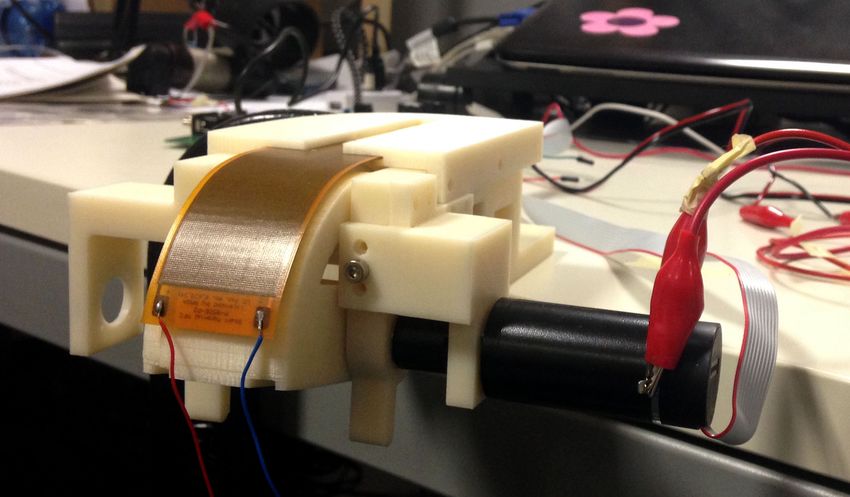
success, and this requires the development of low-power case of Macro-Fiber composites (MFC) tested in this work
electronics and of long-life energy sources. The current [11]. They are characterized by their flexibility on large
approach for powering them is battery, which add weight, deformation (Figure 2), which enables them to harvest energy
size and inconvenience to the user. There is a need to promote directly from large human limb motions rather than exploit
alternative sustainable power sources. Smart wearable sys- their resulting vibrations. The latter would entailed a resonant
tems, endowed with autonomous sensing, actuation, process- employment of the piezoelectric transducer often causing
ing, communication and energy harvesting and storage, are issues in developing damping systems in wearable devices.
emerging as a solution to the challenges of monitoring people To the authors knowledge, at the state of the art there
anywhere and at anytime in applications such as health- are no studies testing the MFC power output from specific
care, well-being and lifestyle, protection and safety [3]. human activities under non-resonant bending conditions. In
Recent advances in the field of energy harvesting have led this work, we proposed a method to test the MFC power
to the development of efficient and sustainable technologies output thanks to a mechanical framework specifically de-
that are capable of collecting mechanical energy produced signed to reproduce the kinematic of a knee joint and actu-
by human motion [4]. Walking, as a routine activity has ated using recorded human motion patterns. Following the
great potentials for biomedical energy harvesting, namely introduction, a description of the energy harvesting system
leg motions, i.e., ankle, knee, and hip motions, heel strikes, and a presentation of the experiments are given in Section
center of mass motion, shoulder and elbow joint motions II. The results are presented and discussed in Section III
during arm swings. For example: the self-winding watch and the conclusions of the study are presented in Section
that utilizes the motion of the user’s arm to accelerate IV, along with an examination of possible future work and
a small internal mass produces 5µW [1]; the suspended- improvements.
load backpack that exploit the motion of the center-of-mass
relative to the ground to generate 7.4W during fast walking II. MATERIALS AND METHODS
carrying a 38Kg load [5]; the 1.6-kg knee joint device based
on negative work of the muscles [6] that generates 2.5W per A novel non-resonant energy harvesting mechanism with
knee at a walking speed of 1.5m/s; or the many researches wide operation frequency band is investigated for collecting
to harvest the heel strike collision energy which is estimated energy from low-frequency human joint motion. The energy
to be up to hundreds of mW [7]. harvesting system (Figure 1a) is composed by the P2-type
MFC piezoelectric patch [12] attached to a mechanical
*This work is supported by Telecom Italia structure purposely-built to reproduce human joints motion
1 Authors are with PERCRO, TeCiP Institute,
Scuola Superiore Sant’Anna, 56100, Pisa, Italy approaching one degree of freedom, as elbow or knee. The
{g.bassani,e.ruffaldi}@sssup.it structure is actuated by a DC motor thanks to an ARM
978-1-4244-9270-1/15/$31.00 ©2015 IEEE 5070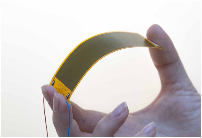
microcontroller board along with the motor driver and an         is acquired by the ADC chip AD7656 (Analog Devices),
analog-to-digital (ADC) to acquire the MFC’s power output.       configured as 16 bit, 250 kSPS, ±5V , whose selection is
                                                                 discussed later in the paper. The DC motor position control
                                                                 is a Proportional-Integral-Derivative (PID) kind integrated in
                                                                 a dedicated interface to program the ARM microcontroller
                                                                 board implemented in Mathworks Simulink.

                                                                 B. Assessment Design
                                                                    Since every energy harvesting system combines two dif-
                                                                 ferent sub-systems, a mechanical one and electrical one, both
                                                                 have to be designed very carefully. Only if both interfaces
   (a) MFC bending test setup.        (b) Mechanical frame.      match their direct connected environment, the mechanical
                       Fig. 1: Test setup.                       load conditions, as well as the charge electronics input
                                                                 characteristics, a high degree and efficient harvesting of
                                                                 kinetic human energy can be observed.
A. System Design                                                    First, we performed a preliminary characterization of the
   The Macro-Fiber Composite (MFC), recently developed           energy harvesting system, since human movements cover a
at NASA Langley Research Center [13], is a planar piezo-         wide frequency and amplitude ranges and accordingly the
electric device consisting of a sheet of aligned rectangular     voltage output levels can be very different. This implies the
piezoceramic fibers embedded in an epoxy matrix, that            use of an external ADC with higher input voltage range
inhibits crack propagation, and sandwiched between layers        besides a higher conversion resolution, in order to obtain
of interdigitated electrode pattern on polyimide film, that      a trustworthy output power. Then, the other issue was to
grant a higher electromechanical coupling coefficients. This     determine the optimal condition to have the maximum energy
approach improves damage tolerance and flexibility relative      transfer. Figure 3 shows the basic dipole model which is
to monolithic ceramic. The P2-type MFC [12], which utilizes      generally used to characterize electric power sources. The
the d31 effect (Figure 2) is especially suited for energy        source with the potential V q drives a current I through the
harvesting applications and it allows to harvest energy from     in-series connected resistors Rin for the inner resistance of
large bending motions without reliability limitations.           the power source, and Rout for the electrical load. Based
                                                                 on this model the general relations for the efficiency and
                                                                 power transfer can be defined. The efficiency is the power
                                                                 transferred into the electric load related to the total power in
                                                                 the source (Equation 1) as a function of the resistors.

                                                                                          Pout      Rout
                                                                                     η=        =                             (1)
                                                                                          Pin    Rin + Rout
                                                                    It becomes clear that by increasing the resistance of the
Fig. 2: Macro-Fiber Composite (MFC) piezoelectric patch          load resistor the efficiency converges to a value of η = 1.
                                                                 However, real input impedances of current state-of-the-art
   The mechanical frame (Figure 1b) has been designed in         systems for electronic charge control and collection do not
SolidWorks and printed with a 3D printer Dimension Elite         meet the perfect value for a load resistor, so efficiency
P14941 (Stratasys) in ABS+P430IVR with slice thickness:          will be always below 1. Since the inner impedance of the
0,178 mm. Besides the main fixed frame, it is composed by        piezoelectric patch is fixed, to optimize the power transfer
a revolving frame that allows the MFC patch bending, a rail      from the power source into the electric load, we performed
to let the patch slide into, and the motor frame.                some tests to detect the optimal load value, as we will see
   There are two limit positions to avoid the patch to be        better in the next section.
over-bent: when the revolving frame is in vertical position
the patch is straight into the rail, and moving until the
                                                                                  Rin      I
max bending stop, energy is generated. We actuated and
sensed the structure with a Maxon motor modular system                                                 Rout
composed of a DC brushed motor and an encoder to monitor                                                      Pout
                                                                                               Vout
the patch bending-angle. They are both connected to the
circuit board: a STMicroelectronics board, based on an ARM                     Pin
                                                                                          Vq
microcontroller (STM32F407VGT6 Cortex-M4 32-bit RISC,
168 MHz) integrated with a Pololu motor driver (VNH5019),
a fully integrated H-bridge that can be used for bidirec-
tional speed control of the motor. The patch voltage output            Fig. 3: Dipole model for electric power sources

                                                              5071
After having established the overall setup, we gave thought optimal load value (R = 470 KΩ). We tested sixteen different
to the motor control input. In this work no experiments with resistances with a run/jog activity (1.29Hz, 83.5◦ ) system
humans have been performed. We extracted human motion input.
data from the Carnegie Mellon University (CMU) motion
capture database1 , a free dataset of motions classified by 1
Power Output [uW]
subject number or motion category and recorded by means of Current output [uA]
a marker-based motion capture system. The 3D data obtained 0.5
Voltage output [V]
can be arranged in different ways; we used the skeleton
movement one that consists in an .asf/.amc pair of files. 0
The former element of the pair describes the skeleton and
its joints: their connections, lengths, degrees of freedom, −0.5
and mathematical transformations. Instead, the latter element
contains the movement data. We fused and extracted the −1
0 1 2 3 4 5
knee flexion position data (Figure 4) to control our motor2 Resistance [MΩ]
and simulate motions to test in term of harvestable energy.
Fig. 5: Measured outputs used for selection of optimal load
The knee is a very important joint for energy harvesting
resistance
purpose due to motion amplitude, its angular range is around
120◦ with an extra range of 40◦ , to the imposed force and
frequency of use, given that walking or running is how The output signals, voltage drop across the optimum
humans already expend much of their daily energy. For resistance and angular position, are measured simultaneously
actuating the energy harvesting system we selected walking by the ADC and by the microcontroller board acquisition
and running actions from the CMU motion database spanning system respectively, in order to correlate the output power
frequencies and styles of action. with the angular position of the joint.
As expected, we can pleasantly point out that the main
parameter influencing the energy harvesting power output is
90
the motion amplitude (Table I). There is an almost monotonic
80
dependency on the motion amplitude (Figure 6), the bigger
Knee flexion angle [Deg]
70
it is the bigger the power output is and when the movement
60
range is over 100◦ there is a power output boost of one
50
order of magnitude. On the contrary, the frequency is not
40
very influencing the energy harvesting power output; from
30
the table I we can see that the higher frequencies did not
20
generate the bigger amount of energy.
10
0 3 1 2
0 0.5 1 1.5 2 2.5 3 3.5 4 4.5 5
Voltage output [V]
Time [s] Current output [uA]
2.5
Power Output [uW]
0.8 1.5
Power Output [uW]
Current output [uA]
Fig. 4: Typical knee flexion-extension angle trend during
Voltage output [V]
2
walking
1.5 0.6 1
For the assessment we performed sixteen acquisition trials 1
with data belonging to seven different subjects with different 0.4 0.5
0.5
body geometries and, important thing for this study, with
different walking or running styles, in the sense of different 0 0.2
50 60 70 80 90 100 110 120
0
motion amplitude and frequency values, even between the Max Knee Angle [deg]
two subjects knees in the same trial. This allowed attaining Fig. 6: Measured outputs on the chosen motion set
a long range of knee flexion motions, spanning from 0.8
Hz to 2 Hz and from 60◦ to 115◦ , see table I, as excitation
sources for the energy harvester system. B. Discussion
The innovative electromechanical transducers developed
III. EXPERIMENTAL RESULTS AND DISCUSSION allows to reach power output levels sharply over those of
A. Results similar devices [14] currently at the state-of-the-art in re-
In piezoelectric transducers, the function describing the search on piezoelectric energy harvesting systems exploiting
output power with reference to the applied load has an human joints motion.
absolute maximum (Figure 5) and it is easy to choose the The experimental results on the dedicated test bench
reported in the previous section can be used to estimate
1 http://mocap.cs.cmu.edu/ the power harvested from specific human activities. For
2 https://github.com/eruffaldi/paper_zp_embc15 instance, by considering the flexion-extension motion of the
5072CMU name Action Amax (deg) f (Hz) Vpp (V) Vavg (V) Pavg (uW) Iavg (uA)
35 01 Left Fast Walk 59.7 1.79 1.358 0.3099 0.2766 0.6579
08 01 Right Fast Walk 61.2 1.96 2.428 0.4373 0.5823 0.9282
06 01 Left Walk 62.7 0.82 1.318 0.2143 0.1354 0.4549
16 36 Left Run 65.3 1.29 1.472 0.3819 0.3954 0.8107
35 01 Right Fast Walk 65.3 1.79 1.435 0.3172 0.3024 0.6732
06 01 Right Walk 68.9 0.83 2.187 0.3827 0.4416 0.8124
08 01 Left Fast Walk 73.2 1.99 3.212 0.4342 0.6436 0.9218
16 36 Right Run 79.14 1.26 1.919 0.3665 0.4376 0.7779
02 03 Right Run/Jog 83.5 1.29 1.983 0.4960 0.6713 1.0528
02 03 Left Run/Jog 87.6 1.41 1.451 0.3977 0.4170 0.8443
35 26 Left Run/Jog 89.9 1.41 2.293 0.5301 0.7482 1.1253
35 26 Right Run/Jog 90.5 1.41 1.460 0.3952 0.4066 0.8388
09 02 Right Walk/Wonder 103.4 1.29 1.744 0.4387 0.5215 0.9313
09 02 Left Walk/Wonder 106.6 1.35 3.408 0.7901 1.8794 1.6772
09 06 Right Run 113.2 1.35 3.448 0.8262 1.9822 1.7538
09 06 Left Run 115.4 1.35 4.150 0.9414 2.5921 1.9984
TABLE I: Experimental test results
ninth subject knees associated to the run activity at 1.35Hz vestable energy from different human activities along with
frequency with 115◦ motion amplitude, we obtained about the development of an ultra-low-power sensing system for
2 and 2.6µW ; and by employing two MFC flexible patches human motion detection.
per knee, one in the front and one on the back of the joints,
R EFERENCES
it results about 10.4µW output power. Seen the remarkable
progress in science and technologies over the past decades [1] J. Paradiso and T. Starner, “Energy scavenging for mobile and wireless
electronics,” Pervasive Computing, IEEE, vol. 4, no. 1, pp. 18–27, Jan
direct to develop even more low power microelectronics and 2005.
power management approaches to minimize the energy con- [2] B. Gyselinckx, R. J. Vullers, C. Van Hoof, J. Ryckaert, R. F. Yazi-
sumption while meeting required performance constraints, cioglu, P. Fiorini, and V. Leonov, “Human++: Emerging technology
for body area networks.” in VLSI-SoC, 2006, pp. 175–180.
it will be possible to integrate our energy harvester in [3] P. Bonato et al., “Wearable sensors/systems and their impact on
wearable wireless devices. For instance, a low power sensing biomedical engineering,” IEEE Engineering in Medicine and Biology
system for human motion detection can be composed of Magazine, vol. 22, no. 3, pp. 18–20, 2003.
[4] T. Starner, “Human-powered wearable computing,” IBM systems Jour-
the Nordic Semiconductor nRF51822 RF system-on-chip nal, vol. 35, no. 3.4, pp. 618–629, 1996.
with an ARM Cortex-M0 32 bit processor integrated, and [5] M. Shepertycky, J.-T. Zhang, Y.-F. Liu, and Q. Li, “Development of
the Bosch BMI160, 6-axis inertial measurement unit that an energy harvesting backpack and performance evaluation,” in IEEE
ICORR, 2013, pp. 1–6.
provides precise acceleration and angular rate measurement. [6] Q. Li, V. Naing, and J. M. Donelan, “Development of a biomechanical
The power consumed by the RF system-on-chip is 1.8µW energy harvester,” Journal of neuroengineering and rehabilitation,
in stand-by mode, and 31.5mW when transmission is on. vol. 6, no. 1, p. 22, 2009.
[7] N. Shenck and J. Paradiso, “Energy scavenging with shoe-mounted
Instead, the sensors maximum power consumption is 2.7mW piezoelectrics,” Micro, IEEE, vol. 21, no. 3, pp. 30–42, May 2001.
when all the three low power integrated sensors are active. [8] M. Lee, C.-Y. Chen, S. Wang, S. N. Cha, Y. J. Park, J. M. Kim, L.-J.
For such configuration the energy generated by the harvester Chou, and Z. L. Wang, “A hybrid piezoelectric structure for wearable
nanogenerators,” Advanced Materials, vol. 24, no. 13, pp. 1759–1764,
will be temporarily accumulated in a storage battery, which 2012.
works as reservoir and levels the power supply to the load [9] S. Priya, “Advances in energy harvesting using low profile piezoelec-
when needs. tric transducers,” Journal of electroceramics, vol. 19, no. 1, pp. 167–
184, 2007.
[10] E. Klimiec, W. Zaraska, K. Zaraska, K. P. Gasiorski, T. Sadowski, and
IV. CONCLUSION AND FUTURE WORK M. Pajda, “Piezoelectric polymer films as power converters for human
powered electronics,” Microelectronics Reliability, vol. 48, no. 6, pp.
The new energy harvesting system described is a valid 897–901, 2008.
starting point to grow a zero-power wearable device for [11] R. J. Werlink, R. G. Bryant, and D. Manos, “Macro fiber piezocom-
posite actuator poling study,” 2002.
monitoring people anywhere. Collecting mechanical energy [12] Y. Yang, L. Tang, and H. Li, “Vibration energy harvesting using macro-
produced by human joint motion with such thin piezoelectric fiber composites,” Smart materials and structures, vol. 18, no. 11, p.
patch will allow everybody to extract his power otherwise 115025, 2009.
[13] W. K. Wilkie, R. G. Bryant, J. W. High, R. L. Fox, R. F. Hellbaum,
discarded without having to deal with current biomechanical A. Jalink Jr, B. D. Little, and P. H. Mirick, “Low-cost piezocomposite
energy harvesting system constraints as the need to wear actuator for structural control applications,” in SPIE’s 7th Int. Symp.
specific shoes or to walk at all. Indeed, the main innovation on Smart Structures and Materials, 2000, pp. 323–334.
[14] G. De Pasquale and A. Somà, “Energy harvesting from human motion
of this work is the non-resonant employment of the piezo- with piezo fibers for the body monitoring by mems sensors,” in IEEE
electric transducer. The subject wearing the device is not Symp. on Design, Test, Integration and Packaging of MEMS (DTIP),
bound to walk or jog at a specific frequency or as fast as 2013, pp. 1–6.
he can, and even post-traumatic patients can produce energy
during their rehabilitation therapy. Future developments will
focus on the wearable assessment in order to evaluate har-
5073You can also read