Installation and Operations Manual - Model DTX-TC100 Helium analyzer Firmware version 2.22
←
→
Page content transcription
If your browser does not render page correctly, please read the page content below
Installation and Operations Manual
                       Model DTX-TC100
                       Helium analyzer
                       Firmware version 2.22

Document number: 007986
Revision level: B
Manual part number: 5-06-4900-70-2
Revision date: January 4, 2016
DTX-TC100                                                               Installation and Operations Manual

Welcome
The Model DTX-TC100 analyzer is a compact microprocessor controlled instrument designed for helium
measurement. This manual provides detailed information on how to operate and maintain the DTX-
TC100 analyzer from Neutronics.

For additional information regarding the maintenance and service of the Model DTX-TC100 analyzer,
please contact the technical support team at Neutronics. If you have questions or comments, we would
like to hear from you.

Neutronics Inc.
Gas Analysis Solutions
456 Creamery Way
Exton, PA 19341
Tel: +1-610-524-8800
Toll Free: 800-378-2287 (US only)
Fax: +1-610-524-8807
Email: info@neutronicsinc.com
Web: http://www.analyzegas.com/

Equipment Serial Number: ________________

Notice
Product enhancements are driven by our efforts to improve customer satisfaction and business results.
Beginning with an accurate understanding of customer needs, our continuous improvement activities
focus on upgrading our processes so that we can deliver better design, quality, and cost. As a result, the
specifications and information contained in this document are subject to change without notice.

Neutronics, Inc. shall not be liable for errors contained herein or for incidental or consequential damages
in connection with the furnishing, performance, or use of this manual.

No part of this document may be photocopied, reproduced, or translated to another language without the
prior written consent of Neutronics, Inc.

This work is protected under Title 17 of the US Code and is the sole property of Neutronics Inc. No part
of this document may be copied or otherwise reproduced, or stored in any electronic information retrieval
system, except as specifically permitted under US copyright law, without the prior written consent of
Neutronics Inc.

Copyright ©2015 Neutronics Inc.

ii                                         Document No.007986                  Manual P/N 5-06-4900-70-2
Installation and Operations Manual                                                                                                                 DTX-TC100

                                                 Table of Contents
Welcome ........................................................................................................................................................ii
Notice .............................................................................................................................................................ii
Safety instructions ......................................................................................................................................... v
Operational safety ......................................................................................................................................... v
Designated use ............................................................................................................................................. v
1      Introduction............................................................................................................................................ 1
    1.1        Functional overview ...................................................................................................................... 1
    1.2        Features ........................................................................................................................................ 1
    1.3        System hardware overview ........................................................................................................... 1
       1.3.1           DTX-TC100 controller ........................................................................................................... 1
       1.3.2           DTX-TC100 Controller inputs and outputs ............................................................................ 2
       1.3.3           TC100 Sensor assembly ....................................................................................................... 2
       1.3.4           Power supply ......................................................................................................................... 3
       1.3.5           Sensor interface cable .......................................................................................................... 3
       1.3.6           Sensor flow-through head (optional) ..................................................................................... 4
2      System installation and start-up ............................................................................................................ 5
    2.1        Step 1 – Install the components .................................................................................................... 5
       2.1.1           Locate and install DIN rail mounted controller ...................................................................... 5
       2.1.2           Locate and install the remote sensor assembly .................................................................... 6
    2.2        Step 2 – Make the connections ..................................................................................................... 7
       2.2.1           24 VDC power ....................................................................................................................... 7
       2.2.2           Helium sensor ....................................................................................................................... 8
       2.2.3           Analog output ........................................................................................................................ 8
    2.3        Step 3 – Power up the Model DTX-TC100 ................................................................................... 9
       2.3.1           Power up check list ............................................................................................................... 9
       2.3.2           Power up the unit .................................................................................................................. 9
       2.3.3           Calibrate the unit ................................................................................................................... 9
3      Operation............................................................................................................................................. 10
    3.1        Basic setup .................................................................................................................................. 10
       3.1.1           Configuration settings ......................................................................................................... 10
    3.2        Controller user interface .............................................................................................................. 10
       3.2.2           Power indicator LED ........................................................................................................... 10
       3.2.3           Alarm indicator LED ............................................................................................................ 10
       3.2.4           Fault indicator LED .............................................................................................................. 10
       3.2.5           Display................................................................................................................................. 10
       3.2.6           “A” pushbutton ..................................................................................................................... 11
       3.2.7           “B” pushbutton ..................................................................................................................... 11
    3.3        Access to the operating menus via the control panel ................................................................. 11

Manual P/N 5-06-4900-70-2                                        Document No.007986                                                                                iii
DTX-TC100                                                                                                 Installation and Operations Manual

       3.3.1         Push button operation ......................................................................................................... 11
       3.3.2         Network menu ..................................................................................................................... 11
       3.3.3         Option menu ........................................................................................................................ 11
4      Maintenance and spare parts.............................................................................................................. 12
     4.1      Routine periodic maintenance..................................................................................................... 12
     4.2      Spare parts .................................................................................................................................. 12
5      Specifications ...................................................................................................................................... 13
6      Limited warranty .................................................................................................................................. 14

iv                                                            Document No.007986                                    Manual P/N 5-06-4900-70-2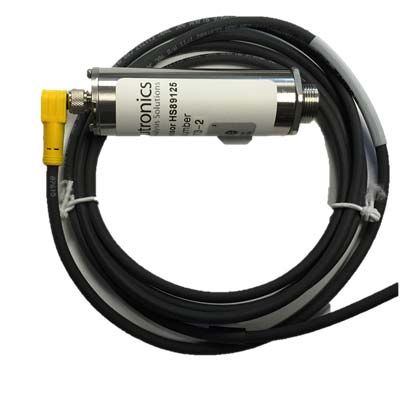
Installation and Operations Manual                                                             DTX-TC100

Safety instructions
                Installation, operation, and maintenance of the analyzer must be performed by trained
                technical personnel.
                Technical personnel must be authorized by the owner-operator to perform the tasks.
                Electrical connections must be established by a trained electrical technician.
                To prevent personal injury, technical personnel must read, understand, and follow all
                warnings and instructions in this manual before attempting installation or operation of the
                unit.
                If the operator cannot read these instructions, operating instructions and safety
                precautions must be read and discussed in the operator’s native language.
                     o Si el operador no puede leer las instrucciones, las instrucciones de operación y
                          las precauciones de seguridad deberán leerse y comentarse en el idioma nativo
                          del operador.
                     o Si l’utilisateur ne peut lire les instructions, les instructions et les consignes de
                          sécurité doivent lui être expliquées dans sa langue maternelle.
                No operator access is permitted inside the enclosure or sensor housing. Repairs not
                described in the operating instructions may only be performed by the manufacturer or the
                factory authorized service team.

Operational safety
                Follow all local standards, safety regulations, and installation guidelines. Observe proper
                safety procedures when working with pressurized gases.
                Mount the unit in a manner that will guard against excessive vibration, collapse, and
                exposure to liquids, flammable gases, flames, or high temperatures.
                Mount the unit in an area of free airflow to prevent the unit from exceeding the operating
                temperature specifications. Do not mount the analyzer or sensor against hot surfaces.
                Do not expose the Model DTX-TC100 chassis to water, high humidity or moisture. The
                analyzer chassis is not watertight.
                Do not expose the Model DTX-TC100 to flame or high temperatures.
                Do not expose the Model DTX-TC100 to flammable gases or vapors. The unit is not
                rated explosion proof or intrinsically safe.
                Ensure that the pressure of gas entering the remote sensor unit is compatible with the
                operating instructions.
                Do not expose the unit directly to an unregulated gas supply. High gas pressures may
                cause a failure in the sensor assembly.
                The unit operating voltage is: 110 VAC +/-10%, 50/60Hz, 3.5A, single phase, 3-wire.
                Failure to use the proper operating power may result in damage to the sensor assembly.
                Prior to commissioning, check that all connections are in accordance with the
                specifications listed in this manual.

Designated use
   The analyzer is a microprocessor-based instrument for measuring helium in clean gas applications. It
   is designed to minimize all effects of static discharges and interference from RFI and EMI emissions.
   If the equipment is used in a manner other than as described, the protection provided by the
   equipment may be impaired and may pose a threat to the safety of personnel.
   The manufacturer does not accept liability for damage caused by improper or non-designated use.

Manual P/N 5-06-4900-70-2                 Document No.007986                                              v
Installation and Operations Manual DTX-TC100
1 Introduction
1.1 Functional overview
The DTX-TC100 is a microprocessor-based gas analyzer designed to measure helium. The analyzer
features the Model TC100 thermal conductivity sensor. The TC100 sensor uses a thermal conductivity
gauge to measure the thermal conductivity of the gas stream and then compare it to the factory
calibration measurement.
The DTX controller is a DIN rail mounted module with analog output. A sensor interface cable connects
the remote mounted sensor to the controller.
1.2 Features
Features of the DTX-TC100 include the following:
Rapid response time – T90 < 1 second
Long service life – expected life is > 5 years
Linearized with excellent repeatability and long-term stability
Wide measurement range – measures helium from 0-100%
Robust design – the TC100 sensor is unaffected by position or motion
1.3 System hardware overview
1.3.1 DTX-TC100 controller
The DTX-TC100 controller (see Figure 1) is a 35mm DIN rail mounted module designed to provide a
gas level display and a 4-20mA loop output and to supply power to the TC100 helium sensor. It can
be mounted on a separate DIN rail or added to an existing DIN rail in any existing equipment
enclosure.
Fig. 1, analyzer enclosure
Manual P/N 5-06-4900-70-2 Document No.007986 1
DTX-TC100                                                             Installation and Operations Manual

    1.3.2 DTX-TC100 Controller inputs and outputs
    1.3.2.1 Helium sensor input

    The DTX controller communicates with the Helium sensor using a RS485 interface. Refer to Section
    2.2.3 for details on how to connect the sensor.

    1.3.2.2 Analog current output

    The analog current output is a dynamic current flow used to transmit the displayed concentration to a
    remote device during normal analyzer operation and system maintenance. The analog current
    output follows the concentration readout displayed on the DTX-TC100 controller.

    The minimum scale deflection default setting is 4mA. Full-scale is fixed at 20mA. The analog current
    output is scaled according to the selected range. Maximum electrical loading is 600 Ohms. The
    analog current output is a negative ground, non-isolated 4-20mA current loop.

    The 4-20mA loop is available on the DTX-TC100 controller pins 29 and 31.

    Refer to Section 2.2.4 for more details on how to connect the 4-20mA loop.

    1.3.3 TC100 Sensor assembly

    The sensor assembly (see Figures 2 and 3) measures the amount of helium in the gas mixture and
    transmits an electrical signal to the DTX controller. An interface cable transmits the output signal
    from the sensor at the sampling point to the DTX controller.

    The TC-100 is a thin-film thermopile thermal conductivity sensor designed with a silicon-nitride
    closed-membrane structure for high sensitivity and resolution. The measurement principle is based
    on the decrease in effective thermal resistance between the sensitive area of the sensor and the
    ambient, caused by the thermal conductance of the surrounding gas.

       Fig. 2, remote mounted sensor assembly

2                                        Document No.007986                  Manual P/N 5-06-4900-70-2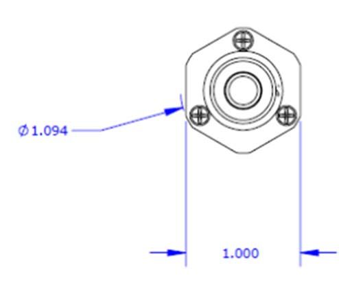
Installation and Operations Manual                                                          DTX-TC100

       Fig. 3, sensor housing, threaded connection

    1.3.4 Power supply

    A field-supplied 24VDC power supply is required to power the DTX controller which in turn supplies
    power to the TC-100 sensor.

    Neutronics Part Number 1-12-2240-09-0 is an optional DIN rail mounted single output power supply
    that features short circuit/overload/over-voltage protection and cooling by free air convection. It
    includes a built-in DC OK active signal and LED indicator for power on. Rated current output is 1A;
    rated power output is 24W. Required input voltage is 115VAC.

    1.3.5 Sensor interface cable

   The sensor interface cable (see Figure 5) provides power and communications connectivity between
   the DTX-TC100 controller and the TC100 sensor assembly. The cable includes a Turck M8 male
   right angle, 6-pin connector.

       Fig. 5, sensor interface cable with right angle 6-pin connector

Manual P/N 5-06-4900-70-2                Document No.007986                                               3
DTX-TC100                                                             Installation and Operations Manual

     1.3.6 Sensor flow-through head (optional)

    The sensor mounting base (see Figure 6) allows the TC-100 sensor to be used for process
    monitoring. It serves as both the receptacle for the sensor and the delivery system for a gas sample
    from the vessel or sample stream. It includes the sample inlet, flow-through chamber, and sample
    exhaust.

        Fig. 6, sensor mounting base

4                                        Document No.007986                  Manual P/N 5-06-4900-70-2
Installation and Operations Manual DTX-TC100
2 System installation and start-up
Step 1 Step 2 Step 3
• Install the • Make the • Power up the
components connections analyzer
Fig. 7, installation and start-up
2.1 Step 1 – Install the components
2.1.1 Locate and install DIN rail mounted controller
The controller is designed to be installed on a 35mm DIN rail. Select a suitable location for the
analyzer so that the unit can be accessed easily when necessary. The digital display, status LEDs,
and the interface buttons should be visible and unobstructed.
The analyzer is suitable for IP30 environments when properly installed. It should not be exposed to
water, adverse temperature, or shock. The analyzer should be mounted in an area with free airflow
to prevent the unit from exceeding the operating temperature specifications. Do not install the
analyzer next to hot surfaces.
DANGER: Electrical connections on the DTX-TC100 analyzer module may have
hazardous voltages present once power has been applied to the unit. High voltages
may remain present for a short time even after power has been disconnected from
the analyzer. Observe standard practices when making electrical connections.
CAUTION: The DTX-TC100 analyzer is not rated intrinsically safe or explosion proof. Be certain that
no flammable gases are present in the area where the analyzer will be installed.
WARNING: Be certain that all power is OFF to the analyzer and associated wiring (cables) before
attempting installation. DO NOT WORK WITH LIVE WIRES! Do not leave any exposed wire at the
terminal blocks. Before applying power, ensure that all wires are properly connected to the analyzer.
The terminal blocks feature screwed terminals. The pluggable terminal blocks are also removable
for ease of wiring or removal of the analyzer module.
Manual P/N 5-06-4900-70-2 Document No.007986 5DTX-TC100 Installation and Operations Manual
2.1.2 Locate and install the remote sensor assembly
The TC100 sensor assembly (see Figure 8) is designed for remote mounting. It can be installed in
the head space of an enclosure or vessel or it can be installed in ductwork or piping. The sensor
may be installed in a horizontal or vertical orientation. It includes an O-Ring seal to ensure a leak-
tight connection to the wall of the enclosure.
Viton O-ring
Fig. 8, remote sensor assembly
2.1.2.1 Flow-through head (optional)
Surface mount the flow-through head horizontally (see Figure 9) or vertically on a stationary panel.
The flow-through head is 1.25" diameter. It is machined to accommodate two #6-32 machine-type
screws (1-inch on center). Do not overtighten the mounting screws. Allow sufficient space for
installation of the sensor and the sample inlet and exhaust tube fittings.
Fig. 9, flow-through mounting head
6 Document No.007986 Manual P/N 5-06-4900-70-2Installation and Operations Manual DTX-TC100
2.2 Step 2 – Make the connections
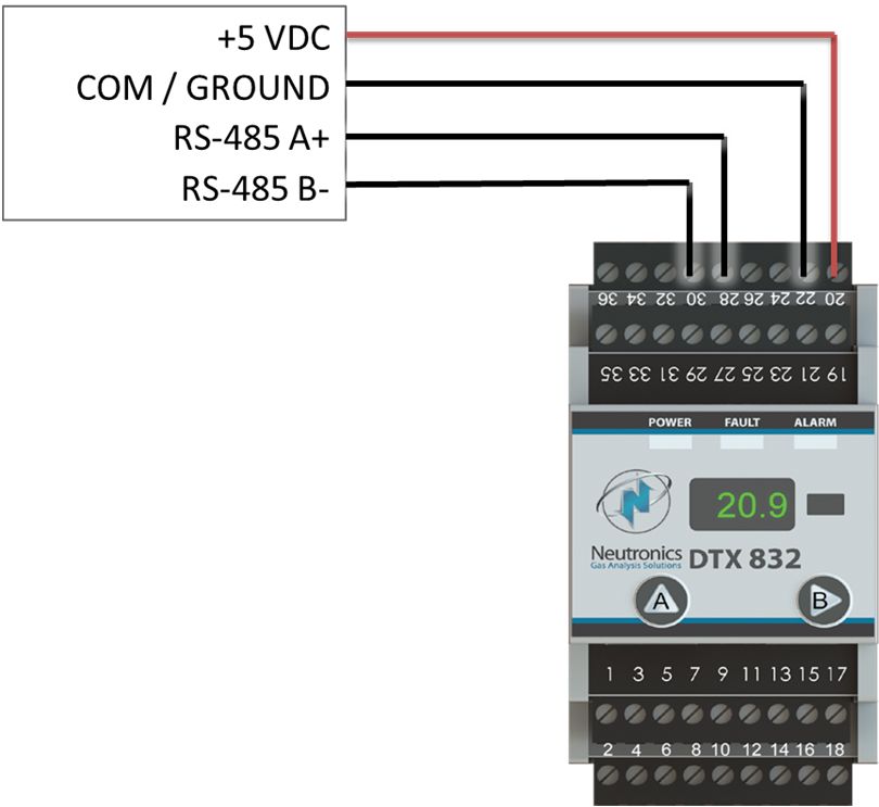
2.2.1 24 VDC power
The DTX-TC100 controller requires a field supplied 24 VDC power source. Nominal current draw for
the controller is approximately 250mA. Additional power may be required for alarm/control relays.
Use a power source that is capable of supplying a minimum of 1A or 50W to the controller.
Connect the 24 VDC power supply to the controller as shown in Figure 10.
Terminal Description
1 +24VDC in
3 Power common
22 Power common
36 +24VDC in
Fig. 10, 24 VDC power connections
Manual P/N 5-06-4900-70-2 Document No.007986 7DTX-TC100 Installation and Operations Manual
2.2.2 Helium sensor
The sensor interface cable connects the helium sensor to the DTX controller. Connect the 6-pin
locking connector to the sensor. Connect the helium sensor to the controller as shown in Figure 11.
Terminal Description
20 +5 VDC
22 Common/Ground
28 RS-485A+
30 RS-485B-
Fig. 11, sensor input
2.2.3 Analog output
The analog current output is a dynamic current flow used to communicate the displayed helium
concentration to a remote device or process control system. The analog current output follows the
concentration readout displayed on the DTX controller.
The minimum scale deflection may be set to either 0mA or 4mA. Full-scale is fixed at 20mA. The
analog current output is scaled according to the 0 to 100% measurement range. The default analog
output is 4 to 20mA. Maximum electrical loading is 600 Ohms. The analog current output is a
negative ground, non-isolated 4-20mA current loop.
8 Document No.007986 Manual P/N 5-06-4900-70-2Installation and Operations Manual DTX-TC100
Use shielded cable, 20-AWG, 2-conductor, stranded-wire, twisted pairs for the connections. The
shielded cable should be drained to earth or chassis ground at the auxiliary equipment. Connect the
DTX controller to the process control system as shown in Figure 12.
Terminal Description
29 4 to 20 mA +
31 4 to 20 mA -
Fig. 12, analog output
2.3 Step 3 – Power up the Model DTX-TC100
2.3.1 Power up check list
Verify the following conditions:
No flammable vapors are present in the area
No exposure to rain, dripping water, or hose down
Wiring installed correctly
Checked for gas-tight plumbing connection for the sensor
Ambient temperature is below 40º C (104° F)
2.3.2 Power up the unit
When the DTX-TC100 is powered-up, the LED display will first show “DTX” followed by the firmware
version.
After the startup routine is completed, the controller will display three digits with a decimal point for
percent range helium measurement.
2.3.3 Calibrate the unit
All units are calibrated at the factory prior to shipment. Field calibration is not supported in this
configuration.
Manual P/N 5-06-4900-70-2 Document No.007986 9DTX-TC100 Installation and Operations Manual
3
3.1 Basic setup
Operation
3.1.1 Configuration settings
The DTX-TC100 is shipped ready to use. Factory default configuration settings are listed in the
attached configuration report. Review the configuration settings before commissioning your system.
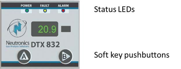
3.2 Controller user interface
3.2.2 Power indicator LED
The Power indicator LED (green) illuminates to provide local status indication that the unit is
powered up and operating (see Figure 13). When the power indicator LED is active, the unit is
measuring the concentration of the sample gas and updating the display and outputs accordingly. It
blinks on and off to indicate that the unit is functioning correctly. When a fault and an alarm are
present simultaneously, the green power indicator will turn off.
Fig. 13, controller user interface
3.2.3 Alarm indicator LED
The Alarm indicator LED (red) is not active in this configuration.
3.2.4 Fault indicator LED
The Fault indicator LED (yellow) is not active in this configuration.
3.2.5 Display
The primary purpose of the display is to show the helium concentration. It is also used for feedback
of operational status, fault codes, and other information necessary to perform system setup and
maintenance.
10 Document No.007986 Manual P/N 5-06-4900-70-2Installation and Operations Manual DTX-TC100
3.2.6 “A” pushbutton
The “A” pushbutton is used to access menus, select items, and view fault codes.
3.2.7 “B” pushbutton
The “B” pushbutton is used to access menus, run calibration, and view fault codes.
3.3 Access to the operating menus via the control panel
3.3.1 Push button operation
Short button press action is < 3 seconds.
Long button press action is > 3 seconds.
3.3.2 Network menu
Press and hold the “B” button for longer than 3 seconds to access the network menu. The
display will show “Network menu”
Use short button presses (less than 3 seconds) on the “A” button to scroll through the menu.
The display will show the current mode (static or dynamic), IP address, gateway (GW), forced
static (>), and forced dynamic (>).
If no action is taken for 20 seconds, the unit will exit the menu.
3.3.3 Option menu
Press and hold the “A” button for longer than 3 seconds. The display will show “option menu”.
Use short button presses (less than 3 seconds) on the “A” button to scroll through the menu. The
display will show the firmware version, calibration options (CAL), and reset.
If no action is taken for 20 seconds, the unit will exit the menu.
Manual P/N 5-06-4900-70-2 Document No.007986 11DTX-TC100 Installation and Operations Manual
4 Maintenance and spare parts
4.1 Routine periodic maintenance
The unit does not require any major periodic servicing. Use the chart below as a general guide.
Recommended frequency
Task At commissioning Annually As required
Clean the housing and display
4.2 Spare parts
Description Neutronics Part Number
Instruction Manual 5-06-4900-70-2
Controller module 8-32-0000-02-0
Sensor interface cable, 2m length 6-01-1001-92-2
Helium sensor assembly 8-01-1001-38-0
12 Document No.007986 Manual P/N 5-06-4900-70-2Installation and Operations Manual DTX-TC100
5 Specifications
Parameter Specification
Controller dimensions 4.16" (105.6mm) x 2.07" (52.5mm) x 2.79" (70.8mm)
Weight 1 lb. (0.45 kg)
Warm up time 1 second
Sensor type TC100, thermal conductivity
Accuracy (sensor) 0.1%
Accuracy (transmitter) 0.1% full scale
Response time T90 < 1 second
Expected sensor service life > 5 years
Controller mounting 35mm DIN rail mounting bracket
Sensor connection M16 x 1 thread
IP30 rating, no hazardous moving parts or electrical hazards. Not
Environmental
designed for dripping water.
Relative humidity 0-100%, non-condensing
Operating Temperature 0° C to 40° C (32° F to 104° F)
Storage temperature 10°C to 40°C (50°F to 104°F)
EMC EU directive 2004/108/EC
Marking (controller) CE, ETL, RoHS
Power supply (controller) 24VDC +/- 0.5V, 1.0A maximum, by field supplied PLC power supply
Power supply (TC100 sensor) 5VDC +/- 10% (from the controller)
Local display 3.7mm four character 5x7 LED dot matrix
Display resolution (controller) 0.1%
Outputs 4-20mA
Helium concentration 0 – 89.9%........XX.X
resolution 90 – 100%...... XX.X
Power (system OK) Green LED
Warranty 1 year from date of shipment
Manual P/N 5-06-4900-70-2 Document No.007986 13DTX-TC100 Installation and Operations Manual
6 Limited warranty
1. Because of the many and varied circumstances and conditions under which NEUTRONICS, INC.'s
products are used, and because NEUTRONICS, INC. has no control over this actual use,
NEUTRONICS, INC. makes no warranties which extend beyond the express provisions herein.
NEUTRONICS, INC. MAKES NO IMPLIED WARRANTIES OF MERCHANTABILITY OR FITNESS.
NEUTRONICS, INC. makes no express warranties beyond the following provisions, which only apply
to the original purchaser.
2. NEUTRONICS, INC. only warrants to the original purchaser as follows: When the products and their
component parts are properly installed and maintained in accordance with the published
NEUTRONICS, INC. manuals, and if the product has not been modified or tampered with, then only
the products actually manufactured by NEUTRONICS, INC. shall be warranted to be free from
defects in material and workmanship for a period of one year from shipment by NEUTRONICS, INC.,
except NEUTRONICS, INC. sensors which shall be free of said defects for a period of time from date
of shipment as specified in the NEUTRONICS INC. technical specifications for that specific sensor.
3. The original manufacturers' warranties apply to products and components not manufactured by
NEUTRONICS, INC.
NON-ASSIGNABILITY OF WARRANTY
4. The warranty as set forth in these terms and conditions may not be assigned, transferred, sold, or
alienated in any other way and extends only to the original purchaser.
PURCHASER'S EXCLUSIVE REMEDY
5. The original purchaser's sole and exclusive remedy, unless varied by written agreement with
NEUTRONICS, INC., is that NEUTRONICS, INC. will, at NEUTRONICS, INC.'s option, repair or
replace any defective part which is returned to NEUTRONICS, INC. within ninety (90) days of
discovery of the defect.
DISCLAIMER OF CONSEQUENTIAL DAMAGES
6. In no event shall NEUTRONICS, INC. be liable for consequential damages, including but not limited
to damages for loss of use, damages for lost profits, and damages for resulting harm to property other
than the NEUTRONICS, INC. assemblies and their component parts.
Intended use for the Model DTX-TC100
The Model DTX-TC100 helium analyzer was designed to provide the trained operator with useful
information regarding the measurement of helium in air. This information may be used for analyzing and
controlling manufacturing through timely measurements (i.e., during processing) of critical quality and
performance attributes of processes with the goal of ensuring final product quality. Before
implementation, the user must fully understand the operation and limitations of this instrument as well as
the application for its use. The responsibility for the proper application, operation, installation, and
maintenance of the Model DTX-TC100 analyzer is the sole obligation of the trained operator. The
purchaser is required to ensure that operators are properly trained in the use of this unit as well as in the
possible hazards associated with its use or with the intended application. The purchaser must ensure
that all of the proper warnings, labels, instruction manuals, lock outs, redundant components, hazard
analysis, and system validation have been completed and provided to the trained operator before
installation of the Model DTX-TC100 instrument.
Copyright © 2015, Neutronics, Inc., all rights reserved
14 Document No.007986 Manual P/N 5-06-4900-70-2You can also read