Appendix A: OPA Documents - Hydro One
←
→
Page content transcription
If your browser does not render page correctly, please read the page content below
Appendix A: OPA Documents

1                      Description of Need and Rationale for
 2                           “Oshawa Area” TS by 2015

 3   1    Summary and Purpose
 4   Pickering Generation Station (“GS”) is a critical local generation source for reliable supply of the eastern
 5   part of the Greater Toronto Area (East GTA), providing about 3,100 MW of capacity to the local area. A
 6   significant source of new transmission or generation capacity will be required to maintain reliable supply
 7   to electricity users in East GTA when Pickering GS retires.

 8   Ontario Power Generation Inc. (“OPG”), who owns and operates Pickering GS, is considering extending
 9   the life of the nuclear station to 2020 however, there is a possibility it could be completely out of service
10   by early 2015. The reliability consequence of Pickering GS retiring by 2015, without a new source of
11   capacity in place, is the loss of about 750 MW of load within the East GTA, following a single contingency
12   event. This level of load loss for a single contingency event is 5 times higher than the current planning
13   criteria allows for planning transmission facilities in Ontario.

14   Installation of a new 500‐230 kV Transformer Station (“TS”) called “Oshawa Area” TS is the only feasible
15   solution to address retirement of Pickering GS and to mitigate the risk of early retirement. The solution
16   was also outlined in the Ontario Power Authority (“OPA”) ‐ 2011 IPSP Planning and Consultation
17   Overview document dated May 2011 (pages 5‐11)

18   http://www.powerauthority.on.ca/sites/default/files/page/IPSP%20Planning%20and%20Consultation%
19   20Overview.pdf as well as in the Transmission Planning component of the IPSP 2011 Stakeholder
20   Consultation Presentation (slides 38 and 39)
21   http://www.powerauthority.on.ca/sites/default/files/page/Transmission%20Presentation.pdf.

22   “Oshawa Area” TS also includes new switching facilities that provide improved load restoration
23   capabilities to the Pickering, Ajax, Oshawa and Clarington areas. Existing supply facilities serving these
24   areas are not capable of meeting existing load restoration requirements specified within the Ontario
25   Resources and Transmission Assessment Criteria (“ORTAC”) document issued by the Independent
26   Electricity System Operator (“IESO”). “Oshawa Area” TS would enable meeting the requirements
27   specified in ORTAC.

28   Since there is some risk of inadequate supply by as early as 2015, the OPA believes that it is prudent to
29   prepare for implementing “Oshawa Area” TS by the 2015 date for the following reasons:

30       1. The consequence of not being prepared would expose customers in the eastern portion of the
31          GTA to an unacceptable level of risk to reliability by 2015 (exposure to about 750 MW of load
32          rejection for a single contingency event).
33       2. Transmission facilities currently serving the Pickering, Ajax, Oshawa and Clarington areas are not
34          currently capable of meeting load restoration criteria specified in ORTAC. “Oshawa Area” TS
35          provides facilities which rectify this situation.
                                                                                                             1
                                                         Ontario Power Authority
           120 Adelaide Street West, Ste. 1600, Toronto, Ontario M5H 1T1 Tel 416 967‐7474 Fax 416 967‐1947 Toll Free 1‐800‐797‐9604
                                             info@powerauthority.on.ca www.powerauthority.on.ca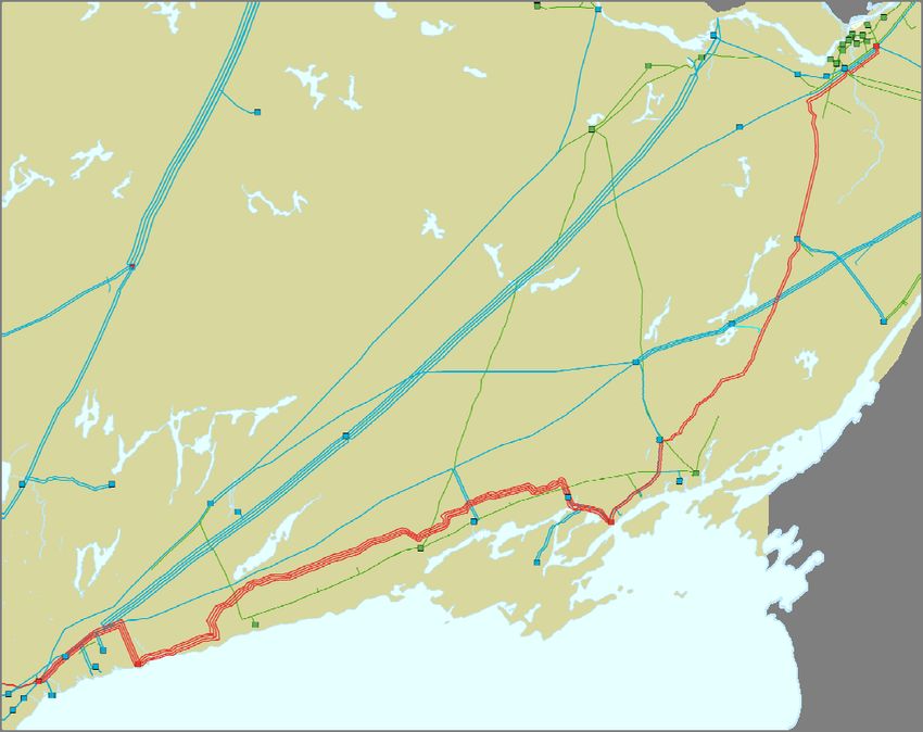
1       3. “Oshawa Area” TS is also the recommended solution for the scenario where the operation of
 2          Pickering GS is extended to 2020. The cost impact of installing “Oshawa Area” TS in 2015 as
 3          opposed to installing the station in 2020 is $60 million. It is necessary to make expenditures
 4          now to mitigate the reliability risks mentioned above given that a decision on the retirement
 5          date of Pickering GS is still forthcoming.

 6   To provide for the timely implementation of this recommended solution the OPA has requested that
 7   Hydro One develop a flexible implementation plan. This implementation plan should be designed to
 8   ensure that the 2015 in service date can be met to mitigate the risk to reliability should Pickering retire
 9   in 2015, while at the same time providing appropriate technical and commercial off‐ramps, to minimize
10   cost exposure should it be confirmed by OPG that at least 2 units will be available at Pickering beyond
11   the 2015 date and there is an opportunity to defer some expenditures for this project. Two letters from
12   the OPA to Hydro One on this subject are attached in Appendix 1.

13   The purpose of this document is to update the analysis that considered viable alternatives and provide
14   the rationale for the recommended solution to address the retirement of Pickering GS.

15   2 System Needs
16   2.1 Supply sources for East GTA 230 kV system

17   Pickering GS, which includes six units with total output capacity of 3,100 MW, is a critical local
18   generation source for supplying East GTA. Pickering GS reduces the required power transfers from the
19   500 kV bulk transmission system through the 500‐230 kV autotransformers at Cherrywood TS (with four
20   autotransformers) and Parkway TS (with two autotransformers).

21   Information received from Ontario Power Generation Inc., who owns and operates Pickering GS,
22   indicates that there is a possibility that Pickering GS could be shut down completely by early 2015. OPG
23   is considering options to extend the operating life of Pickering GS to the year 2020. The extended
24   operation is not a certainty as it is dependent on the successful outcome of studies to confirm the
25   technical feasibility and obtaining the necessary approvals. The results of these studies and receipt of
26   approvals are not expected to be known before the latter part of this year or possibly next year.

27   System studies performed for the Ontario Power Authority by the IESO indicated that a minimum of
28   two Pickering units are required to be in service to maintain reliable supply for the area during peak load
29   periods. The existing six 500‐230 kV autotransformers at Cherrywood TS and Parkway TS would not
30   have sufficient capacity to supply the load in East GTA reliably with less than two Pickering GS units in
31   operation.

32   The studies further indicated that, with no Pickering units in‐service, loss of one of the four 500‐230 kV
33   autotransformers at Cherrywood TS would result in a serious overload on one of the three remaining
34   autotransformers at Cherrywood TS. Load interruptions of about 750 MW would be required to reduce

                                                                                                                                      2
                                                         Ontario Power Authority
           120 Adelaide Street West, Ste. 1600, Toronto, Ontario M5H 1T1 Tel 416 967‐7474 Fax 416 967‐1947 Toll Free 1‐800‐797‐9604
                                             info@powerauthority.on.ca www.powerauthority.on.ca
1    the loading on the overloaded transformer to be within its equipment rating. This level of load loss is
2    five times higher than the current planning criteria allows for planning transmission facilities in Ontario.

 3   Given the above circumstances, OPA believes that there is a possibility that the electricity users in East
 4   GTA cannot be supplied reliably in 2015. A solution is therefore required to mitigate this risk.

 5   Even if the operating life of Pickering GS is extended, the solution to address Cherrywood TS 500‐230 kV
 6   autotransformer overloads is required by no later than year 2020 when Pickering GS would be retired.
 7   In addition to the above mentioned need, Pickering GS also provides approximately 1,000 MVar of
 8   reactive power to support the East GTA area system voltages. In the absence of Pickering GS, an
 9   alternate source for this reactive power would also be required.

10   2.2 Supply Reliability Needs of Pickering, Ajax, Oshawa and Clarington Areas

11    The 230 kV step‐down stations supplying Local Distribution Company loads east of Cherrywood TS (in
12   Pickering, Ajax, Oshawa and Clarington areas) are supplied by long 230 kV circuits emanating eastward
13   from Cherrywood TS. The total load supplied in this area is forecast to be about 750 MW with about
14   300 MW supplied by H24C and H26C circuits and about 450 MW supplied by M29C and B23C circuits.
15   These circuits are on a four circuit transmission line. The terminal stations to the east are far from the
16   area, as shown in Figure 1 below.

17   In the event of a permanent fault affecting either of these pair of circuits, it would not be possible to
18   supply load from the eastern end of these circuits due to the long distance involved. The existing
19   transmission facilities supplying the loads in this area are inadequate for the purpose of meeting the
20   IESO’s load restoration criteria under ORTAC. New transmission or generation facilities are required to
21   provide the required reliable supply.

                                                                                                                                      3
                                                         Ontario Power Authority
           120 Adelaide Street West, Ste. 1600, Toronto, Ontario M5H 1T1 Tel 416 967‐7474 Fax 416 967‐1947 Toll Free 1‐800‐797‐9604
                                             info@powerauthority.on.ca www.powerauthority.on.ca
Figure 1: Terminal stations for transmission circuits supplying Pickering, Ajax, Oshawa and Clarington

                                                                          Chats Falls SS:
                                                                          C28C
                                                                          Termination

                                                                                                                    Merivale TS:
                                                                                                                    M29C
                                                                                                                    Termination

                          Havelock TS:
                          H24C, H26C
                          Termination

      Cherrywood TS
                                                                                     Belleville TS:
                                                                                     B23C
                                                                                     Termination

                                    Step‐down stations for Pickering, Ajax, Oshawa and Clarington

    Source: OPA
1

2   2.3 New Generation at Darlington

3   Ontario’s Long‐Term Energy Plan indicates that new nuclear generation totalling up to 2,000 MW at
4   Darlington will be needed by the early 2020’s. Therefore, any alternatives that would meet the above
5   mentioned needs must also be compatible with the facilities required for the incorporation of new
6   nuclear units at Darlington GS. Previous system studies indicated that a new double circuit 500 kV
7   transmission line between Darlington GS and Cherrywood TS would be required for the incorporation of
8   new nuclear units at Darlington.

                                                                                                                                     4
                                                        Ontario Power Authority
          120 Adelaide Street West, Ste. 1600, Toronto, Ontario M5H 1T1 Tel 416 967‐7474 Fax 416 967‐1947 Toll Free 1‐800‐797‐9604
                                            info@powerauthority.on.ca www.powerauthority.on.ca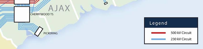
1 3 Alternative Solutions
2 3.1 Generation Alternatives
3 Installing new generation totaling 1,000 MW close to Cherrywood TS would be necessary to meet the
4 required supply reliability in East GTA. The planning criteria within ORTAC requires that this 1,000 MW
5 be comprised of at least two generating units (500 MW each), or a number of smaller units within the
6 area. This multiple generating unit requirement provides the diversity needed to ensure supply
7 reliability. To meet the need, these generation facilities are required to be installed prior to spring 2015,
8 to address the early retirement of Pickering GS. There has been interest for generation projects in the
9 area through the OPA’s ‐ Combined Heat & Power (“CHP”) procurement program. However, the total
10 amount of interest is about 300 MW and it is not sufficient to meet the need even if they could be
11 installed by March 2015. The OPA has other generation procurement programs such as FIT, microFIT
12 and CESOP with interest in the area, but the total amount would not be sufficient to meet the need,
13 even when combined with the CHP interest.
14 Given that it will take longer than the 2015 need date to incorporate a sufficient amount of new
15 generation in this area, the generation option has been determined to be infeasible.
16 3.2 Transmission Alternatives
17 Alternative 1: “Oshawa Area” 500‐230 kV TS (the recommended solution)
18 Hydro One owns a property at the border of Oshawa and Clarington, north of Winchester Road /
19 Concession 7 between Grandview Street and Enfield Road. This is a location where the 500 kV lines and
20 the 230 kV lines in the area converge, and it has been planned for installation of 500‐230 kV
21 autotransformers and switching facilities for the long 230 kV circuits in the area. Figure 2 below shows
22 the location of “Oshawa Area” TS. The following is a high level description of this alternative.
23 At “Oshawa Area” TS install:
24 Two 500‐230 kV, 750 MVA auto‐transformers each connecting to one of the four 500 kV
25 Bowmanville to Cherrywood circuits using 500 kV circuit breakers;
26 Switching facilities for the existing five long 230 kV circuits emanating east from
27 Cherrywood TS; and
28 Two 230 kV ‐ 150 MVAR shunt capacitor bank.
29
30 At Cherrywood TS install:
31 Two 230 kV ‐ 300 MVAR shunt capacitor banks.
32 This option would meet the 500‐230 kV autotransformer capacity and reactive power requirements
33 outlined in Section 2.1, as well as the regional supply reliability needs of the area.
34 In addition to meeting the required needs, this alternative provides the following additional benefits:
5
Ontario Power Authority
120 Adelaide Street West, Ste. 1600, Toronto, Ontario M5H 1T1 Tel 416 967‐7474 Fax 416 967‐1947 Toll Free 1‐800‐797‐9604
info@powerauthority.on.ca www.powerauthority.on.ca1 The new transformer station would provide a new load supply point in an area where
2 growth is expected. This would reduce the reliance on Cherrywood TS as the only major
3 supply source for the East GTA.
4 A new 500 kV double circuit line from Bowmanville SS (Darlington) west ward towards the
5 GTA is expected to be required for incorporation of Darlington B units. The “Oshawa Area”
6 TS would obviate the need for a 27 km line section between Cherrywood TS and “Oshawa
7 Area” TS. In addition, two circuits from the new 500 kV line between Bowmanville SS and
8 “Oshawa Area” TS would not require additional 500 kV circuit breakers at “Oshawa Area”
9 TS, whereas additional 500 kV breakers would be needed if these lines terminated at
10 Cherrywood TS.
Figure 2: Oshawa Area TS
Source: OPA
11
12 Alternative 2: Expand Cherrywood TS
13 There are four 500‐230 kV autotransformers at Cherrywood TS, which are connected to two separate
14 230 kV switchyards. These two switchyards are not interconnected due to the fact that this connection
15 arrangement would exceed the short circuit levels of the major equipment. Studies conducted by the
16 IESO, at the OPA’s request, have confirmed that, given this connection arrangement, installing two
17 additional 500‐230 kV autotransformers at Cherrywood does not help to alleviate the potential overload
18 situation under the criteria specified within ORTAC. The IESO studies indicate that the two switchyards
19 would need to be interconnected to be effective. Since the interconnection of the 230 kV switchyards
20 would result in short circuit levels beyond the capabilities of the existing 230 kV breakers, even when all
21 Pickering units are retired, this option is considered infeasible. The short circuit level would also be
22 higher than the capability of new 230 kV breakers even if the existing breakers could be replaced in
23 time.
6
Ontario Power Authority
120 Adelaide Street West, Ste. 1600, Toronto, Ontario M5H 1T1 Tel 416 967‐7474 Fax 416 967‐1947 Toll Free 1‐800‐797‐9604
info@powerauthority.on.ca www.powerauthority.on.ca1 In addition, the above facilities also do not address the regional supply reliability needs of Pickering,
2 Ajax, Oshawa and Clarington areas, outlined in Section 2.2. Four new transmissions circuits extending
3 east from Cherrywood TS would still be required to address the area supply reliability needs.
4 Alternative 3: Expand Parkway TS
5 Parkway 500‐230 kV TS is located west of Cherrywood TS. There are currently two 500‐230 kV
6 autotransformers at Parkway TS. IESO studies, conducted at the request of the OPA, have confirmed
7 that installing two additional 500‐230 kV autotransformers at Parkway TS would not provide sufficient
8 reduction on the autotransformers at Cherrywood TS. Options were investigated to determine if
9 another solution could be found for reducing the loading on the Cherrywood 500‐230 kV
10 autotransformers, given the significant impact (the loss of 3,100 MW of local generation within the East
11 GTA) when Pickering retires. It was found that the installation of four new 230 kV circuits connecting
12 Parkway TS to the existing 230 kV circuits between Richview TS and Cherrywood TS, on the Finch
13 transmission corridor, would be necessary to achieve the required loading relief on the 500‐230 kV
14 autotransformers at Cherrywood TS.
15 This alternative was determined to be infeasible from an implementation perspective for the following
16 reasons:
17 The area where the four 230 kV circuits connections are to be located has been fully developed
18 for a number of years, as shown in Figure 3. It would be very difficult to obtain a new right of
19 way or expand the existing right of way for the four new 230 kV circuits. There is a significant
20 risk of not being able to obtain the necessary right of way in a timely manner.
21 IESO studies indicate the improvement in the supply capability provided by this alternative is
22 significantly inferior to that from “Oshawa Area” TS.
23 In addition, the above facilities also do not address the regional supply reliability needs of Pickering,
24 Ajax, Oshawa and Clarington areas, outlined in Section 2.2. Four new transmission circuits extending
25 east from Cherrywood TS would still be required to address the area supply reliability needs.
26 Therefore, this option is not considered further.
7
Ontario Power Authority
120 Adelaide Street West, Ste. 1600, Toronto, Ontario M5H 1T1 Tel 416 967‐7474 Fax 416 967‐1947 Toll Free 1‐800‐797‐9604
info@powerauthority.on.ca www.powerauthority.on.caFigure 3: Parkway TS and Finch 230 kV transmission line between Richview TS and Cherrywood TS
Parkway TS
Richview x Cherrywood
230 kV circuits
Source: OPA
1
2 4 Conclusion
3 The transmission Alternative 1 (installation of “Oshawa Area” 500‐230 kV TS) is the recommended
4 alternative because it is the only alternative that meets all of the identified needs and can be
5 implemented in time to address the risk of early retirement of Pickering GS. Implementation of
6 “Oshawa Area” TS by 2015 represents an advancement of the project which would be required by 2020
7 assuming OPG is successful in extending the life Pickering GS.
8
Ontario Power Authority
120 Adelaide Street West, Ste. 1600, Toronto, Ontario M5H 1T1 Tel 416 967‐7474 Fax 416 967‐1947 Toll Free 1‐800‐797‐9604
info@powerauthority.on.ca www.powerauthority.on.caAppendix 1 - Description of Need and Rationale for "Oshawa Area" TS by 2015 (May 2012) / Page 1 of 8
Appendix 1 - Description of Need and Rationale for "Oshawa Area" TS by 2015 (May 2012) / Page 2 of 8
Appendix 1 - Description of Need and Rationale for "Oshawa Area" TS by 2015 (May 2012) / Page 3 of 8
Appendix 1 - Description of Need and Rationale for "Oshawa Area" TS by 2015 (May 2012) / Page 4 of 8
Appendix 1 - Description of Need and Rationale for "Oshawa Area" TS by 2015 (May 2012) / Page 5 of 8
Appendix 1 - Description of Need and Rationale for "Oshawa Area" TS by 2015 (May 2012) / Page 6 of 8
Appendix 1 - Description of Need and Rationale for "Oshawa Area" TS by 2015 (May 2012) / Page 7 of 8
Appendix 1 - Description of Need and Rationale for "Oshawa Area" TS by 2015 (May 2012) / Page 8 of 8
EB-2007-0707
                                                                            Exhibit E
                                                                            Tab 4
                                                                            Schedule 1
                                                                            Page 1 of 15
                                                                            Plus Appendix A

 1                          OSHAWA AREA TRANSFORMER STATION

 2   1.0    EXECUTIVE SUMMARY

 3   The purpose of this project is to address the potential impact associated with the retirement
 4   or refurbishment of the Pickering B generating station. It also addresses potential regional
 5   supply needs and the long term potential to incorporate new generation at Darlington.

 6   Pickering B provides important load supply to the eastern half of the Greater Toronto
 7   Area (“GTA”) and provides significant voltage support to the GTA system. Pickering B also
 8   reduces loading on the 500/230 kV transformers at Cherrywood. If a decision is made to
 9   retire Pickering B, then there will likely be a need for additional transformation capacity by
10   2015. Additional reactive power facilities, such as a Static Var Compensator (“SVC”) and
11   shunt capacitor banks, would also be required. Alternatively, if a decision is made to
12   refurbish Pickering B, and more than two Pickering B units are removed from service at a
13   time, there will also be a need for replacement capacity in 2015. A new Oshawa
14   transformer station will address the loss of supply capacity resulting from the retirement of
15   Pickering B or mitigate an unfavourable refurbishment schedule.

16   A new Oshawa transformer station will also provide flexibility to meet potential growing
17   supply needs in the eastern GTA and to accommodate potential new generation at
18   Darlington GS in the longer term.

19   It is necessary to commence transmission development work in 2009 in order to meet the
20   potential need date of 2015 which may be triggered by a decision to retire Pickering B or
21   confirmation of an unfavourable refurbishment schedule where more than two Pickering B
22   units are unavailable for an extended period. This development work should also start in
23   2009 if the retirement decision is delayed. This development work can subsequently be
24   deferred or discontinued if the decision is made to refurbish Pickering B and the
25   refurbishment schedule is favourable.
EB-2007-0707
Exhibit E
Tab 4
Schedule 1
Page 2 of 15
Plus Appendix A
1 The development work will include technical system studies, preliminary engineering,
2 preparation and seeking of approval of environmental assessment (“EA”) terms of
3 reference and seeking EA approval. The estimated cost of development work is
4 $1.5 million, approximately 1% of the total project cost estimated at $170 million.
5 2.0 DESCRIPTION OF EXISTING AND EXPECTED FACILITIES
6 For the purpose of this evidence, the Town of Ajax, the City of Oshawa, the City of
7 Pickering and the Town of Whitby are collectively referred to as GTA East. The existing
8 power system facilities in GTA East include:
9 1. The Pickering A Generation Station (“Pickering A”) has two 515 MW generating units for
10 a combined output of approximately 1,030 MW. At Pickering B Generation Station
11 (“Pickering B”) there are four 516 MW generating units for a combined output of
12 approximately 2,064 MW.
13 2. One cogeneration facility, Whitby Cogen, connects to circuit H26C. This is a 50 MW
14 gas-fired cogeneration facility.
15 3. The Cherrywood Transformer Station (“Cherrywood”) is the major transmission station
16 that connects the 500 kV network to the 230 kV system via four 500/230 kV
17 transformers. Pickering A and Pickering B generation (together known as “Pickering
18 Generation”) is connected to the 230 kV system at Cherrywood.
19 4. To the east, two double-circuit 500 kV lines connect Cherrywood to the Bowmanville
20 Transformer Station (“Bowmanville”) and to the west, two double-circuit 500 kV lines
21 connect Cherrywood TS to the Parkway Transformer Station (“Parkway”).
22 5. Five 230 kV circuits emanating east from Cherrywood provide local supply to the area.
23 These lines range in length from 124 km to 302 km, and extend from Cherrywood in the
24 City of Pickering to eastern Ontario. Two of these circuits (M29C and C28C) terminate
25 at Ottawa, two at Havelock (H24C and H26C), and one at Belleville (B23C).
26
27 An electrical schematic of the GTA East and neighbouring transmission facilities is shown
28 in Appendix A.EB-2007-0707
Exhibit E
Tab 4
Schedule 1
Page 3 of 15
Plus Appendix A
1 3.0 NEEDS ANALYSIS
2 3.1 Operation of Cherrywood
3 Cherrywood is a key 500 kV station that connects the 500 kV system in eastern Ontario
4 with the rest of the 500 kV system in the GTA and beyond. Generation and imports from
5 eastern Ontario flow to the GTA primarily on the 500 kV network at Cherrywood. A
6 significant portion of that power is delivered to the 230 kV network via the Cherrywood
7 500/230 kV transformers to service the load in GTA East as well as the eastern portion of
8 Toronto and the Markham areas. The combined load in these areas is much greater than
9 the capability of the Cherrywood transformers and must rely on supply from Pickering
10 Generation. Lower levels of Pickering Generation result in higher flows on the Cherrywood
11 transformers.
12 At the 230 kV level, there are two physically separate switchyards that connect the 230 kV
13 circuits at Cherrywood. Each switchyard must be electrically split when there are more
14 than four Pickering Generation units connected to maintain short circuit levels within
15 equipment ratings. In such configurations, there are effectively four smaller switchyards or
16 “bus quarters”. This mode of operation is referred to as “quarter mode.” There is one
17 500/230 kV transformer connected to each bus quarter. When there are more than four
18 Pickering Generation units connected, some bus quarters will have two units connected
19 and others will have only one unit. Under these situations, the flow on the 500/230 kV
20 transformers will not be balanced. The bus quarters with only one unit connected will have
21 a higher flow than the ones with two units. The overall transformation capability will be
22 limited by the transformers with the highest flow.
23 3.2 Pickering B Refurbishment or Retirement
24 As discussed in Exhibit D-9-1 (Meeting Resource Requirements), Ontario Power
25 Generation (“OPG”) is in the process of assessing the prospect of refurbishing the four
26 Pickering B units. Results of the assessment will not be known until 2008. In view of the
27 uncertainty of the outcome, the transmission impacts of both refurbishment and retirementEB-2007-0707
Exhibit E
Tab 4
Schedule 1
Page 4 of 15
Plus Appendix A
1 of Pickering B are considered. Under OPG’s preliminary schedule for refurbishment, units
2 will be taken out of service for refurbishment beginning in 2013. Over a three-year period
3 beginning in 2015, up to two units may be out of service at a time. Under OPG’s
4 preliminary retirement schedule, two units will be retired by the end of 2014 and all
5 Pickering B units will be retired by the end of 2016.
6 3.2.1 Assessment of Pickering B Refurbishment
7 The IESO performed an analysis of the impact of two and three Pickering B units taken out
8 of service for 2015 summer peak conditions. Further details of the analysis methodology
9 and study assumptions can be found in the IESO report entitled “IESO Preliminary
10 Assessment Report: Nuclear scenarios in the GTA East”. This report is included as
11 Attachment 1 to this exhibit. The analysis looked at outage scenarios which resulted in
12 balanced and unbalanced flows on the 500/230 kV transformers at Cherrywood. These
13 results are summarized in Table 1 below:
14 Table 1: 2015 Cherrywood Transformer Flows with Pickering B Outages
Cherrywood Continuous # of Pickering B units in-service
Transformer Rating (MVA) 2 (Balanced Scenario) 2 (Unbalanced Scenario) 1
T14 750 677 755 779
T15 750 664 583 685
T16 750 667 586 689
T17 750 668 745 768
Source: IESO
15
16 The results show that for two units out of service in an unbalanced scenario, T14 would be
17 just over its continuous rating. With three units out of service or just one unit in service,
18 both T14 and T17 are over their continuous rating. This analysis does not include the
19 effects of Conservation programs. With the estimated levels of Conservation in the GTA by
20 2015 and the resulting lower load levels, the Cherrywood transformer ratings would not be
21 exceeded for any two units out of service.EB-2007-0707
Exhibit E
Tab 4
Schedule 1
Page 5 of 15
Plus Appendix A
1 The OPA performed an additional assessment on the scenario with three units out of
2 service and varying levels of Conservation. These results are summarized in Table 2
3 below:
4 Table 2: 2015 Cherrywood Transformer flows with 3 Pickering B units out
Cherrywood Continuous Level of GTA Conservation
Transformer Rating (MVA) 100% 60% 0%
T14 750 726 757 778.9
T15 750 630 659 685.4
T16 750 633 662 688.5
T17 750 716 747 768.2
Source: OPA and IESO
5
6 The OPA found that for the full estimated level of Conservation the flows are within the
7 ratings of the Cherrywood transformers. At conservation levels of 60% or less, the
8 transformer ratings would be exceeded for 2015 loading conditions. Given the importance
9 of Cherrywood to supply the GTA East and eastern Toronto area loads, additional relief for
10 the Cherrywood transformers needs to be planned to take into account uncertainties
11 associated with load forecasts and Conservation estimates.
12 3.2.2 Assessment of Pickering B Retirement
13 As illustrated in Attachment 1, the IESO conducted an analysis with all four Pickering B
14 units retired. The analysis also looked at the 2015 summer peak conditions given that the
15 last Pickering B unit may be retired in 2016. These are complex and aging units. It would
16 not be prudent to time transmission reinforcements that may require significant lead time
17 too close to estimated retirement dates. The results with Pickering B retired are shown in
18 Table 3:
19 Table 3: 2015 Cherrywood Transformer flows with Pickering B retired
Cherrywood Continuous Rating Flow
Transformer (MVA) (MVA)
T14 750 831
T15 750 903
T16 750 907
T17 750 819
Source: IESO
20EB-2007-0707
Exhibit E
Tab 4
Schedule 1
Page 6 of 15
Plus Appendix A
1 The results show that all the Cherrywood transformer ratings would be significantly
2 exceeded. After applying the full level of Conservation, these facilities would still be
3 significantly exceeded. It should be noted that this analysis was performed with one
4 Pickering A unit unavailable. In accordance with the “study parameters and contingency
5 criteria” of the IESO Ontario Resource and Transmission Assessment Criteria (the “IESO
6 ORTAC”), the analysis must consider up to two local generators unavailable with all
7 transmission elements in service. Once the Pickering B units are permanently unavailable,
8 then the system must be planned with the consideration that Pickering A units could be
9 unavailable for extended maintenance or unforeseen problems. The analysis with the
10 refurbishment scenario was performed with both Pickering A units available. This assumed
11 that extended maintenance of the Pickering A units would, prudently, not be scheduled
12 during summer months while two or more Pickering B units were out for major
13 refurbishment.
14 Based on this analysis, additional facilities to relieve the Cherrywood transformers will be
15 required by 2015 should Pickering B be retired.
16 3.3 Other Considerations
17 3.3.1 GTA Voltage Support
18 The Pickering B generation can provide approximately 1,000 MVar of reactive power to
19 support the GTA system voltage. The reactive power provided by generators is “dynamic”
20 and is more effective than reactive power provided by “static” shunt capacitor banks.
21 Generators and their excitation systems have the ability to maintain reactive power that is
22 insensitive to voltage changes over a wide operating range. Shunt capacitor banks are
23 sensitive to the system voltage. When the system voltage is declining as a result of
24 disturbances, shunt capacitors provide less reactive power at a time when they are needed
25 most.
26 Without Pickering B, not only would this amount of reactive power be unavailable but also,
27 the additional power flow needed to replace the 2,000 MW into the GTA transmissionCorrected: October 19, 2007
EB-2007-0707
EB-2007-0707
Exhibit
ExhibitEE
Tab
Tab44
Schedule
Schedule11
Page
Page77ofof15
15
Plus
PlusAppendix
AppendixAA
1 system would create additional reactive power consumption in the GTA. At a minimum,
2 facilities to provide 250 Mvar of dynamic reactive power and 750 Mvar of shunt capacitors
3 are needed if Pickering B is retired. Additional reactive power facilities may be required
4 depending on future system conditions and the new facilities that are installed to address
5 the supply capacity issues. This will require further studies and development work. As
6 illustrated in Attachment 1 (IESO’s analysis in Section 4.0) 1,000 MVar of additional
7 reactive power was included in the options.
8 Assuming that the 250 Mvar of dynamic reactive power is provided by such devices as an
9 SVC, and the balance of the reactive power is provided by shunt capacitors, the OPA
10 estimates that reactive replacement facilities could cost in the range of $50 million.
11 3.3.2 New Generation at Darlington
12 In Exhibit D-6-1 (Nuclear Resources for Baseload), new baseload generation resources are
13 expected to be in-service beginning as early as 2018. A possible scenario is that new
14 baseload generation of up to 1,500 MW could be built at the Darlington site and connected
15 to the Bowmanville Station. Beginning also in 2018, Darlington units are expected to be
16 taken out for major refurbishment based on OPG’s preliminary refurbishment schedule.
17 Therefore, while new units may be brought into service, existing Darlington units may be
18 taken out of service at the same time. As a result, there may not be a net increase of
19 generation at Darlington until 2022.
20 Adding 1,500 MW of additional generation at Darlington will require increased capacity on
21 the 500 kV circuits from Bowmanville to Cherrywood. These circuits presently have room
22 for approximately 1,500 MW additional power flow from Bowmanville. But with potential
23 imports from the new 1,250 MW interconnection with Québec, and 200 to 300 MW of
24 additional generation from various procurement initiatives (RES, CESOP, etc.) expected in
25 eastern Ontario in the next few years, this remaining capacity would be fully utilized.Corrected:
EB-2007-0707 October 19, 2007
EB-2007-0707
Exhibit E
Exhibit
Tab 4 E
Tab 4
Schedule 1
Schedule
Page 8 of115
Page 8 of 15 A
Plus Appendix
Plus Appendix A
1 3.3.3 Regional Supply Capacity
2 In the longer term, additional supply capacity for GTA East may be required. Historically
3 the load has been growing at an average annual rate of approximately 4.2% over the last
4 five years. Load forecast data received from the LDCs show an area growth rate of 1.8%
5 over the next 10 years. It is assumed that the load from directly connected large industrial
6 customers in the area is unchanged from 2006 levels.
7 Based on a 1.8% growth rate, additional facilities to increase supply capacity and permit
8 new stations to connect to the five 230 kV circuits serving the area may be needed by
9 2014. With the expected Conservation resources of 128 MW by 2014 and 234 MW by
10 2027, additional capacity may not be required until 2020 or beyond, even with load forecast
11 and Conservation estimates uncertainties considered.
12 Following the connection of the new Enfield load station in Oshawa, the installed load
13 station capacity connected to the five supply circuits will either be at the circuit capacity or
14 be very close to the 600 MW limit for a double-circuit line supply. The load security criteria
15 specified in the IESO ORTAC does not permit a load loss greater than 600 MW for a
16 double-circuit line loss.
17 Beyond 2020, to connect new load stations requires either new circuits from Cherrywood or
18 a new supply point that can permit the existing circuits to be sectionalized and reduce the
19 load connected on any two circuits. With the existing system, the five circuits from
20 Cherrywood are long lines with most of the load support coming from the Cherrywood end
21 rather than from Ottawa, Havelock or Belleville. Sectionalizing the existing lines without a
22 new supply point would be ineffective. The remote ends at Ottawa, Havelock or Belleville
23 are unable to support the load should the circuits be opened at Cherrywood. A new supply
24 point such as the Oshawa Area Transformer Station with a 230 kV switchyard would
25 sectionalize all five circuits and permit additional load stations to be connected in GTA East
26 without the need for additional circuits. This option is described in Section 4.1 below.EB-2007-0707
Exhibit E
Tab 4
Schedule 1
Page 9 of 15
Plus Appendix A
1 4.0 DEVELOPMENT OF ALTERNATIVES
2 The following three alternatives address the need to relieve the Cherrywood transformers
3 under the following conditions: 1) Pickering B is not refurbished; or 2) the refurbishment of
4 Pickering B requires more than two units to be out of service for extended refurbishment
5 periods.
6 4.1 Alternative #1: Oshawa Area Transformer Station
7 4.1.1 Relief for the Cherrywood Transformers
8 A new Oshawa transformer station would provide new supply to GTA East and reduce the
9 power flows through 500/230 kV transformers at Cherrywood. This alternative would
10 provide GTA East with two supply points: Cherrywood Station in the west, and Oshawa
11 Area Station in the east. A conceptual illustration of this project is shown in Figure 1.
12 Figure 1: Oshawa Area Transformer Station
Source: OPAEB-2007-0707
Exhibit E
Tab 4
Schedule 1
Page 10 of 15
Plus Appendix A
1 Building a transformer station at this site will relieve the transformers at Cherrywood if
2 Pickering B is not refurbished. The calculated flows on the Cherrywood and Oshawa Area
3 transformers under 2015 peak demand periods without Pickering B are shown in Table 4.
4 Table 4: Transformer Loadings in Alternative #1
Transformer Continuous Transformer Flow
Rating (MVA) (MVA)
Cherrywood T14 750 706.4
Cherrywood T15 750 745.7
Cherrywood T16 750 749.1
Cherrywood T17 750 696.5
Oshawa T1 (new) 750 514.8
Oshawa T2 (new) 750 513.9
Source: IESO
5
6 As shown in Table 4, above, the power flow on each of the transformers remains below
7 their continuous ratings, though power flows on Cherrywood transformers T15 and T16 are
8 near their continuous rating. This analysis does not include Conservation. It is expected
9 that the estimated Conservation levels will reduce the amount of load supplied by these
10 stations so additional supply capacity may not be required until the longer term. The
11 uncertainty of estimating conservation resources in regional and local areas is discussed
12 further in Exhibit E-2-3 Integrating Conservation. As experience is gained with
13 Conservation resources in GTA and the GTA East in particular, the need for further
14 500/230 kV transformation capacity in GTA East can be refined.
15 4.1.2 Other Considerations
16 The incorporation of new generation at Darlington would require a new 500 kV transmission
17 line between the Bowmanville Transformer Station and the GTA. The Oshawa Area
18 Station would provide a termination point for any new lines built out of Bowmanville. The
19 distance between the Bowmanville Transformer Station and Oshawa Area Station is
20 approximately 20 km. Without the Oshawa Area Station, the new line from Bowmanville
21 would need to be significantly longer to terminate at other existing stations in the GTA.EB-2007-0707
Exhibit E
Tab 4
Schedule 1
Page 11 of 15
Plus Appendix A
1 The Oshawa Area Station would also allow additional load stations to be added to the
2 existing 230 kV transmission circuits to accommodate future load growth in GTA East. The
3 Oshawa Area site is located at the intersection of both the 500 kV and 230 kV systems in
4 GTA East. The 230 kV circuits H24C, H26C, M29C, B23C and C28C out of
5 Cherrywood TS all pass through this site. By building the Oshawa Area Station and
6 providing full 230 kV switching of these circuits, there is the flexibility to add stations to
7 these circuits between the Cherrywood and Oshawa Area stations. The existing 230 kV
8 circuits in the area are long and extend to Eastern Ontario. It is not feasible to sectionalize
9 these circuits because the load on these circuits could not be supported by the supply point
10 in Eastern Ontario. An Oshawa Area Station provides an alternate supply point and offers
11 the flexibility to sectionalize the 230 kV circuits out of Cherrywood to permit service to
12 additional load stations without the need for new circuits.
13 4.1.3 Project Details
14 An overview of the electrical work required for this alternative is discussed below:
15 • Two 500-230 kV, 750MVA transformers;
16 • Associated major switchgear includes two 500 kV breakers and sixteen 230 kV
17 breakers;
18 • The five existing circuits crossing the site will be split, resulting in ten 230 kV circuit
19 terminations into a new 230 kV switchyard; and
20 • Some line work is required to connect to the 500 kV circuits B540C and B543C as
21 well as some additional 230 kV line work for re-routing and building bypasses.
22
23 A study cost estimate for Alternative #1 was provided by Hydro One and is shown in
24 Table 5.
25 Table 5: Capital costs for Alternative #1
Cost ($2006)
Station Work $110 million
Lines Work $10 million
Total $120 million
Source: Hydro OneEB-2007-0707
Exhibit E
Tab 4
Schedule 1
Page 12 of 15
Plus Appendix A
1 Including the reactive power facilities of $50 million identified earlier in Section 3.0 above,
2 the total project cost is estimated at $170 million.
3 4.2 Alternative #2: Additional Cherrywood Transformers
4 4.2.1 Relief for the Cherrywood Transformers
5 An alternative to the Oshawa Area Station is to increase the number of 500/230 kV
6 transformers at Cherrywood from four to six. This would provide the necessary relief for
7 the existing transformers at the Cherrywood Station; however this alternative is not feasible
8 because the short circuit capability of the existing 230 kV equipment would be exceeded.
9 In Section 4.1.2.2 of Attachment 1, the IESO analysis shows that the short levels
10 significantly exceed the breaker capabilities with six Cherrywood transformers.
11 This option is also undesirable from a system security and risk perspective. Cherrywood
12 currently supplies a very large amount of the GTA load. It is desirable to diversify this
13 supply when there are opportunities to do so. Increasing the concentration of transformers
14 at the Cherrywood Transformer Station would further increase the criticality and reliance on
15 the transformation facilities. It would not diversify the risk or mitigate the impact of
16 extraordinary events or major failures.
17 This alternative is not considered further.
18 4.3 Alternative #3: Generation
19 4.3.1 Relief for the Cherrywood Transformers
20 Pickering B Retirement Scenario
21 To address the retirement of Pickering B, major new generation connected to the 230 kV
22 system in GTA East is only viable under the following conditions:
23 1. The in-service date for potential generation coincides closely with the retirement
24 schedule for Pickering B.EB-2007-0707
Exhibit E
Tab 4
Schedule 1
Page 13 of 15
Plus Appendix A
1 2. The amount of gas generation built in the area is sufficient to provide the necessary
2 relief to the Cherrywood transformers.
3 3. The generation is required to meet system resource needs.
4
5 At this time, the OPA does not expect that it is possible to meet these conditions so
6 Alternative #3 is not considered further as a stand-alone option. However, it is possible
7 that generation could be a complementary solution for Alternative #1.
8 Pickering B Refurbishment Scenario
9 New generation to address the Cherrywood transformer issues would not be required if the
10 decision is made to refurbish Pickering B. To install significant generation to address the
11 scenario when there may be more than two units out of service for a temporary period
12 would be costly and is not expected to be economically feasible. If permanent new
13 generation is connected, there may be short circuit issues once all six Pickering units are
14 also in service, and this would need to be assessed in detail.
15 4.3.2 Other Considerations
16 Generation only addresses part of the future regional supply capacity needs. It can offset
17 the loading on transmission lines. However, generation does not reduce the amount of
18 load lost following a double-circuit contingency and therefore does not address the Load
19 Security Criteria in the IESO ORTAC. New circuits may still be required to connect new
20 transformer stations in the longer term.
21 This alternative also does not increase the capacity of the Bowmanville-Cherrywood
22 corridor; therefore it would not accommodate any additional generation at Darlington.
23 5.0 FEEDBACK FROM CONSULTATIONS
24 The Oshawa Area Station was presented in the November, 2006 Discussion Paper 5.
25 This material was made available through the OPA’s public website. Subsequent to its
26 publication, the project was presented publicly at the OPA’s three-day stakeholderEB-2007-0707
Exhibit E
Tab 4
Schedule 1
Page 14 of 15
Plus Appendix A
1 consultation workshop also in November, 2006. During working group sessions,
2 stakeholders had the opportunity to provide feedback on the plan. Feedback was also
3 accepted through the OPA’s public website, which was also referred to in the discussion
4 paper. The OPA did not receive any feedback addressing this specific project.
5 The OPA has consulted with the IESO and Hydro One in the development of this project.
6 Conceptual discussions of the Oshawa Area Station have also taken place with the LDCs
7 serving consumers in GTA East. Consultations are expected to continue.
8 6.0 NEAR TERM NEEDS
9 The potential need date of 2015 for a new Oshawa transformer station is triggered if a
10 decision is made to retire Pickering B or if the decision is made to refurbish Pickering B, but
11 the refurbishment schedule will result in more than two Pickering units being unavailable for
12 an extended period. If either of these contingencies arise, then in order to meet this
13 potential need date, transmission development work will need to commence in 2009 (see
14 “Estimated Project Timetable” below).
15 The OPA anticipates a decision on Pickering B by 2008, however, if the decision is
16 delayed, development work ought to commence in 2009 in order to meet the potential need
17 date of 2015. This development work can subsequently be deferred or discontinued if the
18 decision is made to refurbish Pickering B, and the refurbishment schedule will not trigger
19 the identified need (or if the need is mitigated by the development of sufficient new
20 generation resources in GTA East).
21 6.1 Project Timeline
22 The following timeline illustrates the timing of activities required for Alternative #1 to meet
23 an in-service date of 2015.EB-2007-0707
Exhibit E
Tab 4
Schedule 1
Page 15 of 15
Plus Appendix A
1 Figure 2: Estimated Project Timeline
2008 2009 2010 2011 2012 2013 2014 2015 2016 2017 Duration
Detailed system studies to establish functional specifications for
6 months
alternatives (OPA)
Preliminary engineering for study cost estimates and environmental data
6 months
collection on alternatives (Transmitter)
Consultation as required
Selection of preferred transmission plan (OPA)
EA Approval Process (Transmitter) 2 years
Detailed engineering and property acquisition (Transmitter) 6 months
Construction (Transmitter) 2 years
In-service
Source: OPA
2GTA East Transmission System
To CHENAUX
To CHAT FALLS
DOBBIN
HAVELOCK
P15C OTONABEE To CHAT FALLS
C551VP
CHERRYWOOD To MERIVALE
C550VP 500 kV
H24C
H26C ALMONTE
C35P C28C 9C
C36P M2
B543C
C4R B542C
C5R B541C
C18R
C20R B540C
H24C H24C
C2L H26C H26C
C3L M29C M29C
C14L CHERRYWOOD B23C B23C
C15L B23C
C16L 230 kV
C17L
To HINCHINBROOKE
C20R WHITBY ENFIELD
C18R (future)
C10A
CHERRYWOOD WILSON
WHITBY2
THORNTON
To LENNOX
BOWMANVILLE X527B
500 kV X526B
X521B
WHITBY X520B
COGEN
DARLINGTON BELLEVILLE
A B
230kV 230kV
PICKERING
Page I
Schedule 1
Tab 4
Exhibit E
EB-2007-0707
APPENDIX A
L e gen d
500 kV Circuit
230 kV CircuitYou can also read