AMATEUR RADIO ON THE INTERNATIONAL SPACE STATION-PHASE 2 HARDWARE SYSTEM
←
→
Page content transcription
If your browser does not render page correctly, please read the page content below
AMATEUR RADIO ON THE INTERNATIONAL SPACE STATION—
                  PHASE 2 HARDWARE SYSTEM
         Frank H. Bauer; KA3HDO, Sergej Samburov, RV3DR, Lou McFadin, W5DID; Bob
                       Bruninga, WB4APR and Hiroto Watarikawa, JJ1LYU

              INTRODUCTION                             HAM RADIO EQUIPMENT SPECIFICS

The International Space Station (ISS) ham radio      Ham Station Location
system has been on-orbit for over 3 years. Since
its first use in November 2000, the first seven      The ISS Ham radio equipment will reside in two
expedition crews and three Soyuz taxi crews          locations inside the ISS and at least one location
have utilized the amateur radio station in the       outside the ISS. 2-meter (144 MHz) operations
Functional Cargo Block (also referred to as the      will primarily be conducted inside the
FGB or Zarya module) to talk to thousands of         Functional Cargo Block (FGB), named Zarya,
students in schools, to their families on Earth,     using antennas that supported docking of the
and to amateur radio operators around the world.     FGB with the Russian Service Module. These
                                                     antennas, designed for use near the 2-meter
Early on, the Amateur Radio on the International     band, (see figure 1) no longer support docking
Space Station (ARISS) international team
devised a multi-phased hardware development
approach for the ISS ham radio station. Three
internal development Phases---Initial Phase 1,
Mobile Radio Phase 2 and Permanently
Mounted Phase 3 plus an externally mounted
system, were proposed and agreed to by the
ARISS team.

The Phase 1 system hardware development
which was started in 1996 has since been
delivered to ISS. It is currently operational on 2
meters. The 70 cm system is expected to be
                                                            FGB 2 Meter Antenna Locations
installed and operated later this year.
                                                                      Figure 1
Since 2001, the ARISS international team have        and can be used by the ARISS team
worked to bring the second generation ham            permanently. This is the current location of the
system, called Phase 2, to flight qualification      2 meter portion of the Phase 1 ISS ham radio
status. At this time, major portions of the Phase    station. The FGB radio system represents a
2 hardware system have been delivered to ISS         minimal capability that allows the ARISS team
and will soon be installed and checked out.          to support school group contacts and packet
                                                     communications on one band, the 2-meter band.
This paper intends to provide an overview of the
Phase 1 system for background and then               The ARISS team’s vision of supporting several
describe the capabilities of the Phase 2 radio       different international users at the same time on
system. It will also describe the current plans to   separate frequency bands and different modes
finalize the Phase 1 and Phase 2 testing in Russia   (voice, data, television, etc) requires several
and outlines the plans to bring the Phase 2          different antenna systems. The ARISS-Russia
hardware system to full operation.                   team, led by Sergej Samburov, RV3DR,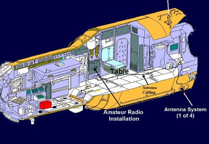
and school students using handheld systems that
can be moved throughout the ISS. It will also
support communications experimentation that
will enable students and radio amateurs to
receive telemetry data from ISS.
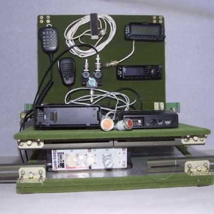
Phase 1 Hardware Overview
The ARISS team has developed all the hardware
elements for the Phase 1 radio system. These
hardware elements have been flown to ISS on
ARISS Hardware in Service Module three Shuttle flights. The Phase 1 system
Figure 2 supports voice and packet (computer-to-
computer radio link) capabilities. Packet radio
provided this foundation through the installation has several capabilities including an APRS
of four ham radio antenna feedthrough ports on Instant Messaging-type system and a Bulletin
the Russian Service Module. With these Board System that allows radio amateurs to store
antennas in place, the primary location of the and forward messages and allows the orbiting
ham station will reside inside the Russian crew to send e-mail to all hams or to individuals.
Service Module (SM) named Zvezda. The ham
station will be installed near the SM dining table. The Phase 1 ham radio system was developed
See figure 2. Simultaneous multi-band primarily in the US. However, extensive testing
operations can be conducted with these two (SM and coordination with the ARISS-Russia team
and FGB) station locations. was required since it is installed in the ISS
Russian segment. The initial portion of the
The ARISS team is also working with the Phase 1 ISS Ham radio system was launched on-
international space agencies to install externally- board the STS-106 Space Shuttle Atlantis
mounted amateur radio equipment on the ISS. mission on September 8, 2000. This system
This hardware will enable the crew to consists of two hand-held Ericsson MP-A
communicate with Earth-bound radio amateurs transceivers for 2 meters and 70 cm, a power
adapter, an adapter module, an antenna
system, a packet module, a headset
assembly, and the required cable
assemblies (see figures 3, 4 and 5).
This configuration can be operated in the
attended mode for voice communications
and either the
attended or
automatic mode for
packet
communications.
Additional ARISS
Phase 1 hardware
was deployed
during two
ISS Ham Phase 1 System in the FGB
additional Shuttle Ericsson Radio
Figure 3
flights to ISS. This Figure 4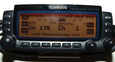
hardware included an                                       VHF/UHF flexible
                       additional        Packet                                   tape      antennas.
                       Module on the STS-105                                      WA4 includes a
                       Discovery flight on                                        2.5 meter flexible
                       August 10, 2001 (see                                       tape HF antenna.
                       Figure 6), and additional                                  The         antenna
                       cables and modules to                                      systems        were
                       support simultaneous 2                                     developed by the
 Phase 1 Hardware      meter and 70 cm                Phase 1 Packet Module       U.S., Italian, and
      Figure 5         operation on the STS-                 Figure 6             Russian      ARISS
                       108 Endeavour flight on                                    partners.
                       December 5, 2001.
Details of the Phase 1 system are described in       Each antenna assembly consists of a mounting
reference 1.                                         plate, spacer, a black striped handle, a Russian
                                                     handrail clamp, an orange-colored VHF/UHF (or
Antenna Assemblies                                   HF) metal flexible tape antenna with black delrin
                                                     mounting collar, an L/S band flat spiral antenna
In 2002, a set of four antenna systems,              with a white delrin radome cover, a diplexer
developed by the ARISS team, were deployed           (mounted      underneath     the   plate)    and
during three Russian EVAs. These antennas will       interconnecting RF cables. See figure 8.
support the Phase 1 and Phase 2 systems in the
Service Module.       Once checked out, the          The
specially designed antenna assemblies will           antenna
permit operations on HF (20 meters, 15 meters        systems
& 10 meters), VHF (2-meters), UHF (70cm),            were
and the microwave bands (L and S band) These         launched
antennas also permit the reception of the Russian    on      the
Glisser EVA video signals (2.0 GHz). This            Space
dual-use (Ham/EVA video) capability is the           Shuttle
primary reason the ARISS team received access        Endeavour       Antenna Systems WA1-WA4
                                to    the     four   flight   on               Figure 8
                                          antenna    December 5, 2001. The two up-looking (zenith)
                                    feedthroughs     antennas, WA3 and WA4, were deployed by
                                located on the       EVA (space walk) in January 2002 and the two
                                outside of the       down-looking (Nadir) antennas, WA1 and WA2,
                                Service Module.      were deployed by EVA in August 2002.

                               A total of four       Antenna    installation  EVA      procedure
                               antenna systems       development and training was led by Sergej
                               were developed        Samburov from Energia with support from the
                               to get maximum        ARISS-USA team.
                               use     of     the
                                         antenna           PHASE-2 HARDWARE SYSTEM
  Antenna Location from            feedthroughs.
  End of Service Module        These        were     Phase 2 Hardware Overview
          Figure 7             installed  around
                               the periphery of      The Phase 2 hardware system is expected to
the far end of the Service Module. See figure 7.     exploit the new antenna systems installed on the
Three of the antennas (WA1-WA3) include a            Service Module. Two new radio systems will be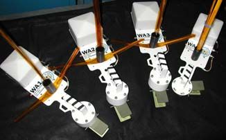
installed as part of Phase 2. These systems will
augment the two Ericsson radio systems already
on-board the ISS as part of the Phase 1 system.
Combined, the Phase 1 and Phase 2 system will
provide more capabilities for the crew and
permit simultaneous, multi-mode operations by
more than one crew member.

The Phase 2 development is a joint Russian, U.S.
and Japan activity. Development was led by
Russian team member Sergej Samburov,
RV3DR. The Russian team was responsible for
certifying the hardware for flight and providing
the ride on the Progress launch vehicle. The
Japanese team provided (donated) the Kenwood
radios to the ARISS team and made specific
hardware and firmware modifications to the
                                                                   Phase 2 Hardware Housed in
radio system to prepare it for flight. The USA
                                                                          Velcro Table
team, in conjunction with the Japan and Russian
                                                                            Figure 9
team, developed the Program Memory software
that provides a powerful system with a very
user-friendly interface for crew.                   assembly developed by the USA team, a
                                                    computer and the 70 cm Phase 1 hardware
One of the two radios qualified for flight is a     system. These will be mounted on a Velcro-
Kenwood TM-D700 radio. This radio supports          backed table. See figure 9. These radio systems
2 meter (144-146 MHz) and 70 cm (435-438            will be connected to the four Service Module
MHz) transmit/receive operation and L-band          antenna systems through a Russian developed
uplink operation. This radio provides a higher      antenna switching system. See figure 10. A
output power capability (10-25 Watts) than the      schematic of the hardware configuration is
Phase 1 radio system and can support FM and         shown in figure 11.
packet operations. The higher power capability                 WA1             WA2             WA3              WA4
should allow nearly horizon-to-horizon signal
reception using simple hand-held radios or          RF Switching
                                                     Assembly
scanners.

The other radio is a Yaesu FT-100. This radio
system will permit operation in the high                                                                  Antenna
                                                                                                           Tuner
frequency bands.      Of particular interest is                      Glisser         Glisser          Glisser         Glisser
performing        ionospheric       propagation
                                                                         Phase 1           2m/70 cm         HF
experimentation using the WA4 (high                      Kenwood
                                                                        (Ericsson)
                                                                                                      Yaesu
                                                          D-700E                                      FT-100
frequency) antenna and this radio. This radio                             70 cm

also supports higher output power capabilities on
2 meters and 70 cm.                                        RF Layout of ISS Ham Radio Systems
                                                                         Figure 10
The entire set of Phase 2 hardware consists of
the Kenwood and Yaesu radios, an RF tuning          Kenwood D-700 Specifics
unit for the Yaesu radio system, interconnecting
signal and RF cables, two specially developed       The ARISS and Kenwood teams agreed that the
Energia power supplies, a power distribution        Kenwood European model radio, D-700E, would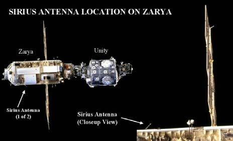
7) Incorporating a channel designator for
    Phase 1
                                                            the front panel as the default instead of
                      Yaesu           Kenwood
    Ericsson                                                the frequency information.
                      FT-100          D-700E
    70 cm
                                                      The architecture of the radio interface to the
                                                      crew was carefully crafted by the USA and
                      Power            Power          Japan team to make the D-700 a powerful radio
                     Supply 2         Supply 1        system with a simple user interface. A set of 5
                                                      default options, or Programmable Memories,
                                                      were embedded in the D700 to support ISS
                                                      operations. See figure 12. The advantage of
                                                      these five Program Memories (PM’s) are that
      Spares 70 cm      FT-100   D-700                they can be restored with a two-button key press
                                                      by the crew at any time. With the two hundred
   Power Distribution Assembly                        different frequency channels, the nearly one
                                                      hundred TNC parameters, and the variety of
                    Power                             applications for this radio on orbit, the default
                    Receptacle                        configurations are absolutely critical to being
                                                      able to maintain communications with the crew
         Power Distribution Schematic                 under all conditions. These five configurations
                  Figure 11                           reduce operations to these fundamental
                                                      configuration baselines:
be used for flight and ground operations. This
radio was already certified by the Russian team.

Several modifications were made by the
Kenwood Japan and Kenwood Moscow
(Bermos) teams to prepare this radio system for
flight. These included:
    1) Developing a special Memory Control
        Program        (MCP)       to       support
        reprogramming of the radio in the USA,
        Japan      and    Russia      to    ARISS                      Kenwood D-700
        specifications                                                PM1 Crew Display
    2) Changing the packet radio default                                  Figure 12
        parameters, as specified by the ARISS
        team, in EEPROM memory
    3) Enhancing the “repeater mode” of the           PM1: Voice Operations (mono band)
        radio system                                  PM2: Voice Operations (cross band/repeater)
    4) Replacing the power cable and the              PM3: APRS/Packet and BBS operations
        microphone and control head cables with       PM4: Attached PC and packet operations
        flight cables to allow certification of the   PM5: Emergency Voice and alternate 9600
        hardware to the Russian requirements.         baud Packet Operations.
    5) Reducing the maximum power output of           PM-off:       No defaults. This mode is for
        the radio to 25 watts                         knowledgeable licensed crew member’s
    6) Replacement of the 6-pin data connector        experimentation
        with an 8-pin connector. One of the
        additional pins on this connector supports    The PM’s remember the following types of
        an 8 V DC output capability.                  parameters for the radio: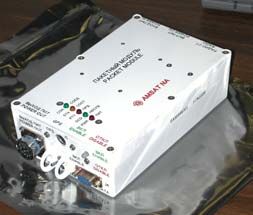
•   Default Channel for LEFT side and RIGHT            Yaesu FT-100 Specifics
    side of radio
•   Which side of radio the Microphone and             The ARISS technical team working on the
    PTT will activate                                  Yaesu      project    has    specified     several
•   Which side of the radio the TNC will               modifications to the Yaesu radio system to
    RECEIVE and on which side it will                  prepare it for flight.      These modifications
    Transmit                                           include:
•   The function of the several “soft keys” on             1. Replacing the power cable and the
    the radio front panel                                     microphone and control head cables with
                                                              flight cables to allow certification of the
While the MCP program stores all 200                          hardware to the Russian requirements.
frequency channels in the radio, the PM’s do not           2. Reducing the maximum power output of
store any combination of channel frequencies                  the radio to 25 watts
other than the initial two defaults for the left and       3. Replacing the PVC RF cables and
right side of the radio. This means, that once a              connectors on the back of the radio with
PM has been selected by the crew, this only                   SMA connectors. Attached to these are
configures the radio to a known default pair of               Teflon coated RG-142 antenna cables
channels. The crew member can still tune to                   with N connectors
any channel after that. Thus, with a push of two           4. Tuner cable replacement with flight
buttons and a rotation of the main dial, the crew             cables
member can operate on multiple modes and                   5. Replacement of 6-pin data connector
different frequency pairs.            While this              with an 8-pin connector. One of the
architecture offers the ultimate in flexibility               additional pins on this connector supports
(millions of combinations), it also provides a                a 12 V DC output capability.
user-friendly interface of the five PM’s to
always return the radio to a known initial state.      Since the FT-100 supports HF operation and the
                                                       WA4 antenna is a single 2.5 meter vertical the
Each of the 200 memory channels can support            ARISS team felt that it would be best to supply a
separate TX and RX frequencies, offsets, and           tuner with the radio to minimize SWR concerns
PL or CTCSS tones. The D700 is a dual radio            and optimize signal output. See figure 11. The
system and although it only supports two               ARISS USA team is working closely with the
channels at a time, it is very important to            Yeasu team to modify their existing FT-100
remember that each channel consists of both a          auto-tuner for ham radio operations on ISS.
displayed RECEIVE frequency and a separate
TRANSMIT frequency. Thus, at any time,                 Development of the Yaesu system is on-going,
there can be up to four frequencies involved in        but is expected to conclude in early November
radio operations. Since the Microphone and             2003.
PTT (for voice) can be using one channel and
the TNC can be using the same or the other             Power Distribution Assembly
channel, or even can transmit on one channel
and receive on the other, there are many               One of the primary issues in a household is
conventional (e.g. simplex, split) and non-            sufficient and easy access to electrical
conventional (e.g. crossband, repeater, CTCSS-         receptacles. A similar issue exists on ISS.
enabled command uplink digital channels, etc)          There just aren’t enough receptacles where you
ways to use these combinations for ARISS.              need them. With the 3 radio systems being
                                                       installed in the Service Module (Phase 1 70 cm,
                                                       Phase 2 Kenwood and Phase 2 Yaesu), the need
                                                       for electrical receptacles for the ISS ham radio
                                                       system could become a major issue.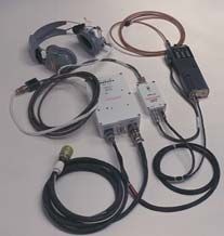
The power distribution assembly, see figures 11       These power
and 13, resolves this problem and several other       supplies
potential issues on ISS. The power distribution       convert the 28
assembly allows the ISS ham system in the             VDC           ISS
Service Module to be plugged into only one ISS        power to 13
receptacle. It also provides a power shutoff          VDC for use
capability via switches and circuit breaker           by             the
protection for each radio system. This not only       Kenwood and               Power Converter
provides an addition level of safety but also         Yaesu       radio            Figure 14
provides an additional shut-down feature that is      systems. Since
critical for satisfying the ISS EVA safety            the power converters are fully redundant, the ISS
requirements.     With the power distribution         ham team will have adequate power capabilities
assembly, there will be no need to plug and           for all the radio systems even if one of the power
unplug ISS Ham items due to insufficient              converters fail.
receptacles. Thus, this assembly serves to
reduce wear and tear on the power cables,             Phase 2 Delivery, Testing and Checkout
improving system safety.
                                                      The final version of the flight MCP software was
                                                      delivered to the Russian team by the USA team
                                                      on July 17, 2003. Just prior to this, the
                                                      Kenwood Japan team delivered the final
                                                      firmware load to the Kenwood Japan (Bermos)
                                                      team for installation into the D-700 radio. The
                                                      Bermos team and the ARISS-Russia team, led
                                                      by Sergej Samburov, completed the hardware
          Power Distribution Assembly                 and software modifications to the radio system
                   Figure 13                          in late July and readied the Phase 2 hardware
                                                      system for flight. The initial set of Phase 2
                                                      hardware, including the Kenwood D-700 radio,
The Power Distribution Assembly is being              interconnecting cables, power converters, and
developed by the USA team with strong support         RF switching system were delivered to the
from the Russian team. While the unit will be         Baikonur Cosmodrome in Kazakhstan in early
fabricated in the US, several of the parts,           August. The Phase 2 hardware was launched on
particularly the electrical connectors, are           the Progress 12P rocket on August 29, 2003 and
Russian supplied. The current plan for the            docked with the ISS on August 31. The Velcro
Power Distribution Assembly is to fabricate the       table is already on-board ISS and is awaiting
flight unit, certify it for flight in the US and in   equipment installation.
Russia and then fly it on-board the next space
shuttle. Since the Yaesu system will not be           The Phase 2 equipment is currently “yellow
deployed until the Spring of 2004, this               tagged” meaning that we need to accomplish
development and delivery schedule appears to          some additional tests prior to on-board hardware
make sense.                                           integration and testing. A series of tests are
                                                      being planned for early November, 2003 at the
Power Converters                                      KIS facility (Service Module engineering model
                                                      equivalent) located at Energia in Korelev
Two fully redundant, flight certified power           (Moscow area) Russia. The Russian and US
converters were developed by the Russian              team will be conducting tests in this Service
Energia team and were supplied to the ISS Ham         Module equivalent to validate that the Phase 2
team for use as part of the Phase 2 radio system.     and 70 cm and 2 meter Phase 1 systems are
compatible with the other electrical systems on CONCLUSIONS
the Service Module. We will also conduct some
RF testing with the flight-identical antenna The ARISS-international team, with help from
systems and the Phase 1 and Phase 2 hardware. Kenwood and Yaesu, have developed the ISS
Once these tests are successfully completed, the Phase 2 ham radio system. The Kenwood
yellow tag can be removed and hardware system is currently on-orbit and will be soon
installation can begin. operational on ISS. The team expects that the
Yaesu system will be operational in Spring
The current plan is for Mike Foale and 2004. This multi-national development effort
Alexander Kaleri to install the Phase 2 and presented many challenges to the team. Despite
Phase 1 70 cm hardware on Expedition 8. The these challenges, the tremendous teamwork and
plan is to perform hardware installation and optimistic spirit resulted in an outstanding new
checkout in mid to late November 2003. capability on ISS that we expect to set the
standard in space for years to come.
The remaining Phase 2 hardware, including the
Yeasu radio system is planned to be launched on ACKNOWLEDGEMENTS
the Progress 14P flight that is planned for
January 2004. The authors would like to acknowledge the
tremendous support, teamwork and volunteer
spirit of the ARISS-International team in making
FUTURE HARDWARE DEPLOYMENTS this hardware system come to fruition.
Technical, financial and administrative support
Follow-on Phase 2 Hardware by the ARISS member organizations--the
AMSAT organizations and IARU organizations
Two future projects are envisioned to improve (ARRL in the USA) continue to be crucial to the
the capabilities of the Phase 2 system. These success of the program. Also special recognition
include the development of the tuner for the is in order to NASA, Energia, Kenwood, and
Yaesu radio system and the certification of a Yaesu. The ARISS team continues to be
Standing Wave Ratio/Power meter. These two indebted to them for all their in-kind
projects will be developed and flight certified by contributions and support. Together we are
the US team and flown on a future shuttle flight. pioneering the new frontiers of amateur radio
and educational outreach.
SSTV
DEDICATION
In the near future, a Slow Scan Television
(SSTV) system will be deployed on ISS. The This paper is dedicated to the memory of Roy
SSTV system for the ISS ham radio station is Neal, K6DUE. Roy’s tireless pursuit to make
currently in development. This system will amateur radio on human spaceflight missions a
consist of a software interface, developed by the permanent capability was an inspiration to us all.
MAREX-MG team and a hardware interface, We feel privileged to have realized his vision on
developed by the AMSAT-NA hardware team. ISS during his lifetime. We have more solidly
Prototype hardware and software systems have cemented that permanence with the delivery of
been developed and the flight system fabrication the Phase 2 hardware system. Our thoughts and
has started. The SSTV system will allow digital prayers are with you old buddy.
still pictures to be uplinked and downlinked in
both crew-tended and autonomous modes. The
ARISS team expects the SSTV system to be
flown on Progress flight 14P in January 2004.REFERENCES
1. Bauer, F., McFadin, L., Steiner, M., and
Conley, C., “Amateur Radio on the
International Space Station---the First
Operational Payload on the ISS.”
Proceedings from the World Space
Congress, 2002
2. Watarikawa, H., and Aota, S., ARISS D-
700 Users Manual, July 15, 2003
3. Bauer, F. and McFadin, L., “SAREX
Hardware Configurations and Flight
Operations Support” Proceedings of the
AMSAT-NA Tenth Space Symposium,
October, 1992.
4. Bauer, F. and Marchant, W., “Amateur
Radio on the International Space
Station,” Proceedings of the AMSAT-
NA Sixteenth Space Symposium,
October 1998.
5. "Joint NASA-Energia Meeting on
Amateur Radio for the International
Space Station Held at Johnson Space
Center, Houston, Texas 22-27 January
1999," The AMSAT Journal,
July/August 1999.
For more information on the ARISS program,
you are welcome to visit the ARISS web page at:
http://ariss.gsfc.nasa.gov or
http://www.rac.ca/arissYou can also read