Multi-Radio Integrated Navigation System M&S Software Design for GNSS Backup under Navigation Warfare - MDPI
←
→
Page content transcription
If your browser does not render page correctly, please read the page content below
Article
Multi-Radio Integrated Navigation System M&S
Software Design for GNSS Backup under Navigation
Warfare
Heyone Kim 1, Junhak Lee 2, Sang Heon Oh 3, Hyoungmin So 4 and Dong-Hwan Hwang 1,*
 1 Department of Electronics Engineering, Chungnam National University, Daejeon 34134, Korea;
   heyone8@cnu.ac.kr
 2 Research & Development Division, Korea Aerospace Industries Ltd., Gyeongnam 52529, Korea;

   junhak.lee@koreaaero.com
 3 Integrated Navigation Division, Navcours Co., Ltd., Daejeon 34014, Korea; laborosh@navcours.com

 4 Agency for Defense Development, Daejeon 34186, Korea; hmso@add.re.kr

 * Correspondence: dhhwang@cnu.ac.kr; Tel.: +82-42-821-5670

 Received: 22 December 2018; Accepted: 31 January 2019; Published: 6 February 2019

 Abstract: To avoid degradation of navigation performance in the navigation warfare environment,
 the multi-radio integrated navigation system can be used, in which all available radio navigation
 systems are integrated to back up Global Navigation Satellite System (GNSS) when the GNSS is not
 available. Before real-time multi-radio integrated navigation systems are deployed, time and cost
 can be saved when the modeling and simulation (M&S) software is used in the performance
 evaluation. When the multi-radio integrated navigation system M&S is comprised of independent
 function modules, it is easy to modify and/or to replace the function modules. In this paper, the
 M&S software design method was proposed for multi-radio integrated navigation systems as a
 GNSS backup under the navigation warfare. The M&S software in the proposed design method
 consists of a message broker and function modules. All the messages were transferred through the
 message broker in order to be exchanged between the function modules. The function modules in
 the M&S software were independently operated due to the message broker. A message broker-
 based M&S software was designed for a multi-radio integrated navigation system. In order to show
 the feasibility of the proposed design method, the M&S software was implemented for Global
 Positioning System (GPS), Korean Navigation Satellite System (KNSS), enhanced Long range
 navigation (eLoran), Loran-C, and Distance Measuring Equipment/Very high-frequency
 Omnidirectional Radio range (DME/VOR). The usefulness of the proposed design method was
 shown by checking the accuracy and availability of the GPS only navigation and the multi-radio
 integrated navigation system under the attack of jamming to GPS.

 Keywords: GNSS backup; alternative navigation; multi-radio integrated navigation system; M&S
 software; message broker; navigation warfare; jamming

1. Introduction
     The simulation is defined as the imitative representation of the functioning of one system or
process by means of the function of another and the modeling is defined as producing a
representation or simulation [1]. Navigation warfare is defined as protecting the use of PNT (position,
navigation and timing) information by friendly forces against the hostile attack with the electronic
warfare method [2]. Since the received Global Navigation Satellite System (GNSS) signal strength is
very weak and the signal structure of GNSS for civil use is open to the public, GNSS can be easily
attacked by jamming, meaconing, and spoofing under the navigation warfare [3,4]. In order to
overcome this weak point of the GNSS, other radio navigation systems can be integrated with the
Electronics 2019, 8, 188; doi:10.3390/electronics8020188                    www.mdpi.com/journal/electronics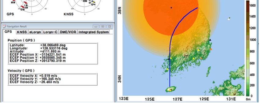
Electronics 2019, 8, 188                                                                       2 of 16

GNSS [3,5,6]. The FAA (Federal Aviation Administration) in the U.S. has announced a plan to use
ground-based radio navigation systems when the GPS (Global Positioning System) is attacked by
jamming and/or spoofing [6,7]. An alternative navigation system with enhanced Long-range
navigation (eLoran) and the GNSS for marine navigation was proposed by the GLA (General
Lighthouse Authority) in the U.K. [8]. Research on the multi-radio integrated navigation system has
been conducted in Korea [9–13]. A regional satellite navigation system and ground-based radio
navigation systems are additionally used with GPS in order to have a continuous navigation solution
[9,10,14]. The regional satellite navigation system with seven satellites, called the KNSS (Korean
Navigation Satellite System), will be deployed by the Korean government. Ground-based radio
navigation systems include DME (Distance Measuring Equipment), Loran-C (Long-range
navigation), e-Loran, and VOR (Very high-frequency Omnidirectional Radio range). Even though the
KNSS and ground-based radio navigation systems are used with GPS, navigation performance can
be unsatisfactory. In this case, fixed and/or moving pseudo-satellites (pseudolites) will be
additionally integrated.
      Before real-time radio navigation systems are deployed, lots of tests and performance
evaluations should be carried out. The M&S (modeling and simulation) software can be used for
performance evaluation in order to save cost and time [9,15]. When the software is not complicated,
it may be efficient to design the software in one module. However, when the software is sophisticated,
it is more efficient to design a modularized software. By modularizing, it is easy to modify and/or to
replace the software [16–20].
      In this paper, a message broker-based M&S software design method was proposed. The whole
M&S software was divided into function modules in the proposed design method. All the messages
were transferred through the message broker in order to be exchanged between the function modules.
Due to the message broker, each function module could be independently operated. A message
broker-based multi-radio integrated navigation M&S software was designed using the proposed
method. The M&S software was comprised of a GUI module, a navigation environment generation
module, a navigation algorithm module, a coverage analysis module, and an M&S message broker.
In order to show the feasibility of the proposed design method, the M&S software was implemented
for GPS, KNSS, eLoran, Loran-C, and DME/VOR. The M&S software was programmed in Visual C++
under a Windows 10 operating system. The performance of the multi-radio integrated navigation
system was evaluated under the navigation warfare environment through the M&S software. The
results of the multi-radio integrated navigation system were compared with those of GPS only
navigation when the GPS was attacked by a jammer. This is an extension of the authors’ conference
paper [21]. The effect of the jammer power to GPS measurements was modeled and included in the
navigation environment generation module of the implemented M&S software. The navigation
warfare scenario editor was added in the graphical user interface (GUI) for the M&S parameter
setting.
      In section 2, the scheme of the M&S software is described for the performance evaluation of the
multi-radio integrated navigation system. A message broker-based software design method is
proposed. A message broker-based multi-radio integrated navigation M&S software was designed
using the proposed method. In section 3, the M&S software is implemented. In section 4, the
performance of the navigation systems in the M&S software is evaluated. Finally concluding remarks
and further studies are presented in section 5.

2. M&S Software Design for Multi-Radio Integrated Navigation System

2.1. Multi-Radio Integrated Navigation System M&S Software
     Multi-radio integrated navigation systems consist of signal sources, receivers, and integrated
navigation algorithm [3,5]. The signal sources include navigation satellites and ground-based radio
navigation stations. The receivers process the signals from the signal source to generate
measurements and navigation outputs. The integrated navigation algorithm gives the output of the
system from measurements and navigation outputs.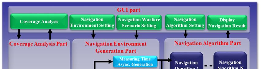
Electronics 2019, 8, 188                                                                        3 of 16

     Measurements are generated by the receivers from received signals. The signals in some
frequency bands can be blocked by obstacles in the signal path. Errors in the measurements are
caused by the signal source, signal distortion in the channel, and the receiver [3,5]. The position,
velocity, and clock of the signal source contain uncertainties and the signal distortion depends on the
channel characteristics. Receiver errors are caused by the antenna and the RF (radio frequency) front-
end [3,5]. When the receiver is under attack of a jammer, no measurements or measurements with a
large error are available [4].
     For a given navigation performance and distribution of the signal sources, coverage analysis can
be performed to check the area at which the performance is satisfied. Signal sources can be
additionally placed to have better coverage analysis results. Optimal placement of the additional
navigation signal sources can be determined to maximize the results [22,23]. This optimal placement
of the signal sources is called gap filling [14,23].
     The multi-radio integrated navigation system M&S software should provide various navigation
environments and operation scenarios. Measurements for various navigation environments and
operation scenarios should be generated to test a multi-radio integrated navigation algorithm. The
display for navigation results and internal variables of the M&S software should be provided to
developers and operators. If the tested navigation results are not satisfied, new signal sources can be
placed through the coverage analysis. Figure 1 is the schematic diagram of the multi-radio integrated
navigation M&S software.

      Figure 1. Schematic diagram of the multi-radio integrated navigation system modeling and
      simulation (M&S) software.

2.2. Message Broker-Based Software Design Method
     As shown in Figure 2, the message broker-based software consisted of the message broker and
the function modules. All the messages were transferred through the message broker in order to be
exchanged between the function modules. A complex function with a large size could be easily
divided into several modules and the function modules could be connected through the message
broker. The message broker had all I/Fs (interfaces) of the function modules. The function module
had only one I/F to exchange data with the other function modules. Due to the message broker, each
function module did not need to contain all the I/Fs.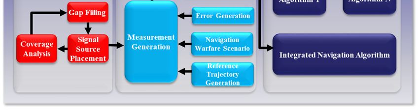
Electronics 2019, 8, 188                                                                         4 of 16

                              Figure 2. Diagram of message broker-based software.

2.2.1. Message Broker
    As shown in Figure 3, the message broker consisted of a destination finder, a destination selector,
and the I/Fs. The message broker received a message from a function module and interpreted the
message. Then the message broker transmitted the message to the destination function module
through a corresponding I/F. The source ID, the destination ID, and the data were contained in the
message, as shown in Table 1.

                                              Table 1. Message structure.

                  Field No.    Field Name                           Description
                      1       Message header                 Beginning of the message
                      2         Source ID               Transmitting function module ID
                      3       Destination ID              Receiving function module ID
                      4        Message ID                        Type of the data
                      5           Status             Operational status of transmitting module
                      6        Data length                   Number of bytes of data
                      7            Data                             Binary data

                                                    Message Broker
                                                                       Dest. ID
                                  Destination Finder

                                        Message                              Destination
                                                                              Selector
                                                                                   Destination
                                                       Message

                                                              I/F
                                    I/F 1           I/F 2           ......         I/F N

                                    I/F 1           I/F 2                          I/F N
                                   Function        Function         ......        Function
                                   Module          Module                         Module
                                      1               2                              N

                                   Figure 3. Diagram of the message broker.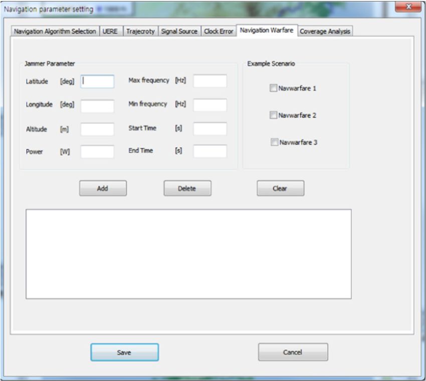
Electronics 2019, 8, 188                                                                              5 of 16

2.2.2. Function Module
    As shown in Figure 4, the function module consisted of an I/F, an encoder, a decoder, and a
procedure. The binary data in the received messages were converted into internal variables of the
procedure by the decoder. The internal variables were converted into the binary data by the encoder.
The procedure was the program code of the function module of the M&S software. Due to the encoder
and decoder, each function module did not need to share variables of the procedure with the other
function modules. If the operators and/or developers updated the encoder and decoder, developed
programs in other platforms could be reused or easily ported in the function module [18,20,24,25].

                                 Figure 4. Diagram of the function module.

2.3. Design of a Message Broker-Based M&S Software for the Multi-Radio Integrated Navigation System
     Figure 5 shows the message broker-based M&S software for the multi-radio integrated
navigation system. The software consisted of a navigation environment generation module, a
navigation algorithm module, a coverage analysis module, and a GUI module. A function module of
the message broker-based M&S software design method corresponded to each part of the multi-radio
integrated navigation system M&S software (Figure 1).

          Figure 5. M&S message broker-based software for multi-radio integrated navigation system.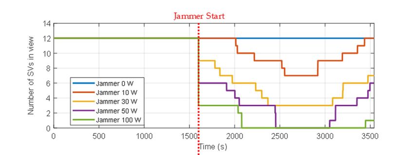
Electronics 2019, 8, 188                                                                                               6 of 16

     Figure 6 represents the operation of the M&S software for the multi-radio integrated navigation
system in the state diagram. The state transition of the state diagram is given in Table 2. Table 3 shows
conditions for state transition and flags of state transition. When the M&S program started, the
program was in the initialization mode. If the function module parameters were available, the
program went to standby mode. Then it went to the coverage analysis mode, the measurement
generation and the navigation mode, or the navigation only mode, according to the condition.

                                       Start
                                                          Initialization

                                               6      1                2       5

                            Coverage                                                       Navigation
                                                            Stand-by
                            analysis                                                         only
                                               3                                   6
                                                      4                6

                                                                                                       Exit
                                                          Measurement
                                                                                          Exit
                                                          generation and
                                                            navigation

                                                                                   Exit

             Figure 6. State diagram of the M&S software for multi-radio integrated navigation system.

                                                   Table 2. State transition.

                                                                                        Measurement
             Next                                                  Coverage                                   Navigation
                            Initialization     Stand-by                                generation and
 Current                                                           analysis                                     only
                                                                                         navigation
  Initialization                 —                  1                 N/A1                  N/A                  N/A
    Stand-by                     2                  —                  3                     4                    5
    Coverage
                                N/A                  6                 —                         N/A             N/A
    analysis
  Measurement
 generation and                 N/A                  6                N/A                        —               N/A
   navigation
 Navigation only                N/A                  6                N/A                        N/A              —
                                                             1   Not allowed

                                          Table 3. Condition for state transition.

   Condition
                                                                     Description
     No.
      1                                     Function module parameters are available
      2                                     ‘Initialization Mode’ command is received
      3                                  ‘Coverage analysis Mode’ command is received
                            Function module parameters are available and ‘Measurement generation and
         4
                                              navigation Mode’ command is received
                           Function module parameters and measurements are available and ‘Navigation
         5
                                                  only Mode’ command is received
         6                            Operation is completed, or ‘Stop’ command is received

2.3.1. Navigation Environment Generation Module
    In the navigation environment generation module, the reference trajectory and errors were
generated, and signal source visibility was determined. The reference trajectory represented the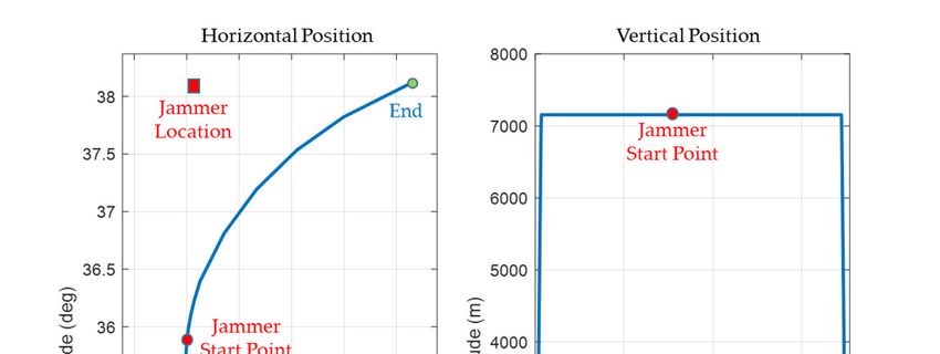
Electronics 2019, 8, 188 7 of 16
motion of the vehicle. The position of the vehicle and the navigation signal source determined the
visibility of the signal sources. If the signal sources were visible to the vehicle, true measurements
were generated and measurement errors were added. If the jammer attacked, the measurements
included the effect as an error. Figure 7 shows the navigation environment generation module block
diagram.
Figure 7. Navigation environment generation.
In Figure 7, the measurement error jam
of GNSS caused by a setting of parameters jamming
attack is modeled as Equation (1).
c 0.2 2 Rc
1 , 1
1.023 2(C / N0 ) T(C / N0 ) B fe
2
c 0.2 1 B feTc 1 2 Rc R
jam 1 1 , 1 c (1)
1.023 2(C / N0 ) B feTc 1 BfeTc T(C / N0 ) B fe B fe
c 0.2 1 1 Rc
1 , 1
1.023 2(C / N0 ) B feTc T(C / N0 ) Bfe
where B fe and T c denote the double-sided front-end bandwidth and the code chip rate of GPS
receiver, respectively. c denotes the speed of light and T is the integration time. Carrier power
to noise density ratio C / N 0 is given in Equation (2).
C / N0 eff ,dB 1
J / SdB 4.5
C / N0 10log10 10 10
10 10 (2)
2.22Rc
where C / N 0 eff , dB
is the effective carrier-to-noise power ratio. The jamming-to-signal power ratio
J / S is given in Equation (3).
dB
4
J / S dB
10 log 10 Jt ,W Gt dB G j
dB
20 log 10
j
r Sr dB
(3)
dB
where Jt ,W , G t , and G j
denote jammer transmitted power, jammer transmitter antenna gain, and
receiver antenna gain toward the jammer, respectively. j , r , and S are the wavelength of the
r dB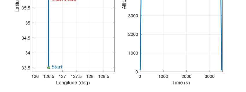
Electronics 2019, 8, 188                                                                           8 of 16

jamming, the distance from the receiver to the jammer, and the signal power at the receiver antenna
input, respectively.

2.3.2. Coverage Analysis Module
     Figure 8 shows the coverage analysis module block diagram. The gap was calculated from the
signal source specification, target region, signal source location, and measurement error
characteristics in the coverage analysis module. The location for the additional signal source was
determined from signal source specification, target region, signal source location, measurement error
characteristics, gap, and conditions for gap filling algorithm.

                                       Figure 8. Coverage analysis.

2.3.3. Navigation Algorithm Module
     Figure 9 shows the navigation algorithm module block diagram. An integrated navigation
algorithm was constructed from radio navigation algorithms. The navigation results could be
obtained from the least squares method, the weighted least squares method, and the Kalman filtering
method.

                                     Figure 9. Navigation algorithm.

2.3.4. GUI Module
      The GUI module had displays for the parameter setting. The motion of the vehicle, the signal
source information, navigation algorithms, navigation warfare information, and error characteristics
could be changed through the setting of parameters. The GUI module displayed the reference
trajectory, signal source locations, measurements, navigation results, and coverage analysis results [10].

3. Implementation of the M&S Software
Electronics 2019, 8, 188 9 of 16
The feasibility of the proposed design method is shown through implementation of the message
broker-based multi-radio integrated navigation system M&S software for GPS, KNSS, eLoran, Loran-
C and DME/VOR [9,10], [26–28]. MFC library and sockets were used in the implementation [29,30].
The M&S message broker and function modules were implemented in the tasks. All the tasks
included threads and queues, as shown in Table 4. The M&S message broker could be represented in
the task, as shown in Figure 10. The function modules could be similarly represented.
M&S Message Broker
Destination
Queue
Destination
Finder Selector
Queue
Queue
I/F 1 I/F 4
I/F 2
I/F 3
Input Input
M&S M&S
Message Message
Output Output
M&S Input M&S
Message M&S Message
Message Output Input
Output M&S
M&S M&S
Message Message
Message
Figure 10. M&S message broker task.
Table 4. Task, thread, and queue in the implementation.
Thread
Task Name Queue
Number Name
M&S message broker 6 Destination finder, destination selector, 4 I/Fs 9
Navigation environment Encoder, decoder, I/F, reference trajectory generation, 6
10 16
generation raw measurement generations
Encoder, decoder, I/F,
Coverage analysis 5 6
coverage analysis, gap filling
Encoder, decoder, I/F, 6 navigation algorithms,
Navigation algorithm 10 14
integrated navigation algorithm
Encoder, decoder, I/F, 20 threads for display and
GUI 23 42
parameter setting
Figure 11 shows the GUI for navigation warfare scenario parameters setting. Initial values and
motion types were set. If the load button was clicked, the receiver independent exchange format
(RINEX) files of the GPS and the files of the location data of the ground-based navigation system
stations were loaded. If the navigation warfare scenario was edited, the location, operating time and
power of jammer could be set as in Figure 11.Electronics 2019, 8, 188 10 of 16
Figure 11. Graphical user interface (GUI) for navigation warfare scenario parameter setting.
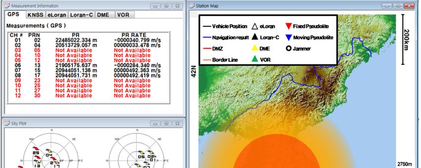
The GUI for measurements, signal sources, navigation results, and navigation warfare situation
is shown in Figure 12. The measurements of the navigation systems are shown in the left upper
window. The sky plots of the GPS and KNSS satellites are shown in the left middle window. The
navigation result of the GPS is shown in the left lower window. The horizontal path of the vehicle,
the locations of the ground-based navigation system stations, and the jamming area are shown in the
right window.
Figure 12. GUI for measurements, signal sources, navigation results and navigation warfare
situation.
4. Performance Evaluation of the Navigation Algorithm through the M&S Software
The performance evaluation was performed for the GPS only navigation system and a multi-
radio integrated navigation system under the navigation warfare environment through the proposedElectronics 2019, 8, 188 11 of 16
M&S software. The measurement errors of the navigation systems in the performance evaluation
were assumed to be white noise Gaussian and their standard deviations are listed in Table 5.
Table 5. Measurement error of navigation system.
Navigation System Measurement Error (1 σ)
GPS 3m
KNSS 10 m
eLoran 10 m
Loran-C 100 m
DME 340 m
VOR 1.5°
The reference trajectory of the vehicle is shown in Figure 13. The jammer was located in the left
of the trajectory, 38.096521 degrees of latitude, 126.576012 degrees of longitude and 300 m of altitude,
as shown in Figure 13. The jammer was set to start its operation at 1600 s and end at 3500 s via the
navigation warfare scenario parameter setting window, shown in Figure 11. It could be seen that the
navigation warfare occurred during the operation of the vehicle. The location and start point of the
jammer are shown in Figure 13. For the multi-radio integrated navigation system, the weighted least
squares method was used. The weights were determined from the measurement error statistics listed
in Table 5. It was assumed that the jammer influenced only the GPS signals. When the J/S (jammer to
signal power ratio) was larger than 40 dB, the measurement was not available, since the signals could
not be tracked in this environment. When the J/S was less than 40 dB, the measurement error caused
by the jammer was added to the measurement.
The performance evaluation was performed for 0, 10, 30, 50, and 100 W of jammer power in the
navigation warfare environment. For 0, 10, 30, 50, and 100 W of jammer power, the number of
satellites in view are shown in the upper graph of Figure 14. The distance from the vehicle to the
jammer is shown in the lower graph of Figure 14. It could be seen that the number of satellites in view
decreased from 1600 s when the jammer started its operation. At the time around 2750 s, when the
distance from the vehicle to the jammer was the shortest, the number of the satellites in view was the
least. It could be observed from these test results that the GPS measurement error due to the jammer
to the navigation warfare scenario was well modeled.
Figure 13. Reference trajectory for performance evaluation.Electronics 2019, 8, 188 12 of 16
Figure 14. Variations of the number of satellites in view and distance between vehicle and jammer.
The position errors of GPS only navigation and the multi-radio integrated navigation system are
shown in Figures 15–18 for the cases of 0 and 50 W of jammer power. In the case of the GPS only
navigation, it was regarded that the normal navigation outputs could be obtained only when PDOP
(position dilution of precision) was less than 10. The position errors are shown in Figure 15 and Figure 16
when there was no jammer. The performance of the multi-radio integrated navigation system in
Figure 16 was similar to that of the GPS only navigation when the GPS was available. This can be
easily expected since the measurements of GPS are more accurate than those of other navigation
systems, as in Table 5. The position errors for the case of 50 W of jammer power are shown in Figure 17
and Figure 18. It can be seen from Figure 17 that the position error increased from the time when the
jammer started, and the navigation outputs were not obtained from the time when the number of
satellites in view was less than four (Figure 14). It can also be seen that the navigation results could
be obtained from the time of 3470 s when the number of satellites in view became more than four. It
can be seen from Figure 18 that the multi-radio integrated navigation system could provide the
continuous navigation output due to the use of the KNSS navigation system and the ground-based
radio navigation systems.
For the variations of jammer power, results of GPS only navigation and the multi-radio
navigation system are listed in Table 6. The availability in Table 6 means the percentage value of the
time interval in which the navigation outputs could be obtained to the whole mission time interval.
It could be observed from the results of the GPS only navigation in Table 6 that the position errors
increased as the jammer power increased from 0 to 50 W and decreased at 100 W. This decrease was
caused by the fact that the navigation error was not included in the calculation when the number of
satellites in view was less than four or the PDOP was greater than 10. It could also be observed in
Table 6 that the availability of the GPS only navigation decreased as the jammer power increased. On
the other hand, it could be seen that the multi-radio integrated navigation provided 100% of the
availability, even though the power of the jammer increased. It can also be observed from the results
of the multi-radio integrated navigation system in Table 6 that the position errors increased as the
jammer power increased. This was due to the fact that the time interval, at which the GPS
measurements were not available, increased as the power of the jammer increased. It could be seen
from the test results that the performance evaluation of the multi-radio integrated navigation
algorithm under the navigation warfare environment could be effectively carried out through the
proposed M&S S/W (software) design method.Electronics 2019, 8, 188 13 of 16
Figure 15. Position error of GPS only navigation with a 0 W jammer.
Figure 16. Position error of multi-radio integrated navigation with a 0 W jammer.Electronics 2019, 8, 188 14 of 16
Jammer Start
Figure 17. Position error of GPS only navigation with a 50 W jammer.
Jammer Start
Figure 18. Position error of multi-radio integrated navigation with a 50 W jammer.
Table 6. Comparison of position error and availability result.
GPS only navigation1 Multi-radio integrated navigation
Jammer Horizontal Vertical Horizontal Vertical
Availability Availability
power Error Error Error Error
(%) (%)
(m, 95%) (m, 95%) (m, 95%) (m, 95%)
0W 2.760 4.183 100.000 2.532 4.007 100.000
10 W 4.382 7.627 99.972 3.639 5.864 100.000
30 W 6.906 10.629 74.506 8.055 8.836 100.000
50 W 7.190 9.664 58.357 9.679 10.124 100.000
100 W 2.810 3.909 45.144 11.404 11.324 100.000
1 Calculated when the PDOP is less than 10Electronics 2019, 8, 188 15 of 16
5. Concluding Remarks and Further Studies
An M&S software design method was proposed for multi-radio integrated navigation systems
as a GNSS backup under navigation warfare. The M&S software in the proposed design method
consisted of a message broker and function modules. A message broker-based M&S software was
designed for a multi-radio integrated navigation system. In order to show the feasibility of the
proposed design method, the M&S software was implemented for GPS, KNSS, eLoran, Loran-C, and
DME/VOR and the performance evaluation was carried out. The results showed that the multi-radio
integrated navigation system provides navigation results continuously, even when the GPS only
navigation system cannot provide navigation results, due to the jamming under a navigation warfare
environment.
In further studies, additional ground stations and fixed/moving pseudolites will be included,
which are newly assigned by the coverage analysis module in the M&S software. Performance
evaluations of the M&S software based on integrity and continuity will be performed.
Author Contributions: Conceptualization, S.H.O, H.S. and D.-H.H.; software, H.K. and J.L.; supervision, D.-H.H.;
validation, H.S.; writing – original draft, H.K., J.L., S.H.O. and D.-H.H.; writing – review & editing, D.-H.H.
Funding: This research was funded by the National GNSS Research Center Program of Defense Acquisition
Program Administration and Agency for Defense Development.
Acknowledgments: This work has been supported by the National GNSS Research Center Program of Defense
Acquisition Program Administration and Agency for Defense Development.
Conflicts of Interest: The authors declare no conflict of interest.
References
1. Merriam Webster. The Merriam-Webster Dictionary, 11th ed.; Merriam Webster Inc.: Springfield, VR, USA,
2008; ISBN 978-0877792956.
2. Department of Defense, Department of Homeland Security, and Department of Transportation. Federal
Radio Navigation Plan 2017; National Technical Information Service: Springfield, VR, USA, 2017; pp. 16–217.
3. Kaplan, E.D.; Hegarty, C.J. Understanding GPS/GNSS: Principles and Applications, 3rd ed.; Artech House:
Boston, FL, USA, 2017; ISBN 978-1-63081-058-0.
4. White, N.A.; Maybeck, P.S.; DeVilbiss, S.L. Detection of interference/jamming and spoofing in a DGPS-
aided inertial system. IEEE Trans. AES 1998, 34, 1208–1217, doi:10.1109/7.722708.
5. Grove, P.D. Principles of GNSS, Inertial, and Multisensor Integrated Navigation Systems, 2nd ed.; Artech House:
Boston, FL, USA, 2013; ISBN 978-1-60807-005-3.
6. Available online: http://www.dtic.mil/dtic/tr/fulltext/u2/a470386.pdf (accessed on 21 December 2018).
7. Eldredge, L.; Enge, P.; Harrison, M.; Kenagy, R.; Lo, S.; Loh, R.; Lilly, R.; Narins, M.; Niles, R. Alternative
positioning, navigation & timing (PNT) study. In Proceedings of the International Civil Aviation
Organization Navigation Systems Panel (NSP) Working Group Meetings, Montreal, QC, Canada, 11–27
May 2010; pp. 1–19.
8. Lo, S.; Enge, P.; Niles, F.; Loh, R.; Eldredge, L.; Narins, M. Preliminary assessment of alternative navigation
means for civil aviation. In Proceedings of the 2010 International Technical Meeting of the Institute of
Navigation, San Diego, CA, USA, 25–27 January 2010; Institute of Navigation: Manassas, VR, USA, 2010;
pp. 314–322.
9. Kee, C.; Lee, Y.J.; Hwang, D.-H. Final Report of National GNSS Research Center Satellite Navigation System
Architecture Laboratory 2nd Phase; Agency for Defense Development: Daejeon, Korea, 2015; pp. 8–439.
10. Kee, C.; Lee, Y.J.; Hwang, D.-H. Intermediate Report of National GNSS Research Center Satellite Navigation
System Architecture Laboratory 3rd Phase; Agency for Defense Development: Daejeon, Korea, 2017; pp. 116–
232.
11. Choi, M.; Won, D.; Jeon, H.; Kim, D.; Sung, S.; Lee, Y.J. Navigation performance analysis according to the
Korean navigation satellite system of bit design elements. In Proceedings of the 2012 KSASS Autumn
Conference, Jeju, Korea, 14–16 November 2012; Korea Society for Aeronautical & Space Sciences: Seoul,
Korea, 2012; pp. 626–630.Electronics 2019, 8, 188 16 of 16
12. Choi, M.; Won, D.; Sung, S.; Lee, J.; Kim, J.; Lee, Y.J. Korean navigation satellite system orbit design and
navigation performance analysis. In Proceedings of the 2013 KSASS spring conference, Gangwon-do,
Korea, 10–12 April 2013; Korea Society for Aeronautical & Space Sciences, Seoul, Korea, 2012; pp. 645–649.
13. Koo, M.; Kim, Y.; Choi, K.H.; So, H.; Oh, S.H.; Kim, S.C.; Lee, H.-K.; Hwang, D.-H. M&S software design of
multiple radio positioning integration system. J. Korea Inst. Mil. Sci. Technol. 2015, 18, 602–611,
doi:10.9766/KIMST.2015.18.5.602.
14. Koo, M.; Kim, Y.; So, H.; Oh, S.H.; Kim, S.C.; Hwang, D.-H. Modeling & Simulation Software Design for
Coverage Analysis of Multiple Radio Positioning Integration System. J. Position. Navig. Timing 2016, 5, 47–
57, doi:10.11003/JPNT.2016.5.2.047.
15. Lee, J. The Theory and Practice for Modeling and Simulation as a Transformation Enabler for Efficient Defense
Management; KRIMA: Seoul, Korea, 2008; pp. 150–185, ISBN 978-8-98764-741-8.
16. Dalle, O.; Ribault, J.; Himmelspach, J. Design consideration for M&S software. In Proceedings of the 2009
IEEE Winter Simulation Conference, Austin, TX, USA, 13–16 December 2009; Rossetti, M., Hill, R.R.,
Johansson, B., Eds.; IEEE: New York, NY, USA, 2012; pp. 944–955, doi:10.1109/WSC.2009.5429724.
17. Maria, A. Introduction to modeling and simulation. In Proceedings of the 1997 IEEE Winter Simulation
Conference, Atlanta, GR, USA, 7–10 December 1997; Andradottir, S., Healy, K.J., Withers D.H., Nelson B.L.,
Eds.; IEEE: New York, NY, USA, 2012; pp. 7–13, doi:10.1109/WSC.1997.640371.
18. Norman, R.J. CORBA and DCOM: Side by side. Distrib. Comput. 1998, 1, 41–45.
19. Sullivan, K.J.; Griswold, W.G.; Cai, Y.; Hallen, B. The structure and value of modularity in software design.
In Proceedings of the 8th European Software Engineering Conference, Vienna, Austria, 10–14 September
2010; ACM: New York, NY, USA, 2010; pp. 99–108.
20. Leye, S.; Himmelspach, J.; Uhrmacher, A.M. A discussion on experimental model validation. In
Proceedings of the 2009 IEEE 11th International Conference on Computer Modelling and Simulation,
Cambridge, UK, 25–27 March 2009; AI-Dabass, D., Orsoni, A., Brentnall, A., Abraham, A., Zobel, R., Eds.;
IEEE Computer Society: Washington, DC, USA, 2009; pp. 161–167, doi:10.1109/UKSIM.2009.20.
21. Lee, J.; Kim, H.; Hwang, D.-H.; Oh, S.H.; So, H. Multi-radio integrated navigation system M&S software
design for GNSS back-up, Proceedings of Position, Location and Navigation Symposium 2018, Monterey,
CA, USA, 23–26 April 2018, IEEE: New York, USA, 2018; pp. 1026–1033, doi:10.1109/PLANS.2018.8373481.
22. Kim, E. Hybrid APNT architecture using DME/DME and multilateration. In Proceedings of the Digital
Avionics Systems Conference (DASC) 2012, Indianapolis, IN, USA, 14–18 October 2012; IEEE: New York,
NY, USA, 2012; pp. 1–16, doi:10.1109/DASC.2012.6382358.
23. Kim, E. Investigation of APNT optimized DME/DME network using current state-of-the-art DMEs. In
Proceedings of the Position, Location and Navigation Symposium 2012, Myrtle Beach, SC, USA, 23–26
April 2012; IEEE: New York, NY, USA, 2012; pp. 146–157, doi:10.1109/PLANS.2012.6236876.
24. Zeigler, B.P.; Sarjoughian, H.S. Creating distributed simulation using DEVS M&S environments. In
Proceedings of the 2000 IEEE Winter simulation conference, Orlando, FL, USA, 10–13 December 2000; IEEE:
New York, NY, USA, 2000; pp. 158–160, doi:10.1109/WSC.2000.899711.
25. Kröner, A.; Holl, P.; Marquardt, W.; Gilles, E.D. DIVA-an open architecture for dynamic simulation. Comput.
Chem. Eng. 1990, 14, 1289–1295, doi:10.1016/0098-1354(90)80010-9.
26. National Maritime Positioning, Navigation, and Timing Office Home Page. Available online:
http://www.ndgps.go.kr/ (accessed on 12 September 2018).
27. Ministry of Science and ICT Home Page. Available online: http://www.msip.go.kr (accessed on 12
September 2018).
28. GPS: The Global Positioning System Home Page. Available online: https://www.gps.gov/systems/gps/
(accessed on 12 September 2018).
29. Forouzan, B.A. Data Communication and Networking, 5th ed.; McGraw-Hill: Boston, FL, USA, 2012.
30. Hart, J.M. Windows System Programming, 4th ed.; Pearson Education: Boston, FL, USA, 2015.
© 2019 by the authors. Licensee MDPI, Basel, Switzerland. This article is an open access
article distributed under the terms and conditions of the Creative Commons Attribution
(CC BY) license (http://creativecommons.org/licenses/by/4.0/).You can also read