Solar Charging the Battery Using Different Choppers at Different Duty Cycles - IJCRT
←
→
Page content transcription
If your browser does not render page correctly, please read the page content below
www.ijcrt.org © 2021 IJCRT | Volume 9, Issue 4 April 2021 | ISSN: 2320-2882

 Solar Charging the Battery Using Different
 Choppers at Different Duty Cycles
 Uppada Bhagavana Ponnapu Arun Praveen Kumarb R.K Sharmac
 School of Electronics and Electrical Engineering, Lovely Professional University, Phagwara, India.

Abstract: This paper proposed to study about the solar charging with various choppers like Buck, Boost in
continuous mode of operation and also study about the ratings of inductor, capacitor, diodes which were used
in different choppers. The control circuit between the solar panel will used to Turnoff the charging of battery
to avoid frequent charging and also isolates solar panel under maintenance of battery. This circuit increases
the net charging voltage at battery input. The normal MOSFET without body diode is placed in circuit to
reduce complexity which was suitable for moderate power application however we can also use the High Side
(HS) FET Common Source Inductance (CSI) Technology for Synchronous buck converter to minimize the
switching losses by limiting HS CSI values.

Key words: Choppers, Convertors, Sulfation, Periodic charging, MMPT.

Introduction:The Solar energy is main renewable energy resource in the world due to abundant availability,
free of cost and cleanest. The Solar energy receives to the earth in the form of solar radiation. The amount of
solar radiation that reaches any given location is dependent on various factors like location, scope, season,
time of day, and local weather. Because the earth is round, the sun rays fall on the earth surface at an angles
ranges from 0° to 90°. When sun rays are vertical with respective of earth, the earth’s surface gets maximum
possible radiation in w/m2. in. India receives 4 to 7 kWh /m2/day of solar radiation. India receives solar
energy more than 5000*1012 kWh per year. A solar cell, or photovoltaic cell, is an electrical device that
converts the light energy directly into electricity, Russian physicist Aleksandar Stoletov built the first cell,
later cell based on the outer photoelectric effect discovered by Heinrich herz in 1887 It is a form of
photoelectric cell, defined as a device whose electrical characteristics, such as current, voltage, or resistance,
vary when exposed to light. Individual solar cell devices are the electrical building blocks of photovoltaic
modules, in the language of ordinary known as solar panels, now a day’s most of the solar cells made up of
silicon crystalline with heavily doped N-type channel. The single junction silicon solar cell can contribute a
maximum open-circuit voltage of approximately 0.5 to 0.6 volts. Solar cells also called as photovoltaic cells,
due to its operation as photo energy converted in electrical energy. By this way of producing energy principle,
they can be used as a photo detector to detecting light, electromagnetic radiation near the visible range,
measuring light intensity. Solar panels can be connected in series or in parallel to increase voltage or current
respectively. The rated terminal voltage of a solar panel is usually in range of 12.0 to17.0 Volt, but by using
regularly, this voltage is reduced to around 10 to 15 Volts as required for battery charging [11].To maintain
constant output voltage at input side of battery convertors (kind of chopper were output was depends on input
voltage and duty cycle) are required. By this convertors we can also achieve periodic charging which is
defined as applying a periodic equalizing charge brings all cells to similar levels by increasing the voltage to
2.50V/cell, or 10 percent higher than the recommended charge voltage by varying duty cycle. An equalizing
charge is nothing more than a deliberate overcharge to remove sulfate crystals which was build up on the
plates by over time charging [12], Sulfation can reduce the resultant output power for further usages Solar
panel output is affected by the cell operating temperature. Panels are rated at a nominal temperature of 25 0C,
the output of a solar panel can be expected 2.5% variation for every 5 degrees variation in temperature. As the
temperature increases, the output decreases, this can be cooled when battery charging system is well managed
which was done with proper controlling network.

IJCRT2104577 International Journal of Creative Research Thoughts (IJCRT) www.ijcrt.org 4818
www.ijcrt.org © 2021 IJCRT | Volume 9, Issue 4 April 2021 | ISSN: 2320-2882

Power flow from PV module to load :
As we discussed briefly above, that power flow from solar panel to load (Battery) with proper convertor is more
reliable than without convertor. In fig-1 a converter is placed in between load and PV solar panel

 Fig-1 Power flow diagram without feedback Fig-2 Power flow diagram with MPPT as a feedback [16]

 Where as in Fig-2 the MPPT (Maximum Power Point Tracker).It is an algorithm which makes to charges the
 battery at maximum power (generally at constant) and as we know that the output of the solar panel is varies
 with respect to climate in order to maintain constant output the MPPT by
 acting as a feedback
Charging Process of Lead Acid Cell Battery :
 In order to recharge the cell, direct current is passed through cell in the
reverse direction to which the cell provided current, for this we make anode
is connected to positive terminal of DC and cathode is to the negative
terminal. H2SO4 is an electrolyte splits into hydrogen ions (2H+) and sulphate
ions (SO4- -).
 At anode: At cathode

 SO4- - - 2e- → SO4 (radical) 2H+ + 2e- → 2H
 SO4 + H2O → H2SO4 + O PbSO4 + 2H → Pb + H2SO4

Noted that SO4 (Sulphate) is accumulated at cathode before recycling Charging of Lead acid cell Battery[15]
the electrolyte which is known as Sulfation (shows an yellow build-up on plates)

Causes of sulfation :
1. Takes more time for further charging. 2. Requires extra power to overcome the layer, then comes into
charging mode. 3. By the reason of point 2 the temperature will raises inside the battery so efficiency will
decreases gradually when compare to efficiency with ideally (zero sulfation)

Faraday’s Laws of Electrolysis :
It states that Mass of substance liberated at an electrode is directly proportional to the quantity of electric charge
is passed through the electrolyte
 mαq here m = mass
 ..
 m = zq . q = it z = electrochemical equivalent (ECE) in KgC-1
 m = zit i = Electric current
 t = time
By the above equation we come to know that sulfation is depends on current flow through the electrodes. To
minimize sulfation at plates power would be provided to battery at High Voltage and Less Current. As the battery
is not a 100 % free from sulfation, this sulfation layer should be overcome with in less time to minimize heat (i2 rt)
which is also directly proportional to current (i), resistance(r) and time (t) .This problem is also minimized by
providing the power at 10% of rated voltage called Periodic charging, but the output voltage of solar panel array is
less. Increasing the voltage input of battery using boost convertor is more economical rather than the voltage
achieved by increasing the number of solar panels, in the other hand we can also go through periodic charging at
initially and isolation can also be done between solar panel and battery under the maintenance. The periodic
charging can be achieved by the boost convertor at a suitable duty cycle

 IJCRT2104577 International Journal of Creative Research Thoughts (IJCRT) www.ijcrt.org 4819
www.ijcrt.org © 2021 IJCRT | Volume 9, Issue 4 April 2021 | ISSN: 2320-2882

 Fixed Duty Cycle algorithm Variable Duty Cycle (Perturb & Observe) algorithm
Remarks : Remarks :
1.Poor efficiency due to less output from solar panel 1.Good efficiency ,maintain maximum constant power at
during climate changes Sending side of battery
2.It is open loop so, much stable but rarely used 2.It is closed loop system so, not so stable as fixed duty
 cycle algorithm and it is in usage in now a days
3.No need of sensors 3.voltage and current sensors required

 Inductor Selection Diode Selection Input Capacitor Output Capacitor
Inductor is selected on Schottky diode is used The minimum value is It is better to use a low
bases of load current (Io), generally by the reason necessary to stabilize the equivalent series resistance
for high Io large inductor is that it have a high peak input voltage due to the (ESR) ceramic capacitors[3].
required. Note that the current rating than peak current requirement to minimize the ripple on the
inductor must always have a average rating in addition of a switching power output voltage
higher current rating than it has less power losses[3] supply, it is better way to (1−D)
 Cout(buck) = 8 2
the maximum current given Pdis = If or × Vfor place a low equivalent

in below equation, because where series resistance (ESR) × (min)
 Cout(boost) =
the current increases with Pdis= Power dissipation ceramic capacitors. The ×∆
decreasing inductance. Ifor = forward current value can be increased if Where
 R(1−D) Ifor=Iout the input voltage is noisy. ∆ = change in voltage
 = 125% { 2 }
 Vfor = forward voltage fs = supply frequency
 RD(1− )2
 =125%{ }
 2

 Charging the battery with buck convertor :
 This is a kind of convertor which gives less output voltage than input voltage and also known as step down
 chopper .A high speed on/off semi conductor switch (we used MOSFET over hear) is connected in series with
 source, by change the state of switch from OFF to ON the TON is considered up to next OFF on the other hand from
 state of ON to OFF is a TOFF period up to next ON, generally TON > TOFF (for buck converter) so that we can keep
 the duty cycle (D) >0.5 , by this we will get voltage which is less than input, but not much less than input voltage.
 The diode in circuit will acts as freewheeling diode (FD), it makes closed path for load during TOFF period. The
 current stored in inductor during TON period will be discharged through load since FD (for ideal) is short circuited
 and inductor is also short circuited (pure inductor) so the voltage across load is zero (only for ideal case but, in
 practical some resistance will existed) for this case, by this reason we get out voltage across load during TON period .
 Calculations for devices used in convertor and maximum operating Duty cycle:
 Maximum duty cycle is essential for operate an convertor (Particularly in boost & buck boost) to minimize
 ripples at output and switching rms and average currents which causes to raise switching losses.
 VD(1−D)
 ∆Vc = 8LCf2 ; here Io = output current
 I(sw)rms = IL(avg)*√ ; f = frequency of operation in hertz
 I(sw)avg = IL(avg)*D c = capacitance in faraday
 By the above parameters which are proportional to duty cycle and switching losses are depends on duty cycle i.e.
 switching increases by increasing duty cycle
 (min)
 So maximum operation duty cycle Dmax = 1 - [3] where = efficiency

 Vout = *Vin = D*Vin where D=
 + +

 Vout
 D= Vin
 gives relation between Vin and Vo

 Buck converter [13]

 IJCRT2104577 International Journal of Creative Research Thoughts (IJCRT) www.ijcrt.org 4820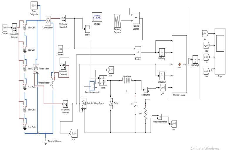
www.ijcrt.org © 2021 IJCRT | Volume 9, Issue 4 April 2021 | ISSN: 2320-2882

During Ton : During Toff :

In this mode inductor is charges fully and acts as short In this mode the stored energy will be dissipated at
circuit at the final state. The FD is reverse bias so it
 load, the FD will be forward bias and inductor will
inactivate as shown in black colour. The capacitor
 be replaced with current source. The voltage drop
connected across load will makes output voltage stable(but
not fully) across FD and inductor (but not for practical case)
 −

 Apply KCL at capacitor node
i(t) = (1 − ɼ ) here ɼ = sec IL = Ic + Io

 Ic(off) = IL – Io same as the current in ON mode
i(∞) = steady state current
 By KVL of path FD, inductor, load
VL(on) = VS –Vo where VS , Vo are source output voltages VL(off) +VFD +Vo = 0 ⸪ VFD = 0
 respectively VL(off) = - Vo
Ic(on) = IL - Io Where Il ,Io are inductor, output voltages
 respectively

Assuming Io is continuous
 In OFF mode VL(off) = - Vo, it does not mean that the voltage is switched to – ve plane, it mean that voltage
across load is negative for OFF mode the net voltage is resultant of both ON & OFF modes. Voltage – Sec balance
method which gives relation between source voltage (VS), load voltage or output voltage (Vo) and Duty cycle
 Vl(on)*TON + VL(off)* TOFF = 0
 (VS –Vo)* TON + (- Vo)* TOFF =0 ⸺⸺⸺ (A)

 T = TON + TOFF ; ⸪D= =
 +
 T = D*T + TOFF
 TOFF = T(1-D) ⸺⸺⸺ place in (A)
 (VS –Vo)* D*T + (- Vo)* (1-D)T = 0

 Vo= DVS
 0≤ ≤1

 Vo is always less than VS except at D = 1 (at this Vo= VS), so buck
 Converter is also called as Step down chopper due to above reason
 Similarly load current (Io) can be determined by using
 Current – Sec balance

 IJCRT2104577 International Journal of Creative Research Thoughts (IJCRT) www.ijcrt.org 4821
www.ijcrt.org © 2021 IJCRT | Volume 9, Issue 4 April 2021 | ISSN: 2320-2882

Ic(on) *TON + Ic(off) * TOFF = 0 capacitor were used, for low equivalent series resistance
(IL - Io ) *TON + (IL – Io)* TOFF = 0 (ESR) ceramic capacitors for ∆V is low as I was
(IL - Io ) *D*T + (IL – Io)* (1-D)T = 0 mentioned above also (capacitor selection). The ∆V will
 be depends on below
 Io= IL Ic = IL – Io ⸪ Q = CV; ∆Q = C*∆V
 ∆Q = Area of shaded in figure
Ripple in inductor current(∆I) : 1 ∆I ∆I
continuous conduction mode (CCM) is obtained by high = 2 ∗ 2 ∗ 2 => 8
value of inductor, the output wave form is ramped saw ∆Q ∆I VSD(1−D)
 = ∆V = 8 ⸪∆ I =
tooth as shown in figure, gives DC if we take average
for it. The sudden increase in load will decreases load
 D(1−D)
current will increases ∆I ∆ ∆V =
 ∅ 8 2
so, inductor value will decreases (L α )
 VL(on) = VS –Vo For what value of D we get max ∆V can be
 ∆V
 L

 = VS –Vo obtained by making = 0
 VSD(1−D)
 8LCf2
 = 0; by solving it we get D = 0.5
 L = VS -D VS
 ∗ it means that at D = 0.5 the voltage ripple is high
 D(1−D)T which was not preferable
 ∆I =
 Critical Inductance :
 D(1−D) It is the minimum value of inductor for which
 ∆I= inductor current or load current is just hold on
 Continuous conduction mode or IL(min) = o
Imax & Imin : At worst case IL(min) = o
 ∆I
ILmax = IL + 2
 ⸪ IL = Io IL -
 ∆IL
 =0 ⸪ Taken from previous result
 2
 ∆I D(1−D) ∗
 ILmax = Io +
 2
 Io - =0 ⸪ Io = =
 2
 ∗ D(1−D)
 ∆I = by solving
ILmin = IL - 2 2

 ∆I R(1−D)
 ILmin = Io - ∆ =
 2 2

 Noted that will increases by increasing R which
Source current : is not a favorable for continuous conduction
When we neglect the power loss at FD, Inductor (ie
 Critical Capacitance :
resistance free) and capacitor then
 The minimum value of capacitance for which output
Pout = Pin
 voltage is just continuous or ∆V = 0
VSIS = VoIo
 Under worst case Vc(min) = 0
 Vo∗Io ∆V
IS = Vo - 2 C = 0 ⸪ Vo = D*VS
 VS
 ∆VC D(1−D)
 D*VS - =0 ⸪ ∆VC =
Ripple in capacitor voltage (∆V) : 2 8 2
 D(1−D)
The sudden change in voltage across capacitor will also D*VS = by solving it
 16 2
affect on load voltage variation, if it is high then the R(1−D)
output will not be a stable which makes to place costly (1−D) 1 Where =
 ∆ = = 2
filter circuit for proper DC output, practically ∆V is less 16 2 8fR

compare to ∆I, however ∆V will depends on type of = Noted that will decreases by increasing R

 which is not a favorable for continuous conduction

 IJCRT2104577 International Journal of Creative Research Thoughts (IJCRT) www.ijcrt.org 4822
www.ijcrt.org © 2021 IJCRT | Volume 9, Issue 4 April 2021 | ISSN: 2320-2882

 Charging the battery with boost convertor :
 This is a kind of convertor which gives high output voltage than input voltage and also known as step up chopper .A
 high speed on/off semi conductor switch, MOSFET was connected across source, the rating of MOSFET is high
 compared to buck converter as inductor is connected in series with source, the sudden change in current will be
 opposed by inductor, under steady state inductor is short circuited ,under this condition if turnoff MOSFET thus we
 need highly rated MOSFET in order to neglect spark . In this converter the source is connected to load in both OFF
 & ON modes, apart from this the charged energy of inductor during ON mode will also contribute voltage to load
 during OFF, by this reason we will get voltage which is higher than input
 Calculations for devices used in convertor and maximum operating Duty cycle:
 Maximum duty cycle is essential for operate an convertor(Particularly in boost & buck boost) to minimize
 ripples at output and switching rms and average currents which causes to raise switching losses.
 0
 ∆Vc = ; here Io = output current

 I(sw)rms = 1−
 √ ; f = frequency of operation in herz

 I(sw)avg = 1−
 c = capacitance in faraday
 By the above parameters which are proportional to duty cycle and switching losses are depends on duty cycle i.e
 switching increases by increasing duty cycle
 (min)
 So maximum operation duty cycle Dmax = 1 -

 The output voltage for boost converter = Vo =(1− )

 D= place it in above equation
 +

 Vo = by solving it Boost converter [14]
 1−
 +
 ∗ 1
 Vo =
 shows that Vo α
 i.e, output voltage is increase while decrease in and at constant T , if
 >> in other words with less we can achieve more voltage at output

During Ton : During Toff :

After reaching steady state inductor will short circuited The un activated MOSFET is shown in black colour, in
and it is the moment that can store maximum energy by this mode both source and inductor will contribute
inductor ,although diode is forward bias the current voltage to load so, net output voltage is higher than input
produced by source (if load act as source diode will be as well output of buck converter. The capacitor
in reverse bias)will choose low resistance path (through connected across load will gives stable output, but
MOSFET), thus Load current(Io) equal to zero (for current is less compare to input current and output
resistive load) so Iin > Io, this is the another advantage current incase of buck converter, this is main reason of
that Io is low if using it for battery charging which achieves periodic

 − charging
i(t) = (1 − ɼ ) here ɼ = sec Apply KVL in path source, inductor and load

i(∞) = steady state current VS – VL – VO = 0
VS – VL(on) = 0 ; VL(on) = VS VL = VS – Vo
Ic(on) = - Io (initially we assumed that Io as positive but Apply KCL at capacitor node
 Load is contributing current so polarity is –ve) Ic(off) = IL - Io

 IJCRT2104577 International Journal of Creative Research Thoughts (IJCRT) www.ijcrt.org 4823

www.ijcrt.org © 2021 IJCRT | Volume 9, Issue 4 April 2021 | ISSN: 2320-2882

 Imax & Imin :
 ∆I
 ILmax = IL + 2
 ⸪ IL = (1− )
 ∆I
 ILmax = Io +
 2

 ∆I
 ILmin = IL - 2
 ∆I
 ILmin = Io -
 2

 Source current :
 When we neglect the power loss at FD, Inductor (i.e.
Voltage – Sec balance method which gives relation resistance free) and capacitor then
between source voltage (VS), load voltage or output Pout = Pin
voltage (Vo) and Duty cycle VSIS = VoIo
Vl(on)*TON + VL(off)* TOFF = 0
 Vo∗Io
VS * TON + (VS - Vo)* TOFF =0 ⸺⸺⸺ (A) IS =
 VS
T = TON + TOFF ; ⸪ D = + =

 Ripple in capacitor voltage (∆V) :
T = D*T + TOFF
 During ON condition either capacitor feed energy to
TOFF = T(1-D) ⸺⸺⸺ place in (A)
 load
VS * D*T + (VS- Vo)* (1-D)T = 0
 or load (Battery) supply energy to capacitor, assume
 that capacitor is feeding
 Vo= (1− ) 0≤ ≤1
 Ic = - Io
We can also derive above relation using Vo is always Io
greater than VS except at D = 1 (at this Vo= VS), so boost C* = - Io => dV = dt
converter is also called as Step Up chopper due to above Apply integration on both sides
reason. Similarly load current (Io) can be determined by Ic
using Current – Sec balance ∫ = ∫0

Ic(on) *TON + Ic(off) * TOFF = 0
Io *TON + (IL – Io)* TOFF = 0 Here we have applied as lower limit and as
Io *D*T + (IL – Io)* (1-D)T = 0 by solving this upper limit, due to capacitor is discharging as capacitor
 is acting as source
 Io
 IL= - = - *DT by taking - common
 (1− )
 Io
 ∆V = ∆V = *D
Note:
(a) In boost converter ≠ IL where as in buck converter Here ∆V is depends on Io where as in buck converter
 Io= IL it depends on Vs .Here ripple is proportional to duty
(b)I have already mentioned different parameters at buck cycle (D), so D at max ripple occurs will not exist.
 portion, over here I am just derive Critical Inductance:
Ripple in inductor current(∆I) : As I mentioned Critical inductance already
Since inductor charges for both modes in this converter ∆I
 IL - L = 0 ⸪ Taken from previous result
∆I is lesser than the ∆I of buck converter. During TON IL 2

will raises linearly, then decreases linearly TOFF , due
 (1− )
 = 2∗ ⸪ Io = =
 (1− )
reason of adding the load impedance as well, results saw

tooth waveform as in figure = 2 by solving
 (1− )2
 VL(on) = VS

L = VS RD(1−D)2

 ∆ = Icrt of boost < Lcrt of buck,
L ∗ = VS 2

 V D
 ∆ I =
 S

 IJCRT2104577 International Journal of Creative Research Thoughts (IJCRT) www.ijcrt.org 4824
www.ijcrt.org © 2021 IJCRT | Volume 9, Issue 4 April 2021 | ISSN: 2320-2882
Critical Capacitance : you see the duty cycle in both cases in calculations
Under worst case Vc(min) = 0 part, it was same ,we have to observe the output
∆VC
voltage in both converters at same duty cycle,
Vo - = 0 ⸪ Vo = Vc another question raises that converters at different duty
2
∆V Io cycles as mentioned in title, as we know that solar panel
Vo = 2 C ⸪ ∆VC = *D can’t provide continuous voltage due to temperature
Io∗ D Vo variations ,moisture conditions, mist etc .In order to
Vo = ⸪ Io = achieve maximum power we used an electronic device
2
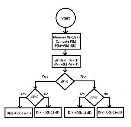
D called Maximum Power Point Tracker (MPPT) which
∆ = was operated on algorithm shown in figure. This module
2
= will tends to check the condition of = 0, the point at
Noted that will decreases by increasing R which is which maximum power flow, to satisfy this condition
not a favorable for continuous conduction and stability the variations will takes place in duty cycle(we had taken
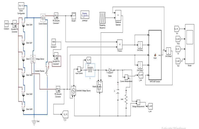
Parameters calculations for Buck converters : dD=0.05),thus the converter is operating in different
Let’s take VS = 12v; D = 0.45; ∆V = 0.5%; f = 40000 Hz duty cycles in order to flow maximum power from
Load = R =10 ohm, Solar radiations = 1000 w/m2 source to load. We did MATLAB simlink based on the
Parameter Formula Value algorithm called Perturb and Observe algorithm as
Inductance R(1−D) shown in below figure.
125% { 2 }
86*10-6 H Buck converter :
Capacitance (1−D)
8 2 100*10-6 F
Output Voltage D*VS
5.4V
Parameters calculations for Boost converters :
Let’s take VS = 12v; D = 0.45; ∆V = 0.5%; f = 40000 Hz
Load = R =10 ohm, Solar radiations = 1000 w/m2
Parameter Formula Value
RD(1− ) 2
Inductance 125%{ }
2 21.269*10-6 H
Capacitance × (min)
×∆ 225*10-6 F
Output Voltage
(1− )
21.818 V
Algorithm for MPPT
Boost converter :
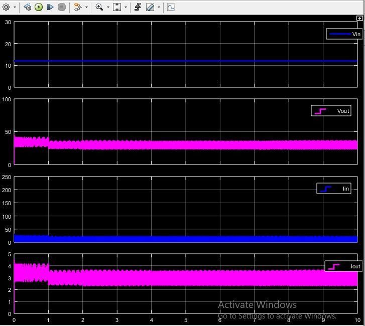
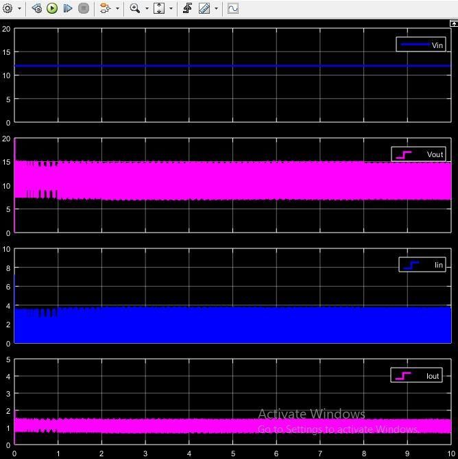
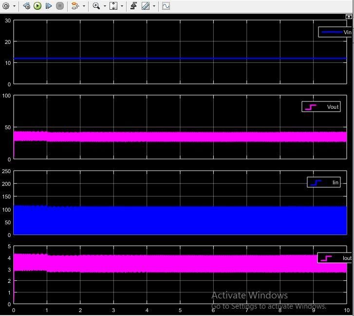
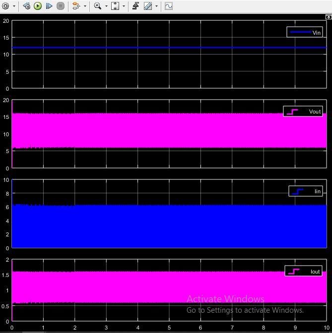
IJCRT2104577 International Journal of Creative Research Thoughts (IJCRT) www.ijcrt.org 4825www.ijcrt.org © 2021 IJCRT | Volume 9, Issue 4 April 2021 | ISSN: 2320-2882 Output of Buck converter at Critical Inductance(1): Output of Boost converter at Critical Inductance(3): Output of Boost converter at Inductance of 200 µH (4) : Output of Buck converter at Inductance of 200 µH (2): By the above waveforms, the Vo>Io ,due to large By observing above, placing high inductance had made the current flow through inductor under short circuit TON Io continuous with less ripple and by gradually increasing mode. If we increase inductance the Iin decreases, due to the inductance (up to certain value) the Io> Iin and Vo
www.ijcrt.org © 2021 IJCRT | Volume 9, Issue 4 April 2021 | ISSN: 2320-2882

Conclusion: [10] Smith, K.A.; Rahn, C.D.; Wang, C.Y. Model-based
By this paper authors analyzed various parameters of electrochemical estimation and constraint management for
converters before going to design them , the results were pulse operation of lithium ion batteries. IEEE Trans. Control.
 Syst. Technol. 2010, 18, 654–663.
tested using MATLAB-Simlink software at different values
 [11] https://www.solaronline.com.au/solar_system_basics
of parameters. This paper compared between charging with [12]https://batteryuniversity.com/learn/article/equalizingcharge
buck and boost converters, it explained removal of sulfation [13]https://components101.com/articles/buck-converter-
at electrodes by supplying power in such a way at high basics-working-design-and-operation
voltage low current by using boost converters. The periodic [14]https://components101.com/articles/boost-converter-
charging was achieved using boost converter, so With help basics-working-design
of this charge controller authors utilized the solar in [15]http://electricaltopics.blogspot.com/2014/10/charging-of-
efficient way and extend the lifetime of battery as well. lead-acid-battery.html
Placing high value inductor will in increases continuity with [16]https://www.embitel.com/automotive-
less ripples, another advantage of using high inductor rather insights/understanding-embedded-electronics-behind-solar-
 based-charging-of-electric-vehicles
than critical inductance is decrease the short circuit current
in case of boost converter during TON mode, it is similar as
minimize the abnormal current flow in alternator during
fault condition. In this paper the MATLAB-Simlink done
using algorithm called P&O algorithm for MPPT, which
contributes constant maximum power to load by satisfying
 1 ∆
 = 0 and operated at load line = in i-v
 ∆
characteristics. We can isolate between load and PV module
by converter is acting as isolator (only in buck converter)
References:
[1] Jaw-Kuen Shiau and Chien-Wei Ma “Li-Ion Battery Charging
with a Buck-Boost Power Converter for a Solar Powered Battery
Management System”, journal of Energies 2013, 6, 1669-1699;
doi:10.3390/en6031669
[2] Ahmad H. Sabry, Dr Wan Zuha Wan Hasan Prof. Dr. Mohd
Zainal, Dr. Mohd. Amran, Dr. Suhaidi B. Shafie ” Alternative
Solar-Battery Charge Controller to Improve System Efficiency.
TransTechPublications,Revised:doi:10.4028/www.scientific.net/
AMM.785.156
[3] Brigitte Hauke “Basic Calculation of a Boost Converter's
Power Stage”, Texas Instruments, SLVA372C–November 2009–
Revised January 2014
[4] M. Lokesh Reddy, P.J.R. Pavan Kumara, S. Aneel Manik
Chandra, T. Sudhakar Babu, N. Rajasekara. “Comparative study
on charge controller techniques for solar PV system,
1stInternational Conference on Power Engineering, Computing
and Control, PECCON-2017, 2-4 March 2017, VIT University,
Chennai Campus
[5] JAW-KUEN SHIAU, Member of IEEE ,DER-MING MA,
PIN-YING YANG, GENG-FENG WANG, JHIJ HUA GONG
Tamkang University, ” Design of a Solar Power Management
System for an
Experimental UAV”, IEEE Log No. T-AES/45/4/935097
[6] Priyabrata Shaw”Modelling and analysis of an analogue
MPPT based PV battery charging system utilising dc–dc boost
converter” ISSN 1752-1416 doi: 10.1049/iet-rpg.2018.6273
[7] Malay Bhunia and Rajesh Gupta” Voltage Regulation of
Stand-Alone Photovoltaic System using Boost SEPIC Converter
with
Battery Storage System” DOI:10.1109/SCES.2013.6547540
[8] Gao, L.; Liu, S.; Dougal, R.A. Dynamic lithium-ion battery
model for system simulation. EE Trans. Compon. Packag.
Technol. Technol. 2002, 25, 495–505.
[9] Lee, S.; Kim, J.; Lee, J.; Cho, B.H. State-of-charge and
capacity estimation of lithium-ion battery using a new open-
circuit voltage versus state-of-charge. J. Power Sources 2008,
185, 1367–1373.

 IJCRT2104577 International Journal of Creative Research Thoughts (IJCRT) www.ijcrt.org 4827
You can also read