3 Axis G Force Datalogger - Model VB300 User's Guide
←
→
Page content transcription
If your browser does not render page correctly, please read the page content below
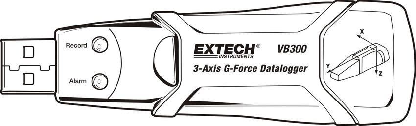
User's Guide

3‐Axis G‐Force Datalogger

Model VB300
Introduction
Congratulations on your purchase of the VB300 G‐Force Datalogger. The Model VB300
can measure and record shock and vibration (acceleration) readings over its ± 18g
measurement range. This device will record 3‐axis g‐force and related peaks to provide
a history of shock and vibration conditions. The real time clock provides time stamps
for all data.
The user can easily configure the logging rate, high/low alarm and start‐mode, and
download the stored data by plugging the VB300 into a PC's USB port and running the
supplied PC software. Measurement data can be plotted, printed and exported for use
with other applications such as word processors and spreadsheets. The data logger is
supplied with a long‐life 1000 hour lithium battery.
The VB300 memory uses a 4MB Flash device that can hold 168042 Normal recordings
or 112028 Motion Detection recordings per axis.
This meter is shipped fully tested and calibrated and, with proper use, will provide
years of reliable service.
Features
Records 3‐axis g force shock and vibration
Built‐in accelerometer
Measures static and dynamic acceleration
Real time operation (time stamped data)
Normal and Motion detection mode
Real time FFT frequency analysis
Manual and Automatic datalogger start modes
Selectable data sampling rate
Status Indication via Red and Green LEDs
USB Interface for Set‐up and Data Download
User‐Programmable motion thresholds
Long battery life ‐ 1000 hours
2 VB300-en-US_V1.4 8/14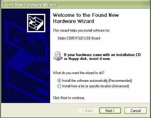
Description
Meter Description
1. USB connector
2. RECORD LED
3. ALARM LED
4. Datalogger Start / Stop Button
5. Axis reference diagram
Note: Battery compartment access screws (2) located on rear of unit. Refer to the battery installation
section for further details.
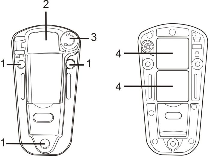
Pedestal Mount Description
1. Mounting screw holes
2. Swivel latch
3. Swivel latch lock
4. Mounting magnets
FRONT VIEW REAR VIEW
3 VB300-en-US_V1.4 8/14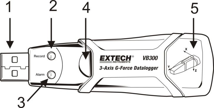
Mounting the VB300
The VB300 fits securely in the supplied mounting pedestal. Unscrew the pedestal latch
and snap the VB300 into the pedestal. Secure the latch and follow one of the mounting
methods below. There are three mounting methods for affixing the pedestal to the area
under test:

    1.   Magnetically: Powerful magnets are built into the rear of the pedestal

    2.   Adhesive: Use glue (not supplied) to affix the pedestal to the area under test

    3.   Screws: Three mounting holes are provided on the pedestal for screw mounting
         (screws not supplied)

LED Status Indication
         LED                 Description                               Action
         Record Alarm
                             LEDs not flashing
                               ‐No logging in process

                                ‐No battery found                      ‐ Install battery

                                ‐Battery completely                    ‐ Replace the battery and
                             discharged                                  download the data
                             Green single flash every 10 sec.          Press and hold the
                             *                                         datalogger Start/Stop
                               ‐Logging, no alarm**                    button on the VB300 until
                                                                       the red LED flashes four
                                                                       times to stop logging
                             Red single flash every 30 sec. *          If the unit is datalogging it
                               ‐Low Battery                            will stop automatically.
                                                                       The Data will NOT be lost.
                                                                       Replace battery
                             Red and Green alternating
                             flashing every 60 seconds;
                             ‐Datalogger memory is full                ‐Download data
     *   To save power, the VB300’s LED flashing cycle can be changed via the supplied software.
     ** To save power, alarm LEDs for temperature can be disabled via the supplied software.
     NOTE: When the battery is low, all operations will be disabled automatically.
     NOTE: Logging automatically stops when the battery weakens (logged data will be retained).

                                                   4                          VB300-en-US_V1.4 8/14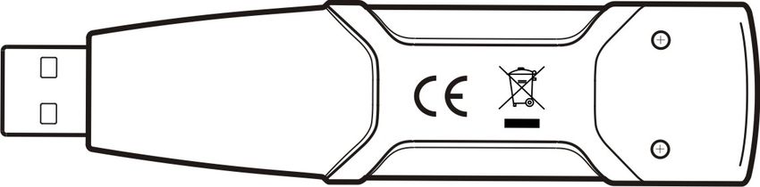
Datalogging Software Program

INSTALLING THE DATALOGGER SOFTWARE

Install the supplied WindowsTM PC Datalogger Software by placing the supplied program
disk in the PC’s CD‐ROM drive. If the installation program does not automatically open
and provide on‐screen prompts (as shown in diagram below), open and browse the
CD‐ROM drive, then find and double‐click on the SETUP.EXE file included on the program
disk. Follow the on‐screen prompts as shown below to complete the installation.

                                                          Before       running     the
                                                          datalogger software, please
                                                          connect the VB300 to the
                                                          PC and install the USB
                                                          Driver software as described
                                                          in the next section.

                                          5                     VB300-en-US_V1.4 8/14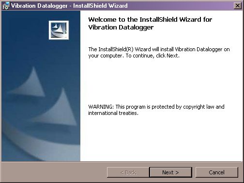
INSTALLING THE USB DRIVER
The PC will prompt for the USB Driver installation immediately after the main software
program is installed. A window similar to the one shown below will appear to prompt for
the installation. Simply click INSTALL to continue.

To install the driver manually, plug the VB300 into an available USB port on the PC. If this
is the first time that the VB300 is connected to the particular port on the PC, the
following screen will appear:

Make sure the program disk is still in the PC CD‐ROM drive. Select the ‘recommended’
installation and follow the on‐screen prompts to complete the driver installation. If this
is a repeat connection of the VB300 to the USB port, the driver installation process will
be automatically skipped.
                                             6                      VB300-en-US_V1.4 8/14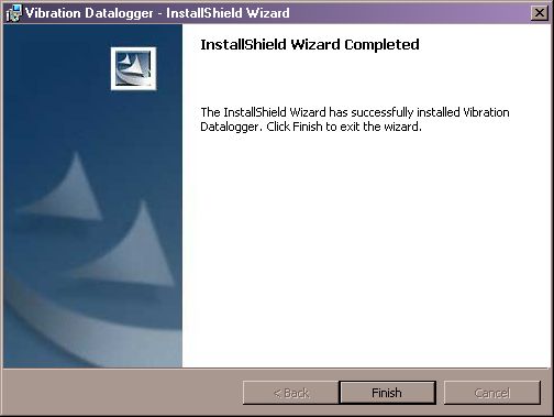
RUNNING THE DATALOGGER SOFTWARE

With the VB300 inserted in the PC’s USB port, double‐click the program icon (located on
the desktop) to launch the program. The main software screen will appear.

Instructions for using the Datalogger Software are contained in the HELP Utility available
from the HELP menu in the software program. Please read the HELP Utility thoroughly in
order to fully understand the software and the related functionality of the VB300.

Note:   When the VB300 is connected to the USB port, its battery discharges at a higher
        rate than normal. To conserve battery life, do not leave the VB300 connected to
        the USB port for a prolonged period of time.

                                            7                      VB300-en-US_V1.4 8/14
Basic Datalogger Operation
This section covers only the starting and stopping of the Datalogger’s recording
functions. All other information is provided in the HELP utility within the software
program.
1. Configure the Datalogger’s sample rate, motion detection threshold, record mode,
LED flash cycle and more using the supplied software program. Refer to the
instructions included in the software program’s HELP utility to configure the
datalogger and to otherwise use the software.
2. If AUTO start is selected in the software, the datalogger will begin logging data the
moment the software window is closed. If MANUAL is selected, press and hold the
datalogger start/stop button until the green LED flashes; the datalogger LED
flashes periodically (flash interval time selectable in software) indicating that the
datalogger is recording.
3. To stop datalogging, press and hold the start/stop button while the unit is
datalogging. The red LED will quickly flash indicating that datalogging has stopped.
Refer to the LED status table earlier in this manual for interpreting the LED flash
information.
4. Refer to the software HELP utility for transferring the data from the logger to the
PC.
1g OFFSET
The axis (or combination of axis) parallel to the earth surface will indicate the 1g force
related to gravitational force.
5g
4g
3g
2g
1g
0g
-1g
X Y Z
8 VB300-en-US_V1.4 8/14Specifications
Acceleration Range: ± 18g Resolution: 0.00625g
Accuracy ± 0.5g
Frequency Range 0 to 60Hz
Datalog Memory 4MB Flash stores 168042 Normal recording records or
112028 Motion Detection records per axis.
Logging rate Selectable sampling interval: From 50ms up to 24 hours
Data format Time stamped peak acceleration and freefall; Average and
Peak Vector sums
Computer PC interface USB
Hardware requirements 8MB RAM; 2MB Hard Drive space for software program;
USB jack
System requirements WindowsTM XP, VISTA, WindowsTM 7 (32 and 64 bit)
Operating temperature 32 to 104oF (0 to 40oC)
Storage temperature 0 to 140oF (‐10 to 60oC)
Battery type 3.6V Lithium (1/2 AA) 1.0Ah (Saft LS‐14250 or equiv)
Power consumption 1mA (typical, while recording); < 15µA while idling
Battery life 1000 hours approx.
Dimensions/Weight 3.7 x 1.1 x 0.8” (95 x 28 x 21mm) / 6oz (172g)
9 VB300-en-US_V1.4 8/14Battery Replacement
The VB300 does not lose its stored readings when the battery expires or when the
battery is replaced. The data logging process will however be stopped and cannot be
re‐started until the battery has been replaced and the logged data has been
downloaded to PC.
The battery life is rated for approx. 1000 hours. If in doubt, replace the battery before
logging critical data. Use only 3.6V lithium batteries. Before replacing the battery,
remove the datalogger from the PC.
Note: When the VB300 is connected to the USB port, its battery discharges at a
higher rate than normal. To conserve battery life, do not leave the VB300
connected to the USB port for a prolonged period of time.
1. Remove the two Phillips screws identified with the two smaller arrows in the
diagram below.
2. Slide the battery compartment cover in the direction of the larger arrow.
3. Replace the battery with one of the same type (3.6V lithium, ½ AA 1.0Ah, Saft
LS‐14250 or equiv).
4. Close the battery compartment and tighten with the two screws.
WARNING: Handle lithium batteries carefully, observe warnings on battery casing.
Dispose of in accordance with local regulations.
10 VB300-en-US_V1.4 8/14Warranty
FLIR Systems, Inc. warrants this Extech Instruments brand device to be free of defects in parts and workmanship for one year
from date of shipment (a six month limited warranty applies to sensors and cables). If it should become necessary to return the
instrument for service during or beyond the warranty period, contact the Customer Service Department for authorization. Visit
the website www.extech.com for contact information. A Return Authorization (RA) number must be issued before any product is
returned. The sender is responsible for shipping charges, freight, insurance and proper packaging to prevent damage in transit.
This warranty does not apply to defects resulting from action of the user such as misuse, improper wiring, operation outside of
specification, improper maintenance or repair, or unauthorized modification. FLIR Systems, Inc. specifically disclaims any implied
warranties or merchantability or fitness for a specific purpose and will not be liable for any direct, indirect, incidental or
consequential damages. FLIR’s total liability is limited to repair or replacement of the product. The warranty set forth above is
inclusive and no other warranty, whether written or oral, is expressed or implied.
Calibration, Repair, and Customer Care Services
FLIR Systems, Inc. offers repair and calibration services for the Extech Instruments products we
sell. NIST certification for most products is also provided. Call the Customer Service Department for
information on calibration services available for this product. Annual calibrations should be
performed to verify meter performance and accuracy. Technical support and general customer
service is also provided, refer to the contact information provided below.
Support Lines: U.S. (877) 439‐8324; International: +1 (603) 324‐7800
Technical Support: Option 3; E‐mail: support@extech.com
Repair & Returns: Option 4; E‐mail: repair@extech.com
Product specifications are subject to change without notice
Please visit our website for the most up‐to‐date information
www.extech.com
FLIR Commercial Systems, Inc., 9 Townsend West, Nashua, NH 03063 USA
ISO 9001 Certified
Copyright © 2014 FLIR Systems, Inc.
All rights reserved including the right of reproduction in whole or in part in any form
www.extech.com
11 VB300-en-US_V1.4 8/14Garantie
FLIR Systems, Inc. garantit que cet appareil Extech Instruments est exempt de défauts matériaux et de fabrication pendant un
an à partir de la date d’envoi (une garantie limitée de six mois s’applique aux capteurs et aux câbles). Si le renvoi de l’appareil
pour réparation devient nécessaire durant ou après la période de garantie, contactez le service client pour autorisation. Pour
obtenir les coordonnées, visitez le site Web suivant : www.extech.com. Un numéro d’autorisation de retour (AR) doit être délivré
avant tout retour de produit. L’expéditeur prend à sa charge les frais d’expédition, le fret, l’assurance et l’emballage correct de
l’appareil afin de prévenir toute détérioration durant le transport. Cette garantie ne s’applique pas aux dommages imputables à
l’utilisateur, tels que l’usage impropre ou abusif, un mauvais câblage, une utilisation non conforme aux spécifications, un
entretien ou une réparation incorrecte, ou toute modification non autorisée. FLIR Systems, Inc. déclinera spécifiquement toute
garantie ou qualité marchande ou aptitude à l’emploi prévu, et ne sera en aucun cas tenu responsable pour tout dommage
conséquent, direct, indirect ou accidentel. La responsabilité totale de FLIR est limitée à la réparation ou au remplacement du
produit. La garantie définie ci‐dessus est inclusive et aucune autre garantie, écrite ou orale, n’est exprimée ou implicite.
Calibrage, réparation et services après‐vente
FLIR Systems, Inc. offre des services de calibrage et de réparation pour les produits Extech
Instruments que nous commercialisons. Nous fournissons également une certification NIST pour la
plupart des produits. Contactez notre service client pour toute information sur les services de
calibrage disponibles pour ce produit. Un calibrage doit être effectué chaque année pour vérifier
les performances et la précision du mètre. Nous offrons également une assistance technique et un
service à la clientèle. Veuillez vous reporter aux coordonnées fournies ci‐dessous.
Lignes d’assistance: États‐Unis (877) 439‐8324; international: +1 (603) 324‐7800
Service d’assistance technique : Option 3 ; E‐mail : support@extech.com
Réparations et retours : Option 4 ; E‐mail : repair@extech.com
Les spécifications produit sont sujettes à modifications sans préavis.
Pour les toutes dernières informations, veuillez visiter notre site Web.
www.extech.com
FLIR Commercial Systems, Inc., 9 Townsend West, Nashua, NH 03063 USA
Certifié ISO 9001
Copyright © 2014 FLIR Systems, Inc.
Tous droits réservés, y compris la reproduction partielle ou totale sous quelque forme que ce soit.
www.extech.com
12 VB300-en-US_V1.4 8/14Garantía
FLIR Systems, Inc., garantiza este dispositivo marca Extech Instruments para estar libre de defectos en partes o mano de obra
durante un año a partir de la fecha de embarque (se aplica una garantía limitada de seis meses para cables y sensores). Si fuera
necesario regresar el instrumento para servicio durante o después del periodo de garantía, llame al Departamento de Servicio a
Clientes para obtener autorización. Visite www.extech.com para Información de contacto. Se debe expedir un número de
Autorización de Devolución (AD) antes de regresar cualquier producto. El remitente es responsable de los gastos de embarque,
flete, seguro y empaque apropiado para prevenir daños en tránsito. Esta garantía no se aplica a defectos resultantes de las
acciones del usuario como el mal uso, alambrado equivocado, operación fuera de las especificaciones, mantenimiento o
reparación inadecuada o modificación no autorizada. FLIR Systems, Inc., rechaza específicamente cualesquier garantías
implícitas o factibilidad de comercialización o idoneidad para cualquier propósito determinado y no será responsable por
cualesquier daños directos, indirectos, incidentales o consecuentes. La responsabilidad total de FLIR está limitada a la reparación
o reemplazo del producto. La garantía precedente es inclusiva y no hay otra garantía ya sea escrita u oral, expresa o implícita.
Servicios de calibración, reparación y atención a clientes
FLIR Systems, Inc., ofrece servicios de reparación y calibración para los productos que vendemos
de Extech Instruments. Además ofrecemos certificación NIST para la mayoría de los productos.
Llame al Departamento de Servicio al Cliente para solicitar información de calibración para este
producto. Para verificar el funcionamiento y precisión se debe realizar la calibración anual. Además
se provee Soporte Técnico y servicios generales al cliente, consulte la información de contacto en
seguida.
Líneas de soporte: EE.UU. (877) 439‐8324; Internacional: +1 (603) 324‐7800
Soporte Técnico Opción 3; correo electrónico: support@extech.com
Reparación / Devoluciones: Opción 4; correo electrónico: repair@extech.com
Las especificaciones del producto están sujetas a cambios sin aviso
Por favor visite nuestra página en Internet para la información más actualizada
www.extech.com
FLIR Commercial Systems, Inc., 9 Townsend West, Nashua, NH 03063 USA
Certificado ISO 9001
Copyright © 2014 FLIR Systems, Inc.
Reservados todos los derechos, incluyendo el derecho de reproducción total o parcial en cualquier medio
www.extech.com
13 VB300-en-US_V1.4 8/14You can also read


