Design of a 4-Seat, General Aviation, Electric Aircraft - SJSU ...
←
→
Page content transcription
If your browser does not render page correctly, please read the page content below
San Jose State University
SJSU ScholarWorks
Master's Theses                                                                                  Master's Theses and Graduate Research

Fall 2012

Design of a 4-Seat, General Aviation, Electric
Aircraft
Arvindhakshan Rajagopalan Srilatha
San Jose State University

Follow this and additional works at: https://scholarworks.sjsu.edu/etd_theses

Recommended Citation
Rajagopalan Srilatha, Arvindhakshan, "Design of a 4-Seat, General Aviation, Electric Aircraft" (2012). Master's Theses. 4248.
DOI: https://doi.org/10.31979/etd.rss9-mc3k
https://scholarworks.sjsu.edu/etd_theses/4248

This Thesis is brought to you for free and open access by the Master's Theses and Graduate Research at SJSU ScholarWorks. It has been accepted for
inclusion in Master's Theses by an authorized administrator of SJSU ScholarWorks. For more information, please contact scholarworks@sjsu.edu.
DESIGN OF A 4-SEAT, GENERAL AVIATION, ELECTRIC AIRCRAFT

                              A Thesis
                             Presented to
The Faculty of the Department of Mechanical and Aerospace Engineering
                      San José State University

                        In Partial Fulfillment
                  of the Requirements for the Degree
                          Master of Science

                                 by
                     Arvindhakshan Rajagopalan
                           December 2012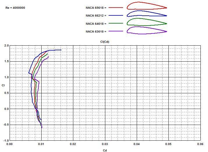
© 2012

Arvindhakshan Rajagopalan

ALL RIGHTS RESERVED
The Designated Thesis Committee Approves the Thesis Titled

     DESIGN OF A 4-SEAT, GENERAL AVIATION, ELECTRIC AIRCRAFT
                                       By
                            Arvindhakshan Rajagopalan

 APPROVED FOR THE DEPARTMENT OF MECHANICAL AND AEROSPACE
                       ENGINEERING

                        SAN JOSÉ STATE UNIVERSITY

                                 December 2012

Dr. Nikos Mourtos           Department of Mechanical and Aerospace Engineering
Dr. Periklis Papadopoulos   Department of Mechanical and Aerospace Engineering
Srikrishna S. Chittur       Aerodynamics Engineer, Brayton Energy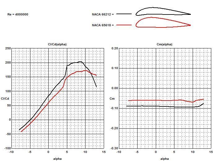
ABSTRACT

     DESIGN OF A 4-SEAT, GENERAL AVIATION, ELECTRIC AIRCRAFT

                            By Arvindhakshan Rajagopalan

       Range and payload of current electric aircraft is limited primarily due to low

energy density of batteries. However, recent advances in battery technology promise

storage of more than 1 kWh of energy per kilogram of weight in the near future. This

kind of energy storage makes possible the design of an electric aircraft comparable to,

if not better than existing state-of-the art general aviation aircraft powered by internal

combustion engines. This thesis explores through parametric studies the effect of lift-

to-drag ratio, flight speed, and cruise altitude on required thrust power and battery

energy and presents the conceptual and preliminary design of a four-seat, general

aviation electric aircraft with a takeoff weight of 1750 kg, a range of 800 km, and a

cruise speed of 200 km/h. An innovative configuration design will take full

advantage of the electric propulsion system, while a Lithium-Polymer battery and a

DC brushless motor will provide the power. Advanced aerodynamics will explore the

greatest possible extend of laminar flow on the fuselage, the wing, and the empennage

surfaces to minimize drag, while advanced composite structures will provide the

greatest possible savings on empty weight. The proposed design is intended to be

certifiable under current FAR 23 requirements.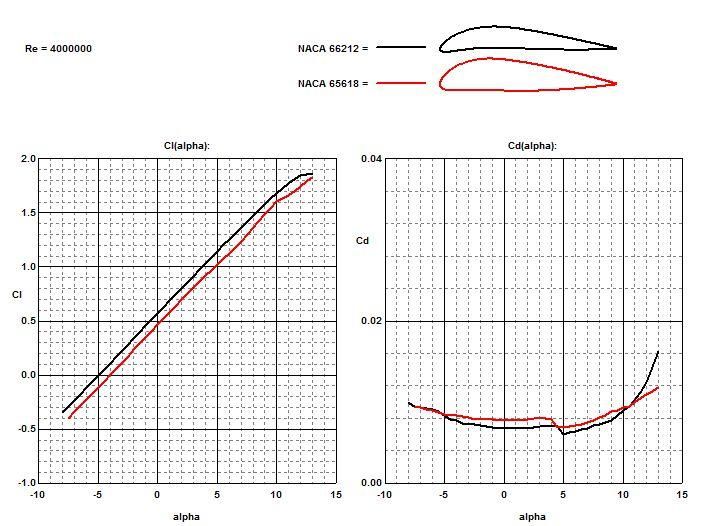
ACKNOWLEDGMENTS

       This thesis is a true success because of the never ending love and support from

my parents, brother, relatives, teachers and friends.

       First, I would like to thank Professor Nikos Mourtos for his support and

guidance from the first day of my master’s degree. His technical knowledge,

simplicity, humbleness, and cheerful attitude make him the most respectful person. I

feel so proud to get him as my advisor. His advice and support could never be

explained by mere words. I am so grateful to him for helping me throughout my

master’s degree. This thesis would have never been possible without his

encouragement and guidance.

       Second, I thank my parents and brother for their unconditional love and

support, and their endless confidence in me. Every accomplishment in my life would

have never been possible without them.

       Finally, I would like to thank my relatives and friends who supported me for

my education here in the United States. I am currently in this position only because

of their blessings and wishes.

                                            v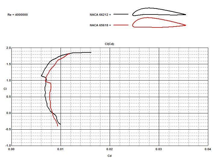
TABLE OF CONTENTS

LIST OF FIGURES ................................................................................................................................................. vii
LIST OF TABLES .................................................................................................................................................. viii
1.0          INTRODUCTION ....................................................................................................................................... 1
2.0          THE ROLE OF ELECTRIC AIRCRAFT ................................................................................................... 2
3.0          EXISTING ELECTRIC AIRCRAFT DESIGNS ........................................................................................ 3
    3.1          ELECTRA ONE ..................................................................................................................................... 4
    3.2          YUNEEC E 430...................................................................................................................................... 5
    3.3          CRI-CRI ................................................................................................................................................. 6
    3.4          PIPISTREL TAURUS G2 ...................................................................................................................... 7
    3.5          PIPISTREL PANTHERA ....................................................................................................................... 8
    3.6          ANTARES H3 ........................................................................................................................................ 9
4.0          DESIGN REQUIREMENTS ..................................................................................................................... 10
5.0          PROPULSION TYPE SELECTION ......................................................................................................... 10
    5.1          ELECTRIC MOTOR CHARACTERISTICS ....................................................................................... 12
    5.2          PROPELLER CHARACTERISTICS ................................................................................................... 12
    5.3          BATTERY CHARACTERISTICS ....................................................................................................... 13
6.0          PRELIMINARY SIZING .......................................................................................................................... 14
    6.1          TAKEOFF WEIGHT ESTIMATION .................................................................................................. 14
    6.2          PERFORMANCE SIZING ................................................................................................................... 15
    6.3          SUMMARY OF PERFORMANCE SIZING ....................................................................................... 16
    6.4          BATTERY SIZING .............................................................................................................................. 17
7.0          PRELIMINARY DESIGN ........................................................................................................................ 20
    7.1          FUSELAGE LAYOUT ........................................................................................................................ 20
    7.2          ENGINE SELECTION AND DISPOSITION ...................................................................................... 21
    7.3          WING DESIGN .................................................................................................................................... 21
    7.4          WEIGHT AND BALANCE ANALYSIS ............................................................................................. 23
    7.5          LANDING GEAR ................................................................................................................................ 26
    7.6          EMPENNAGE ..................................................................................................................................... 26
    7.7          HIGH LIFT DEVICES ......................................................................................................................... 27
    7.8          AIRFOIL SELECTION ........................................................................................................................ 28
    7.9          DRAG POLAR ..................................................................................................................................... 32
10.0             PRELIMINARY DESIGN LAYOUT .................................................................................................. 34
11.0             CONCLUSION .................................................................................................................................... 35
REFERENCES ........................................................................................................................................................ 36

                                                                                   vi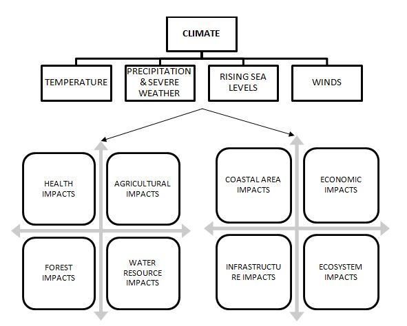
LIST OF FIGURES

Figure 1. Effect of Climate Change and its Consequences...................................................................... 1

Figure 2. Growth in Aviation-Related Pollutants by 2021. ..................................................................... 2

Figure 3. Electra One [15]. ...................................................................................................................... 4

Figure 4. Yuneec E 430 [16]. .................................................................................................................. 5

Figure 5. Cri-Cri [17]. ............................................................................................................................. 6

Figure 6. Pipistrel Taurus G2 [18]. .......................................................................................................... 7

Figure 7. Pipistrel Panthra [19]. .............................................................................................................. 8

Figure 8. Antares H3 [9].......................................................................................................................... 9

Figure 9. Performance Sizing Graph. .................................................................................................... 15

Figure 10. Fuselage Dimensions. .......................................................................................................... 20

Figure 11. Nose Mounted Engine. ......................................................................................................... 21

Figure 12. Wing specifications. ............................................................................................................. 23

Figure 13. Location of Various Components for Estimating the CG Location. .................................... 24

Figure 14. CG Excursion Diagram. ....................................................................................................... 25

Figure 15. Drag Polar Comparison of Various Naca 6-Series Airfoils. ................................................ 29

Figure 16. Lift and Drag Characteristics Comparison of Various Naca 6-Series Airfoils. ................... 29

Figure 17. Lift-To-Drag Ratio and Pitching Moment Comparison of Various Naca 6-Series Airfoils . 30

Figure 18. Comparison of the Drag Polars for the Naca 66212 and Naca 65618 Airfoils. ................... 30

Figure 19. Comparison of the Lift and Drag of the Naca 66212 and Naca 65618 Airfoils. .................. 31

Figure 20. Comparison of the L/D Ratio and Moment of the Naca 66212 and Naca 65618 Airfoils. .. 31

Figure 21. Preliminary Design Layout. ................................................................................................. 34

Figure 22. Electric Aircraft: Three View............................................................................................... 34

                                                                         vii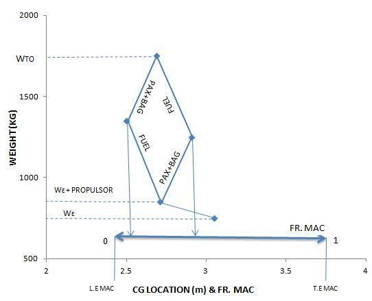
LIST OF TABLES

Table 1. Existing Electric Aircraft. .......................................................................................................... 3

Table 2. Electric Aircraft under Research. .............................................................................................. 3

Table 3. Electra One Specifications. ....................................................................................................... 4

Table 4. Yuneec E 430 Specifications. .................................................................................................... 5

Table 5. Cri-Cri Specifications. ............................................................................................................... 6

Table 6. Pipistrel Taurus G2 Specifications. ........................................................................................... 7

Table 7. Pipistrel Panthera Specifications. .............................................................................................. 8

Table 8. Antares H3 Specifications. ........................................................................................................ 9

Table 9. Fuel Cell Specifications........................................................................................................... 11

Table 10. Battery Specifications............................................................................................................ 11

Table 11. Comparison of Different Batteries. ....................................................................................... 13

Table 12. Summary of Performance Sizing. .......................................................................................... 16

Table 13. Effect of L/D over Thrust Power and Battery Energy. .......................................................... 18

Table 14. Effect of L/D over Specific Energy and Battery Mass. ......................................................... 19

Table 15. Estimation of Empty Weight CG. ......................................................................................... 24

Table 16. CG Estimation. ...................................................................................................................... 25

Table 17. Lift Coefficient Increments for Various Types of High Lift Devices................................... 27

Table 18. Preliminary Estimates of Cdo and e........................................................................................ 32

Table 19. Drag Coefficient and L/D Ratio for Different Aircraft Configurations. ................................ 33

                                                                      viii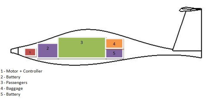
1.0   INTRODUCTION

      It is now recognized that emission of carbon, nitrogen oxides, halogens, and

other products from the burning of aviation fuel contributes to the climatic change we

have been experiencing (e.g., ozone layer depletion, air quality degradation) [1].

Furthermore, current airplane engines are noisy. According to GAO Report 2008,

aviation emissions contribute about 1% of the air pollution and 2.7% of the US gas

emissions. Although these percentages seem small, global air traffic is predicted to

increase at a rate of 20% by 2015 and 60% by 2030. Currently, global aircraft

emissions produce about 3.5% of the warming generated by human activity [2].

However, if unchecked, by 2021 the emissions will increase up to 90% from the

current level [2]. This negative impact on the environment can be reduced by

introducing more eco-friendly propulsion systems and suitable airplane designs. One

of the steps to achieve eco-aviation is designing an aircraft with an electric propulsion

system.

                  Figure 1. Effect of Climate Change and its Consequences.

                                             1
100
90
80
PERCENT INCREASE
70
60 HYDROCARBON
50
CARBON MONOXIDE
40
30 NITROGEN OXIDES
20 SULFUR OXIDES
10
0
POLLUTANTS
Figure 2. Growth in Aviation-Related Pollutants by 2021.
2.0 THE ROLE OF ELECTRIC AIRCRAFT
The advantages of electric motors (EM) compared to bio fuel are summarized
below.
Very light weight (45 lb for EM compared to 400 lb for ICE)
More power per unit weight
More efficient energy conversion (90-95% for EM compared to 20-25% for ICE)
Improved high altitude performance (higher ceiling as well as airspeed and climb
rate)
Noise reduction
High reliability and safety
Lower operating cost ($5-$10/h for EM, compared to $35-$50/h for ICE)
Easier maintenance
Low pollution
23.0 EXISTING ELECTRIC AIRCRAFT DESIGNS
Tables 1 and 2 summarize data on the propulsion types of electric aircraft. Table 1
refers to existing aircraft, whereas Table 2 presents data on aircraft currently under
research.
Table 1. Existing Electric Aircraft.
Company Name Type Propulsion
PC Aero Electra One 1 - Seat Electric Motor + Li Po Battery
Yuneec E 430 2 - Seat Electric Motor + Li Po Battery
EADS Cri-Cri 1 – Seat Electric Motor + Li Po Battery
Pipistrel Taurus Electro G2 2 – Seat Electric Motor
Boeing ------- 1 – Seat Electric Motor
Sikorsky Firefly Helicopter Electric Motor
Pipistrel Panthera 4 - Seat Electric Motor
Table 2. Electric Aircraft under Research.
Company Name Type Propulsion
Lange Aviation Antares 3 UAV Electric Motor + Fuel Cell
Yuneec E 1000 4-Seat Electric Motor + Li Po Battery
Flight Design ------ 4-Seat Electric Motor + Ice
3Figures 3-8 represent the existing electric aircraft while the tables 3-8 show the
performance characteristics and specifications of the aircraft [6 - 9].
3.1 ELECTRA ONE
The design of Electra One is shown in Figure 3. The specifications of the
aircraft are given in Table 3.
Figure 3. Electra One [15].
Table 3. Electra One Specifications.
Electric Motor
Power System
(Li-Polymer Battery)
Number of Seats 1
Maximum Weight 300 kg
Maximum Engine Power 16 KW
Maximum Range 400 Km
Maximum Endurance 3 hours
43.2 YUNEEC E 430
The design of Yuneec E 430 is shown in Figure 4. The specifications of the
aircraft are given in Table 4.
Figure 4. Yuneec E 430 [16].
Table 4. Yuneec E 430 Specifications.
Electric Motor
Power System
(Li-Polymer Battery)
Number of Seats 2
Maximum Weight 430 kg
Maximum Engine Power 40 KW
Maximum Endurance 2 Hours
53.3 CRI-CRI
The design of Cri-Cri is shown in Figure 5. The specifications of the aircraft
are given in Table 5.
Figure 5. Cri-Cri [17].
Table 5. Cri-Cri Specifications.
4 Electric Motors
Power System
(Li-Polymer Battery)
Number of Seats 1
Cruise Speed 110 km/h
Maximum Engine Power 22 KW
Maximum Speed 210 km/h
Maximum Endurance 30 min
63.4 PIPISTREL TAURUS G2
The design of Pipistrel Taurus G2 is shown in Figure 6. The specifications of
the aircraft are given in Table 6.
Figure 6. Pipistrel Taurus G2 [18].
Table 6. Pipistrel Taurus G2 Specifications.
Electric Motor
Power System
(Battery)
Number of Seats 1
Cruise Speed 110 km/h
Maximum Engine Power 40 KW
Maximum Range 200 km
Maximum Endurance 2h
73.5 PIPISTREL PANTHERA
The design of Pipistrel Panthera is shown in Figure 7. The specifications of the
aircraft are given in Table 7.
Figure 7. Pipistrel Panthra [19].
Table 7. Pipistrel Panthera Specifications.
Electric Motor
Power System
(Battery)
Number of Seats 4
Cruise Speed 218 km/h
Maximum Engine Power 145 KW
Maximum Range 400 km
Service Ceiling 4000 m
83.6 ANTARES H3
The design of Antares H3 is shown in Figure 8. The specifications of the
aircraft are given in Table 8.
Figure 8. Antares H3 [9].
Table 8. Antares H3 Specifications.
Electric Motor
Power System
(Fuel Cell)
Operation UAV
Maximum Speed 250 km/h
Maximum Engine Power 36 KW
Maximum Range >6000 km
Maximum Endurance >50 h
94.0 DESIGN REQUIREMENTS
The design requirements for the proposed aircraft are as follows.
General aviation, FAR 23 certifiable
4 passengers (including pilot)
Electrically powered
Range = 800 km
Cruise speed = 200 km / h
5.0 PROPULSION TYPE SELECTION
The following factors are taken into consideration in the selection of the
propulsion system:
1. Power density
2. Energy density
3. Safety
4. Cost
5. Reliability
A trade study was performed to decide the type of energy source, namely a battery
or a fuel cell. The battery and fuel cell characteristics needed to produce 135 hp in a
ground based electric vehicle are shown in Tables 9 and 10 [13]. Based on this
comparison, the best option is the battery due to its lower weight, volume, and cost.
Although the energy density of the fuel cell is higher than that of the battery, the
space occupied by the fuel cell is too large to be used in a 4 seat aircraft.
10Table 9. Fuel Cell Specifications.
Component Weight (Kg) Volume (Liters) Cost ($)
Fuel Tank 617 1182 23,033
3.2 kg
51 215 2,288
Storage Tank
Drive Train 53 68 3,826
Total 721 1465 29,147
Table 10. Battery Specifications.
Component Weight (Kg) Volume (Liters) Cost ($)
Li ion Battery 451 401 16,125
Drive Train 53 68 3,826
Total 504 469 19,951
The following sections explain the characteristics of motor and battery selection.
The lightest and most efficient devices have been chosen for the proposed design.
115.1 ELECTRIC MOTOR CHARACTERISTICS
A DC brushless motor is chosen because of its higher reliability and higher
torque at lower rpm. The brushless motor is purely inductive. Unlike a brushed
motor, there is no brush to replace, so the motor life depends mostly on the bearings.
5.2 PROPELLER CHARACTERISTICS
The desired characteristics of the propeller are for light weight and low noise
production for the desired level of thrust. Increasing the number of blades decreases
noise, but it also increases the structural weight and decreases blade efficiency. Each
blade rotates in the wake of a closely positioned blade as the number of blades
increases. Decreasing the number of blades requires a larger diameter for the
propeller, which increases noise, as the propeller tip rotates at higher speeds and
reduces the ground clearance. Based on these considerations, a propeller with three
blades is chosen for the proposed design.
The diameter of the propeller is obtained from the following equation [10]:
(1)
where
- propeller diameter ft
- power loading per blade hp/ft2
- number of blades
- maximum engine power hp
125.3 BATTERY CHARACTERISTICS
The battery source is selected based on the specific energy, specific power and
operating voltage range of the battery. Table 11 shows different battery types. Based
on this comparison, the Li-Po battery seems to offer all of the desirable characteristics
for the proposed airplane [14].
Table 11. Comparison of Different Batteries.
Theoretical
Practical Specific Specific Cell
Battery Specific Energy
Energy(W-h/kg) Power(W/kg) Voltage( V)
(W-h/kg)
Pb/acid 170 50 180 1.2
Ni/Cd 240 60 150 1.2
NiMH 470 85 400 1.2
Li-ion 700 135 340 3.6
Li-Po 735 220 1900 3.7
LiS 2550 350 700 2.5
136.0 PRELIMINARY SIZING
The preliminary sizing of the aircraft is performed following the steps in reference
[10].
6.1 TAKEOFF WEIGHT ESTIMATION
The takeoff weight is subdivided into different groups as shown below. A
general idea of the weight of each group is obtained from existing electric aircraft,
such as the Taurus G4, the Diamond DA40, and the Cessna Corvalis TTX.
(2)
WTO = Takeoff weight
WE = Empty weight (structures, avionics, etc.)
WP = Propulsion system weight (propeller, motor, motor controller)
WB = Battery weight
WPL = Payload
Using data from existing electric aircraft for guidance, these weights are estimated as
follows:
WE = 750 kg
WP = 100 kg
WPL = 400 kg (each passenger: 75 kg + 25 kg for luggage)
WB = 500 kg
Hence, WTO = 1750 kg.
146.2 PERFORMANCE SIZING
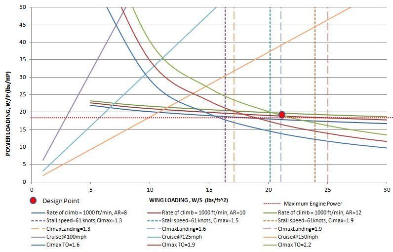
The design point is obtained from the performance sizing graph. The aircraft is
sized according to the FAR 23 requirements.
Figure 9. Performance Sizing Graph.
156.3 SUMMARY OF PERFORMANCE SIZING
The design point chosen is shown on the performance sizing graph. Table 12
provides the summary of performance sizing.
Table 12. Summary of Performance Sizing.
Stall Speed 61 Knots
Rate of Climb 1000 ft/min
Cl, max TO 2.2
Cl, max L 1.6
Aspect Ratio 10
Takeoff Wing Loading 21 lb / ft2
Takeoff Power Loading 19 lb / hp
Wing Span 43 ft
Chord 4.3 m
Engine Power 203 hp
166.4 BATTERY SIZING
The battery is sized following the method in reference [14]. The thrust power
generated by the propeller is:
(3)
For level, unaccelerated flight, thrust equals drag. Hence,
(4)
The energy needed from the battery is:
(5)
where,
E = Endurance of flight
EB = Battery Energy
PB = Battery Power
The specific energy (KWh) is found out using the above conversion method.
The mass of the battery is estimated using the specific energy of Li-Po battery. Tables
13 and 14 show the thrust power, specific energy and battery mass battery required
for different L/D ratios and cruise velocities. The endurance changes as a function of
cruise speed. A 30-minute reserve has been taken into account. The mass of the
battery is calculated based on the theoretical specific energy of the battery.
17Table 13. Effect of L/D over Thrust Power and Battery Energy.
Thrust Power(KW) Battery Energy(MJ)
L/D
V=150Km/h V=200Km/h V=250Km/h V=150 Km/h V=200Km/h V=250Km/h
13 73 96.9 121.2 1525.6 1570.1 1613.7
14 67.5 90 112.5 1416.7 1458 1498.5
15 63 84 105 1322.2 1360.8 1398.6
16 59 78.7 98.4 1239.6 1275.7 1311.1
17 55.6 74.1 92.6 1166.7 1200.7 1234.1
18 52.5 70 87.5 1101.8 1134 1165.5
19 49.7 66.3 82.8 1043.8 1074.3 1104.1
20 47.3 63 78.7 991.6 1020.6 1048.9
21 45 60 75 944.4 972 999
22 42.9 57.3 71.6 901.5 927.8 953.5
23 41.1 54.8 68.5 862.3 887.4 912.1
24 39.4 52.5 65.6 826.4 850.5 874.1
25 37.8 50.4 63 793.3 816.4 839.1
18Table 14. Effect of L/D over Specific Energy and Battery Mass.
Specific Energy(KW-hr) Battery Mass (Kg)
L/D
V=150Km/h V=200Km/h V=250Km/h V=150 Km/h V=200Km/h V=250Km/h
13 423.7 436.1 448.2 576.5 593.4 609.8
14 393.5 405 416.2 535.4 551.1 566.3
15 367.2 378 388.5 499.7 514.3 528.5
16 344.3 354.3 364.2 468.4 482.1 495.5
17 324.1 333.5 342.7 440.9 453.7 466.3
18 306.1 315 323.7 416.4 428.5 440.4
19 289.9 298.4 306.7 394.5 406.1 417.3
20 275.4 283.5 291.3 374.7 385.7 396.4
21 262.3 270 277.5 356.9 367.3 377.5
22 250.4 257.7 264.8 340.7 350.6 360.4
23 239.5 246.5 253.3 325.9 335.4 344.7
24 229.5 236.2 242.8 312.3 321.4 330.5
25 220.3 226.8 233.1 299.8 308.5 317.1
It is clear from Table 14 that a L/D ratio of 16 or above is required at a cruise
velocity of 200 km/h to achieve a battery mass of no more than 500 kg, as estimated
in the preliminary weight sizing earlier.
197.0 PRELIMINARY DESIGN
7.1 FUSELAGE LAYOUT
The fuselage is sized to provide adequate space for four passengers and their
baggage. The method in reference [10] is used to decide on the values of the various
fuselage parameters.
Figure 10. Fuselage Dimensions.
Fuselage Diameter = 4.5 ft
Fuselage Length = 27 ft
Tail Cone Length = 13.5 ft
Cabin Dimensions:
Maximum Height = 4.5 ft
Maximum Width = 5.5 ft
Maximum Length = 9 ft
207.2 ENGINE SELECTION AND DISPOSITION
To provide a clean flow over the wings, a fuselage-mounted single engine is
chosen. An electric motor with an output power of 160 KW and a 3-blade propeller
with a diameter of 5.2 ft are selected. The engine location is shown in Figure 11.
Figure 11. Nose Mounted Engine.
7.3 WING DESIGN
A cantilever, low wing is selected for the design due to its favourable ground
effect during takeoff and the shorter landing gear, which helps in reducing the
structural weight. Also, the wings can be used as a step to enter into the aircraft.
From the summary of the performance sizing results, the wing specifications can be
calculated:
Wing Area, S = 184 ft2
Aspect Ratio, AR = 10
Wing Span, b = 43 ft
21Chord, c = 4.3 ft
From the existing data of similar aircraft using [10], the other wing parameters
such as taper ratio, dihedral angle, sweep angle, twist angle, and incidence angle are
also obtained.
Taper ratio = 0.4
Dihedral = 7°
Sweep = 0°
Wing twist = -3°
Incidence angle = 2°
From reference [13],
(6)
where,
= mean aerodynamic chord = 4.3 ft
λ = taper ratio = 0.4
cr = root chord = 5.78 ft
ct = tip chord = 2.31 ft
To find the flap dimensions, the following approximation is used:
cf / c = 0.2
bf / b = 0.7
22Hence, the flap dimensions are:
cf = 0.86 ft
bf = 30 ft
Figure 12. Wing specifications.
7.4 WEIGHT AND BALANCE ANALYSIS
The various components that contribute to the aircraft weight are shown in
Figure 13 for the purpose of estimating the aircraft cg. Table 15 shows an estimation
of the empty weight cg at 10 ft from the nose of the fuselage using data from existing
aircraft [10], while Table 16 gives the location of the aircraft cg.
23Table 15. Estimation of Empty Weight CG.
Component Weight (kg) X (m)
Wings 265 2.56
Empennage 65 7.62
Fuselage 250 2.46
Nose Landing Gear 20 1.83
Main Landing Gear 100 2.54
Figure 13. Location of Various Components for Estimating the CG Location.
24Table 16. CG Estimation.
Component Weight (kg) x (m)
Propulsor Unit 100 0.15
Battery 350 1.06
Passengers 300 2.89
Empty Weight 750 3.04
Baggage 100 4.72
Battery 150 4.72
Figure 14. CG Excursion Diagram.
From Figure 14, the cg travel of the aircraft is 16 in or 31% of the wing mean
aerodynamic chord.
257.5 LANDING GEAR
A retractable, conventional, tricycle landing gear is chosen to reduce drag and to
provide the greatest extent of laminar flow over the wing during cruise. The landing
gear specifications and location are determined by the ground clearance and tip over
criteria [10]. To provide adequate clearance for the propeller, the length of the nose
landing gear is chosen at 4 ft and the length of the main landing gear at 3 ft.
The nose gear is placed 86 inches from the nose of the fuselage, while the main
gear is located 125 inches of the fuselage section. The static load per strut for the
nose and main landing gears is found from:
(7)
From equation (7) and typical landing gear wheel data [10], the landing gear
specifications are easily obtained.
7.6 EMPENNAGE
A T–tail is chosen for the proposed design because it provides the best location
for staying out of the wing wake and it increases the efficiency of the horizontal
stabilizer, thus requiring a smaller area. From the configuration layout, the distance
of the horizontal and the vertical stabilizer from the cg is obtained:
xh = 15 ft,
xv = 14.5 ft
26Hence
Sh = 32.2 ft2, Sv = 20.2 ft2
bh = 12.7 ft, bv = 30.3 ft
ch = 2.54 ft; cv = 3.7 ft
A taper ratio of 0.5 is chosen on both the horizontal and the vertical stabilizers based
on data from similar aircraft [10].
7.7 HIGH LIFT DEVICES
A plain flap is the most simple high lift device which provides a maximum
increment of 0.9 while adding less structural weight. Hence a plain flap is chosen in
this design. Table 17 gives the increment in lift coefficient for each device [13].
Table 17. Lift Coefficient Increments for Various Types of High Lift Devices.
High Lift Device ΔCl
Plain Flap 0.7-0.9
Split Flap 0.7-0.9
Fowler Flap 1-1.3
Slotted Flap 1.3 Cf/C
Double Slotted Flap 1.6 Cf/C
Triple Slotted Flap 1.9 Cf/C
Leading Edge Flap 0.2-0.3
27Leading Edge Slat 0.3-0.4
Kruger Flap 0.3-0.4
7.8 AIRFOIL SELECTION
The ideal and maximum lift coefficients for the airfoil are calculated from the
equations in reference [13]:
Clideal = 0.8
Clmax = 1.4
The airfoil is chosen primarily based on these two criteria. The ideal lift
coefficient is higher when compared to the average ideal lift coefficient, which is
usually in the range of 0.2 – 0.4. Hence, the induced drag produced by the wing will
be higher, but the Pipistrel Panthera has an ideal lift coefficient of 0.7, which is
comparable. The airfoils that have the highest ideal lift coefficient are considered to
find the best suitable one.
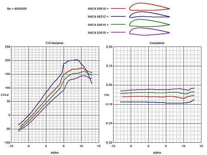
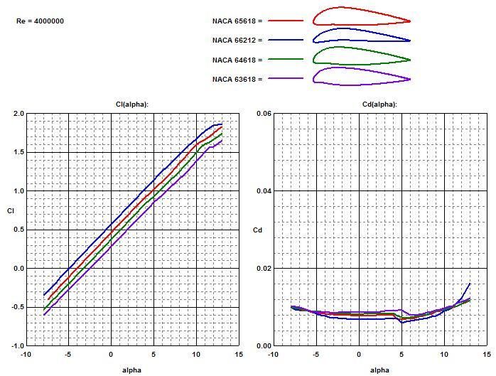
The NACA 6-series airfoils have high ideal lift coefficient [13]. A number of
airfoils were selected and their lift, drag, and pitching moment characteristics are
compared in Figures 15 through 20, to find the best airfoil. From the results, two
airfoils, NACA 65618 and NACA 66212 were selected and compared. The NACA
65618 generated high lift-to-drag ratios during cruise and a smaller pitching moment
coefficient, hence it is chosen for the proposed design.
28Figure 15. Drag Polar Comparison of Various Naca 6-Series Airfoils.
Figure 16. Lift and Drag Characteristics Comparison of Various Naca 6-Series Airfoils.
29Figure 17. Lift-To-Drag Ratio and Pitching Moment Comparison of Various Naca 6-Series
Airfoils
Figure 18. Comparison of the Drag Polars for the Naca 66212 and Naca 65618 Airfoils.
30Figure 19. Comparison of the Lift and Drag of the Naca 66212 and Naca 65618 Airfoils.
Figure 20. Comparison of the L/D Ratio and Moment of the Naca 66212 and Naca 65618
Airfoils.
317.9 DRAG POLAR
The preliminary estimates of the airplane low-speed drag coefficient and
Oswald efficiency factor are estimated for different configurations of the aircraft and
shown in Table 18 [10].
Table 18. Preliminary Estimates of C do and e.
Configuration E
Clean 0 0.80-0.85
Takeoff Flaps 0.010-0.020 0.75-0.80
Landing Flaps 0.055-0.075 0.70-0.75
Landing gear 0.015-0.025 No effect
The wetted surface area of the aircraft is estimated to be = 676 ft2 , while the
equivalent parasite area is estimated at f = 4. Hence:
(8)
(9)
32Table 19. Drag Coefficient and L/D Ratio for Different Aircraft Configurations.
Configuration L/D
Clean 0.044 0.8 18
Take off, gear up 0.22 2.2 10
Takeoff, gear down 0.24 2.2 9
Landing, gear up 0.18 1.6 8.7
Landing, gear down 0.19 1.6 8
This value for (L/D)max obtained from the drag polar satisfies the initial estimate of
the battery mass, as shown earlier in Table 14, hence, no iteration is needed.
3310.0 PRELIMINARY DESIGN LAYOUT
Figure 21 shows the preliminary design layout of the proposed 4-seat, general
aviation, electric aircraft.
Figure 21. Preliminary Design Layout.
Figure 22 shows the three views of the proposed electric aircraft.
Figure 22. Electric Aircraft: Three View.
3411.0 CONCLUSION
It is noted that the range and efficiency of the electric aircraft depend heavily on
the takeoff weight. The takeoff weight of 1,750 kg is much higher when compared to
aircraft of the same category such as, for example, the Pipistrel Panthera, which has a
takeoff weight of 1,200 kg. This, of course, is due to the higher L/D ratio, which
reduces the energy needed during flight, and as a consequence, the required battery
weight. Needless to say, the proposed design extrapolates on advances in battery
technology, composite structures, and aerodynamics to help achieve the performance
shown in this thesis. The next step is a detailed analysis of each subsystem to confirm
the feasibility of the proposed concept.
35REFERENCES
[1] Epstein, Aircraft propulsion, presented at NASA ARC green aviation workshop,
Mountain View, April 2009.
[2] G.L. Dillingham, Aviation and the Environment, United States Government
Accountability Office, 2008.
[3] CAFE: Electric aircraft symposium report, 2010. Retrieved from
[4] Aero-tv: Bye energy’s ele tri 172 - building a greener future for aviation, 2011.
Viewed at http://www.youtube.com/watch?v=Yjq8ixM0oEw
[5] D. Yoney, Cessna Developing Electric-Powered 172 Skyhawk, 2010. Retrieved
from
[6] J. Croft, Electric Propulsion is Gaining Horsepower with Experimental and Light
Aircraft Communities, Aug. 02, 2010. Retrieved from
[7] R. Coppinger, The Future is Electric for General Aviation, Apr 06, 2010.
Retrieved from
[8] Electric Aircraft, Mar. 09, 2012. Retrieved from
http://en.wikipedia.org/wiki/Electric_aircraft
[9] Antares H2/H3 Technical Data. Retrieved from http://www.lange-
aviation.com/htm/english/products/antares_h3/technical_data.html
[10] J. Roskam, Airplane Design vol I - Preliminary Sizing of Airplanes, 1985.
[11] K. Loftin, Subsonic Aircraft: Evolution and the Matching of Size to
Performance. NASA Reference Publication 1060.
[12] M. Sadraey, Aircraft Design: A Systems Engineering Approach. Wiley, 2012.
[13] E. Stephen, E. James, E. A Cost Comparison of Fuel-Cell and Battery Electric
Vehicles.
[14] J. Gundlach, Designing unmanned aircraft systems, 2012. Retrieved from
36[15] Wong, G. (2011, March 03). Elektra one: the electricity-powered plane.
Retrieved from http://www.ubergizmo.com/2011/03/elektra-one/
[16] Hanlon, M. (2009, June 22). Retrieved from http://www.gizmag.com/yuneec-
e430-electric-aircraft/12036/
[17] 4-engine electric cri-cri unveiled by eads. (n.d.). Retrieved from
http://www.eaa.org/news/2010/2010-06-24_cri-cri.asp
[18] (2011, Feb 26). Retrieved from http://www.technologicvehicles.com/en/green-
transportation-news/569/video-the-electric-self-launching-glider-pipi
[19] (2012, Apr 19). Retrieved from http://www.ecofriend.com/pipistrel-panthera-
ultra-sleek-aircraft-electric-hybrid-cousins-down-line.html
37You can also read