Failure modes of a vehicle component designed for fuel efficiency
←
→
Page content transcription
If your browser does not render page correctly, please read the page content below
Proceedings of the 2014 International Conference on Mathematical Methods, Mathematical Models and Simulation in Science and Engineering

        Failure modes of a vehicle component designed
                      for fuel efficiency
                                               M.R. Idris, W.M.Wan Muhamad, S.Z. Ismail

Abstract— Many automotive companies today are striving to build
a fuel efficient vehicle due to increasing demand of small compact
cars for urban use, high fuel prices and legislative requirements on
emission control. This research is part of a concept car project that
focuses on a weight reduction program. The component that is
subjected to weight loss is known as steering knuckle. This research
is to analyze the potential failure modes on a redesigned knuckle that
have achieved maximum limit for weight reduction. The original
component is then transformed into Finite Element Model (FEM)
using HyperWorks software. The weight topologies are tested under
different fatigue stresses for identification of crack initiation. A shape
optimization method was then employed to verify the potential
failures. The results will be presented in comparison to original
knuckle design. A recommendation to enhance the component                           EUROPMENT will do the final formatting of your paper.
strength will be proposed during the designing stage of the fuel                                  Figure 1: Steering Knuckle LH & RH
efficient car.

  Keywords—Knuckle,           Weight     reduction,    Finite   elements,
HyperWorks, Fatigue

                             I. INTRODUCTION
   In search to find replacement to fossil fuel, automotive
manufacturers developed various technologies such as electric
vehicle (EV), natural gas vehicle (NGV), biodiesel, hybrid etc.
However, during commercialisation, problems pertaining to
testing, costs and resources have yet to be resolved. A much
radical solution is neede in order to improve fuel efficency.
   The weight reduction of vehicle components is also a key to                                     Figure 2: Steering knuckle assembly
fuel efficiency. Lighter material weights will result in fuel
savings. Today, many vehicles are designed with lighter
parts/materials in order to reduce its total weight . A simple                         This research is to study the failure modes of components
weight test by author has revealed that by eliminating 20 kg                        that are subjected to weight reduction, in term of shape and
(spare tyre), the extra mileage gain is 8-10 km for every                           dimension. The selected part is a steering knuckle. This is a
100km. The test is conducted in the motorway without heavy                          safety part which is linked to brake disc and steering linkages.
traffic. The situation is likely to be doubled for city driving.                    Figure. 1 shows a set steering knuckles that are normally used
   The weight reduction activities on safety parts often seen as                    on cars and each part is weighing 1.5 kg.
major obstacle to the designers. Any small changes in                                  The steering knuckle is assembled on the brake disc housing
parameters of parts will affect the material stresses than can                      as illustrated in Figure. 2. The research explores the design
cause fatigue or crack initiation.                                                  optimisation using Finite Element Method to evaluate the
                                                                                    stress valus under loading constraints. The failure modes of
                                                                                    parts will be analysed. Key parameters will be determined to
                                                                                    further optimised the dimension (weight lost) and hence to
   This work was supported is sponsored by Ministry of Science, Technology          reduce potential failures.
and Innovation (MOSTI) Malaysia
   M. R Idris is with Universiti Kuala Lumpur, Institute of Product Design
                                                                                       Many think that EVs are bigger and heavier than
and Manufacturing (IPROM), Malaysia (Telephone: 60391795000; fax:                   conventional ones because of their use of large batteries. This
60391795001, email: mrazif@iprom.unikl.edu.my)                                      might be true for long range vehicles that require big heavy
   W.M.W.Muhamad is with Universiti Kuala Lumpur, Malaysia France                   batteries. The battery is usually considered the main
Institute(MFI), Malaysia, email: drwmansor@mfi.unikl.edu.my)
                                                                                    component in the EV weight. So, it is important to examine the
   S.Z. Ismail is with Universiti Kuala Lumpur, Institute of Product Design
and Manufacturing (IPROM), Malaysia (email: s.zubaidah@unikl.edu.my)                battery weight in the urban EV model. EV will use a Lithium-
                                                                                    ion battery with average specific energy 0.13 kWh/Kg. For a

       ISBN: 978-1-61804-219-4                                                103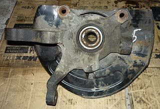
Proceedings of the 2014 International Conference on Mathematical Methods, Mathematical Models and Simulation in Science and Engineering

60-mile - 0.2 kWh/mile (97-mile - 0.12 kWh/km) urban                     stiffness-to-mass ratio by applying CAE based optimization
vehicle, the total needed battery capacity would be 12 kWh.              tools within consistent problem formulations. Since structural
Therefore, the expected battery weight is about 90 kg which is           optimizations have not been widely applied to the design of
quite satisfactory for an urban EV. Moreover, the electric               heavy vehicle structures such as a flatbed trailer, substantial
motor of an EV is much lighter than the internal combustion              improvement in structural performances can be expected by
engine of a conventional vehicle delivering the same power. In           using a systematic optimization procedure. [5]
addition to the fact that the EV does not need manual or                    Optimization methods were developed to have lighter, less
automatic gearbox, it is also possible to eliminate every                cost and may have better strength too. Many optimization
mechanical transmission using wheel-drive motors.                        types, methods and tools are available nowadays due to the
Furthermore, future advancements in battery technology will              revolution of the high speed computing and software
make batteries smaller and lighter which will in turn lead to            development. There are four disciplines in structural
further reductions in weight and size of the EV. [1].                    optimization process [6,7,8].
Biodiesel-fuelled diesel engines offer a substantial opportunity            Topology optimization: provides optimum material layout
to address two major issues facing our global society: energy            according to certain the design space and loading case.
consumption and global warming. A substantial portion of                    Shape optimization: supports optimum fillets and the
energy consumption and carbon dioxide emission rates are                 optimum outer dimensions.
furnished by the transportation industry, which in the United                 Size optimization: to obtain the optimum thickness of a
States, for example, represented nearly 30% of the energy flow           component.
and over 31% of the vented CO2.[2]. However, the resources                    Topography: an advanced form of shape optimization, as
for biodiesel are limited.                                               it will generate reinforcements such as beads.
   The powertrain of a parallel hybrid electric vehicle (PHEV)              Shape optimization refers to the optimal design of the shape
is a hybrid system of an engine and an electric drive system.            boundary of structural components, which is becoming
Under the control of the advanced vehicle controller unit                increasingly important in mechanical engineering design.
(VCU), the drive force requested by the driver is optimally              Current interest in structural shape optimization is largely
distributed between the engine and the motor. The optimal                motivated by demands for more cost competitive design
distribution of the drive force is supervised by the vehicle             throughout the industrial sector. Therefore, considerable effort
energy management strategy (EMS), which is the kernel part               has been devoted to developing efficient techniques for shape
of the real-time control algorithm of the PHEV, and it is one of         optimization [6]. Shape optimization is expected to further
the key PHEV technologies in which many researchers are                  improve a design in achieving certain objectives after topology
engaged. The goal of the EMS is to achieve a high efficiency,            optimization was performed, such as in this work.
energy saving, and low emissions vehicle by controlling the                 Finite element method used for many type of analysis, such
hybrid powertrain system coordinately. This means that the               as linear analysis, nonlinear analysis, fatigue analysis and
performance of a PHEV is strongly dependent upon the                     another types. FE analysis was developed to solve the
control of the hybrid powertrain system, which includes the              optimization process such as Optistruct linear solver [8],
engine, electric motor, electrical energy system, automatic              TopShape [9], ANSYS, NASTRAN [10], ABAQUS etc.
clutch and transmission.[3]
   Stress-life fatigue analysis was conducted to correlate the
crack location between the failed component and the                                      II. RESEARCH AIM AND OBJECTIVE
simulation model. A new design proposal was determined with                 This research aims to provide solution to a car designer in
the topology optimization approach, and then design                      optimizing the component structure against the types of failure
optimization by response surface methodology was effectively             modes. Designing a light weight component for fuel efficiency
used to improve the new clutch fork design. The topology                 is likely to increase the fatigue stress distribution.
optimization approach used in this study has found an original              This study will identify the potential failure modes of crack
load balanced optimum material distribution and it is                    initiation using topology and shape optimization approach.
important to know the design space, the boundary conditions
and the loads throughout the process. With the results from the
topology optimization, design engineer are capable to define a                                  III. METHODOLOGY
detailed design. Topology optimization has proven very
effective in determining the topology of initial design                    Topology and Shape optimization was applied to reduce
structures for component development in the conceptual                   volume or weight of rear knuckle component in a local car
design phase. After determining the initial topology, shape              model. The approach is shown in Figure 3.
optimization can be used for the final design. [4]                         Modeling, simulation and optimization processes used
   High stiffness, high strength, and light weight are important         software modules included in Altair's HyperWorks. Utilizing
issues when designing vehicle structures. To achieve such                HyperMesh, solid model was imported for finite element
goals, the recent applications of CAE based structural                   modeling where loads and constraints were applied.
optimizations to the design of lightweight vehicle parts with              Shape optimization process requires shape definition for
high static and dynamic performances are regarded as efficient           design variables and HyperMorph was used to conduct such
approaches. Flatbed trailer is optimized to have a high                  purpose. Then, shape optimization process was conducted

      ISBN: 978-1-61804-219-4                                      104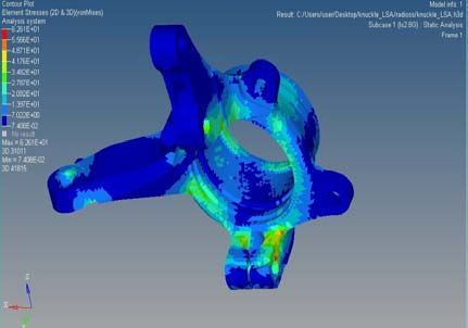
Proceedings of the 2014 International Conference on Mathematical Methods, Mathematical Models and Simulation in Science and Engineering
using OptiStruct. Furthermore, Hyperview and Hypergraph The applied material properties are presented in Table 1.
were used to display and plot the data for results interpretation.
Table 1: Material properties of knuckle
Material Steel
Density 7.85e-9 tonne/mm3
Poisson’s Ratio 0.3
Modulus of elasticity 200000 MPa
Yield Stress 478.32 MPa
Ultimate tensile stress 621 MPA
B. Boundary Conditions and Loading
In actual test performed in a local car manufacturing
company, the knuckle is mounted when it subjected to the
load. To represent this condition it is constrained from the
back with all degree of freedom constraints.
The part must be able to withstand 4000N sinusoidal load
and greater than 350000 cycles.
C. Optimization Parameters
The vector of nodal coordinates (x) is used to define the
shape of knuckles structure in finite element model.
Using the basis vector approach, the structural shape is
defined as a linear combination of basis vectors. The basis
vectors define nodal locations.
x = ∑ DVi . BVi (1)
Figure 3: Design optimization flowchart Where x is the vector of nodal coordinates, BVi is the basis
vector associated to the design variable DVi.
Shape definition is based on the possible design space that Using the perturbation vector approach, the structural shape
allows some of region in the component to be changed. It change is defined as a linear combination of perturbation
depends on the interface and connection condition between the vectors. The perturbation vectors define changes of nodal
component and other components that are attached to the locations with respect to the original finite element mesh.
component.
x = xo + ∑ DVi . PVi (2)
IV.MODEL AND NUMERICAL ANALYSIS Where x is the vector of nodal coordinates, xo is the vector
A. Finite Element Model of nodal coordinates of the initial design, PVi is the
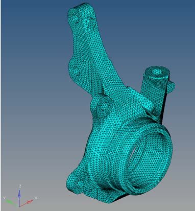
Finite element model for knuckle is shown in Figure 4 below. perturbation vector associated to the design variable DVi. This
approach is adopted by the OptiStruct software.
A general optimization or a mathematical programming
problem can be stated as follows [11].
(3)
which minimize f(X)
subject to the constraints
gj (X) ≤ 0, j = 1, 2, . . . ,m
lj (X) = 0, j = 1, 2, . . . , p
where X is an n-dimensional vector called the design vector, f
(X) is termed the objective function, and gj (X) and lj (X) are
known as inequality and equality constraints, respectively.
Figure 4: Finite element knuckle model
ISBN: 978-1-61804-219-4 105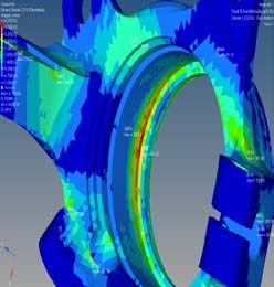
Proceedings of the 2014 International Conference on Mathematical Methods, Mathematical Models and Simulation in Science and Engineering
The objective of this optimization is to minimize volume
while maximum stress of the elements became constraint
variable. Design variables were determined using
Hypermorph.[12]
Seven shapes were defined (shape 1, shape 2, shape 3, shape
4, shape 5, shape 6 and shape 7) as design variables [9].
Figure 7: Element of Stress Region (for data collection)
V. RESULTS AND DISCUSSION
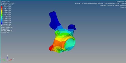
Figure 5: Knuckle analysis (Displacement Contour) Topology Optimization
The data for the element of stresses were gathered using the
Figure 5 shows the knuckle part that has been drawn in HyperWork Finite element method.
finite element using HyperWork software. The part was
analyzed under working loading constraints. The displacement Table 2: Stress values based on region
contour indicates one side of part has been subjected to major Region
ID Element Element of Stresses
displacement. Location
41416 22.056
R1
178977 21.659
R2 33550 25.115
169422 23.887
159392 22.411
R4 168987 15.639
100040 33.084
168819 14.36
R5 167159 22.815
185359 35.696
R7 31645 38.712
194183 49.016
R8 133817 38.126
173430 25.31
R9 168766 28.81
158717 35.166
The data in Table 2 indicated that R7 (38.712, 49.016) &
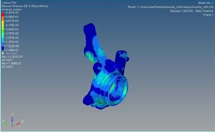
Figure 6. Knuckle analysis (Element of Stresses) R8 (38.126) are subjected to higher stress area. However,
based on the red zone stress topology (Figure 8 & 9), the stress
Figure 6 illustrates the state of element stress when part is concentrations were appeared at the mounting holes. This
subjected under loading constraints. The red zones indicate means that under fatigue load condition, both R7 and R8 are
the concentration of stress area where a potential failure (weak likely to fail due to crack initiation.
point) tends to occur. The failures can be in the form of crack
initiation or chip. Meanwhile the green colour zones are
subjected to fatigue stress as they have continuous
displacement at the same points over time. In this research,
the stresses are analysed in 9 regions as shown in Figure 7.
ISBN: 978-1-61804-219-4 106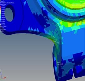
Proceedings of the 2014 International Conference on Mathematical Methods, Mathematical Models and Simulation in Science and Engineering

                                                                        moved to different regions with more severe red zone areas as
                                                                        shown in Fig. 10 and Fig. 11.
                                                                                                     VI. CONCLUSIONS
                                                                           Designing a fuel efficient car needs a systematic approach
                                                                        without compromise the safety and quality. Many
                                                                        developments toward new technologies (EV, NGV and hybrid)
                                                                        for fuel efficient and zero emission are taking place. However,
         Figure 8: R7                     Figure 9: R8                  the fundamental problems pertaining to batteries life, material
                                                                        costs and other design constraints are yet to be resolved. This
Shape Optimization                                                      research has successfully explored the topology and shape
                                                                        optimization methodologies to reduce component weight and
   Shape definition is based on the possible design space that          as well as predicting the potential failure modes. This method
allows some of region in the component to be changed. It                is found to be useful and reliable during parts development
depends on the interface and connection condition between the           stage.
component and other components that are attached to the
component.                                                                                 ACKNOWLEDGEMENTS
                                                                            This research was sponsored by Ministry of Science,
                                                                        Technology and Innovation (MOSTI) Malaysia TechnoFund
            Table 3: Stress values based on region                      Grant. The authors would like to thank PROTON and UniKL
 Region                                                                 for their support.
                  ID Element         Element of Stresses
 Location
                                                                                                    REFERENCES
 R2               170215             265.287
                                                                        [1]  Noha Sadek. Urban electric vehicles: a contemporary business case.
                  163864             197.686                                 Eur. Transp. Res. Rev. (2012) 4:27–37. 2012
                                                                        [2] B.T. Tompkins, H. Song, J.A. Bittle, T.J. Jacobs. Efficiency
 R3               158999             404.124                                 considerations for the use of blended biofuel in diesel engines. Applied
                  169876             298.43                                  Energy 98 (2012) 209–218. 2012
                                                                        [3] B. Suh, A. Frank, Y. J. Chung, E. Y. Lee,Y. H. Chang, S. B. Han.
                  164975             243.128                                 Power train System Optimization for a Heavy-duty Hybrid Electric Bus.
                  100040             216.217                                 International Journal of Automotive Technology, Vol. 12, No. 1, pp.
 R5               53344              148.259                                 131−139 (2011). 2009
 R6               133446             191.321                            [4] Necmettin Kaya, Idris Karen, Ferruh Ozturk. Materials and Design 31.
                                                                             Re-design of a Failed Clutch Fork Using Topology and Shape
 R7               59754              192.57                                  Optimization by the Response Surface Method. Materials and Design
                  185361             247.053                                 Volume 31, Issue 6, June 2010, Pages 3008-3014. 2010
                  39479              281.388                            [5] Gang-Won Jang, Min-Su Yoon, Jae Ha Park. Lightweight flatbed trailer
                                                                             design by using topology and thickness optimization. Struct Multidisc
                  160985             353.481                                 Optim (2010) 41:295–307. 2009
 R8               103931             187.934                            [6] Altair Hyperworks 10, Altair Engineering Inc., India, 2010.
                                                                        [7] Kojima,Y., “Mechanical CAE in automotive design”, R & D review of
                                                                             Toyota CRLD, Vol 35, No. 4, 2000.
                                                                        [8] Obayashi S, Tsukahara T. “Comparison of optimization algorithms for
                                                                             aerodynamic shape design”. AIAA Journal, Vol. 35, No. 8. 1997.
                                                                        [9] Richards RA. “Zeroth-order shape optimization utilizing a learning
                                                                             classifier system”. PhD Dissertation, Mechanical Engineering
                                                                             Department, Stanford University, 1995.
                                                                        [10] Yang. R.J., “Design Modeling consideration in Shape Optimization of
                                                                             Solids”, Computers & Structures, Vol. 34, Issue 5, 1990
                                                                        [11] Rao S.S., “Engineering Optimization Theory and Practice”, John Wiley
                                                                             & Sons, Inc4th edition, 2009.
                                                                        [12] HyperMorph Introduction Methods for Morphing Finite Element
                                                                             Models, Altair Engineering Inc., India, 2006.

        Figure 10: R3                     Figure 11: R8

  In this research the` weight lost’ parameters are defined as
to reduce the shape size and its dimensions. For
experimentation purposes, the part is subjected to 10 %
REDUCTION in thickness, diameters and angles. The part is
now redesigned and was tested under the same loading
constraints. The results show some stress concentrations have

      ISBN: 978-1-61804-219-4                                     107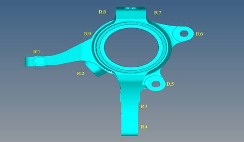
You can also read