Burst Testing Ethernet Networks - Application Note - VIAVI Solutions
←
→
Page content transcription
If your browser does not render page correctly, please read the page content below
VIAVI Solutions
Application Note

Burst Testing
Ethernet Networks
Customer traffic is typically bursty. Unfortunately,
traditional Ethernet testing was designed that variance.

Emerging high-speed protocols in mobility and access networks combined with
quality-of-service demands from business customers for services such as cloud
computing, place increased performance demands on metro Ethernet networks. Specifically,
these networks need to tolerate increasingly bursty transmission control protocol (TCP) traffic
while maintaining high performance for real-time applications like voice and video.

In the past, verifying Ethernet network key performance     An integrated approach to burst testing will uncover the
indicators (KPI) such as throughput, frame loss, latency,   misconfiguration of policing settings and inadequate
and packet jitter has been sufficient to validate           buffer sizes that are common problems at demarcation
network configuration and performance. Presently,           points on the network edge. It will also uncover
and especially with the emergence of LTE/4G and             incorrect buffer sizes at aggregation points deeper in
virtualized computing, using only these metrics will not    the network. This application note will describe how
provide enough test coverage to ensure a high-quality       TCP creates bursty traffic, how Ethernet networks
customer experience in the presence of bursty traffic.      accommodate these data bursts, and how an integrated
Best practices for Ethernet service activation need to      burst test methodology with simple pass/fail results
include tests to verify explicitly network configuration    can expose and help fix the problems that lead to a bad
and robustness in the presence of bursty traffic both at    customer experience.
the Ethernet level and at the transmission-convergence
(TC) layer.
                                                             Traffic in real networks is bursty due to the nature of
                                                             TCP (75 percent of all Internet traffic).
An integrated burst-testing methodology offers
                                                             New mobility standards and cloud-computing
carriers a solution for guaranteeing network
                                                             applications make problems with traffic bursts even
configuration and performance in both mobility               more detrimental to the user experience.
backhaul and business-services applications. Because
                                                             Traditional assurance standards (RFC 2544 and Y.1564)
poor performance can occur due to a wide variety             have overlooked burst testing or label it as an option.
of potential misconfigurations of different kinds of
                                                             Testing with only constant bit-rate traffic does not
network equipment, optimal service-activation test           validate buffer and policer configuration.
methodologies will include tests to expose problems at
both the Ethernet and TCP layers of the network.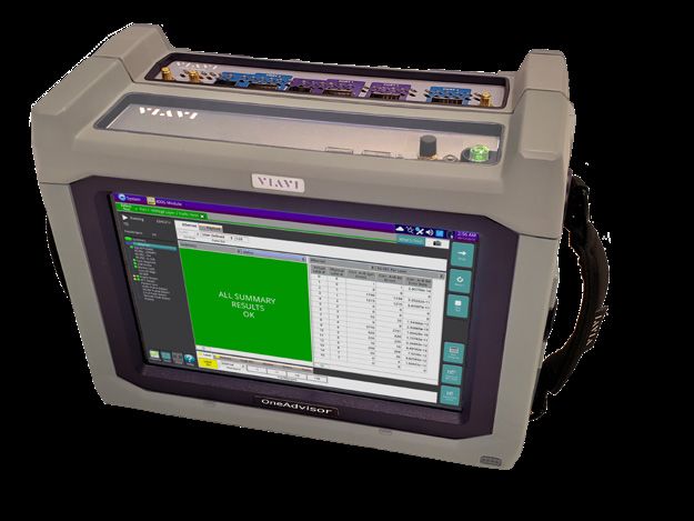
Why Test Burst
                                                                                               VIAVI offers a truly integrated
Traditional Ethernet service-activation test methodologies such as RFC 2544
                                                                                               approach to burst testing.
focus on testing with constant bit rate traffic. Constant bit rate testing
                                                                                               Committed burst size tests to
is an important step in testing Ethernet services because it can measure
                                                                                               identify misconfigurations in
throughput, frame loss, latency, and packet jitter while the network is                        policing and buffer sizes.
operating in steady state for a given rate of test traffic. While testing with
                                                                                               TCP TrueSpeed™ tests to validate
constant bit-rate traffic can validate important KPIs, it does not validate                    service performance and eliminate
how well the network will perform when transporting the expected traffic                       finger pointing.
patterns which will likely consist of a mix of constant bit-rate voice and video
traffic and bursty data traffic. Ensuring that this bursty data traffic can pass through the network without frame
loss and without impacting other services are the two goals of burst testing.

Wireless Backhaul
Wireless backhaul networks provide an interesting case study in the negative impacts of failing to test network
reliability to bursty traffic. Figure 1 shows a simplified view of a wireless backhaul network where a wireless
provider is contracting with a backhaul provider to transport their Ethernet traffic from a cell site to the
location of their mobile telephone switching office (MTSO). In this example, data packets using TCP/IP will be
sent from wireless devices to a base transceiver station (BTS) using a wireless protocol such as universal mobile
telecommunications system (UMTS) or                Wireless Provider                   Backhaul Provider            Wireless Provider

long term evolution (LTE). The packets
will then be transported to the wireless
                                                                                            Ethernet
provider’s MTSO over an Ethernet                                                            Backhaul                    BSC/RNC
network.                                         Cell Site

As Figure 1 illustrates, any Ethernet
                                                                              Dropped frames here
frames carrying TCP traffic that are           Cause retransmissions here
dropped in the Ethernet backhaul
                                                                            Figure 1. Mobility backhaul network
network will cause retransmissions
over the wireless protocol. This occurs because, as a reliable protocol, TCP will retransmit datagrams that do not
successfully traverse the network to ensure that all of the data requested will eventually arrive. In mobile networks,
this causes additional stress on wireless spectrum, which can be the most congested part of the network. Wireless
retransmissions not only lead to lower data throughput for individual users, but also degrades performance for all
customers using the shared wireless spectrum.

One of the biggest advantages of fourth-generation wireless protocols like LTE is the ability to support increased
data-throughput rates. With higher throughput rates, data traffic becomes increasingly bursty because each
datagram transfer can occur at a higher max rate and in a shorter period of time. This effect is then compounded
by adding bursts from other users on the wireless network to create the traffic pattern that will be sent to the
Ethernet backhaul network. If the Ethernet switches and routers are not configured properly to accommodate these
bursts of traffic, the performance degradation will be even more noticeable to users who have become accustomed
to higher-rate data services on their mobile devices. To ensure optimal performance for their wireless customers
and reduce customer churn, mobile operators and their Ethernet backhaul partners should adopt a comprehensive
burst-testing methodology.

2 Burst Testing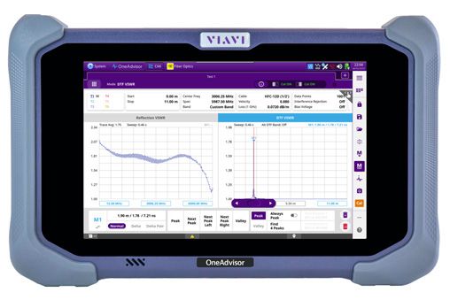
Cloud Computing
The emergence of cloud computing, with virtualized computing and storage resources accessible to business
customers via a metro Ethernet network interface, offers service providers massive new revenue opportunities.
However, it also presents new operational challenges. Figure 2 illustrates a simplified network diagram where
a business customer has two office locations connected to each other and to the public Internet via a service
provider’s metro Ethernet network. In addition, each office location has access to virtualized computing and storage
resources located at either a service provider or third-party data center. In this scenario, the customer might use the
cloud to provide additional computing capacity at peak times, increased service availability and reliability, or data
backup for disaster recovery. Regardless of the application, the data sent to and from the virtual computing and
storage resources will use TCP as the transport layer protocol, which will generate more bursty data traffic in the
network.

                            Virtualized cloud          TCP Retransmissions reduce
                         computing and storage        performance on mission-critical
                                                           business applications

                                                                                              Customer Location A

                                                                   Metro Ethernet
                                                                     Network                  Customer Location B
                                   www

                                                 Figure 2. Business services with the cloud

As illustrated in Figure 2, retransmissions in cloud-computing applications will slow data transfer speeds and reduce
performance for the business applications which are running in the virtual environment. To make matters even
worse, because the customer is charged based on usage, reduced application efficiency introduced by network
problems translates directly into a higher cost for the customer.

3 Burst Testing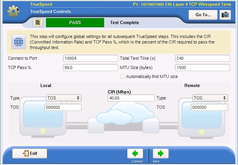
TCP Traffic — Bursty by Nature
As illustrated in Figure 3, common applications can be classified by the type of traffic that they produce—either
bursty traffic or constant bit rate traffic. Real-time applications such as voice and video tend to produce traffic
that has a constant bit rate because the audio or video signals that need to be transported across the network
are generally constant bit rate signals themselves. When transported across an IP network, real-time voice and
video traffic typically utilize user datagram protocol (UDP) because reduced latency is of great importance and the
application layer can account for some level of lost or out-of-order datagrams. Long delays and retransmissions
cause noticeable performance degradation for the user.

                                                  Bursty Traffic         Constant Traffic
                       7   Application
                                                  HTTP, FTP, E-mail,      Voice and Video
                       6   Presentation             Sharepoint,
                                                   Communicator,
                       5    Session              Facebook, YouTube

                       4   Transport                    TCP                      UDP

                       3    Network               Traffic                  Traffic

                       2   Datalink

                       1    Physical
                                                        Time                     Time

                                                 Figure 3. TCP vs. UDP

By contrast, applications that primarily transfer data, such as HTTP, FTP, and e-mail, require high reliability, meaning
that all segments transmitted across a network appear in order and without lost segments. These data-centric
applications rely on TCP because it was designed to provide these features. To provide reliable data transfer at the
highest speeds possible, TCP uses a variety of algorithms to maximize throughput while avoiding data loss. If a loss
is detected, TCP will retransmit the lost data segment, but also will potentially change the rate at which it sends
additional data. The result is a protocol that guarantees reliable transfer, but does so by creating burst traffic as
illustrated in Figure 3.

4 Burst Testing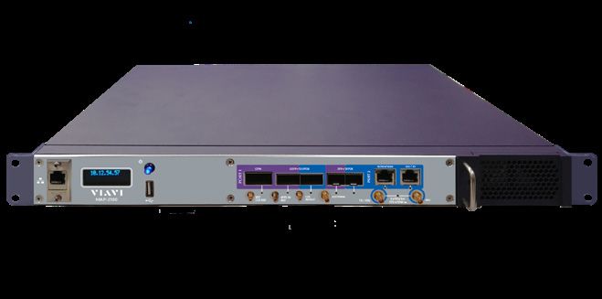
Bandwidth Profiles — Committed Information Rate (CIR) and Committed Burst Size (CBS)
Metro Ethernet networks employ sophisticated bandwidth profiles for each Ethernet virtual connection (EVC) so
that both the user and the service provider agree which traffic conforms to their service level agreement (SLA)
and which does not. To account for the bursty nature of data traffic, Ethernet bandwidth profiles define both a
CIR and a CBS among other attributes1. The CIR defines the average rate in bits-per-second of Ethernet service
frames that the network will accept and deliver while meeting agreed-
upon service performance objectives2. If all network traffic traversed at                                             It is important to note that TCP
                                                                                                                      will try to transmit bursts of data
constant bit rates, defining just a CIR would be sufficient to characterize                                           at the physical line rate and not at
the bandwidth profile. However, as illustrated in the previous section, data                                          the contracted CIR.
traffic transported via TCP tends to be bursty in nature. Along with a CIR, a
bandwidth profile must also include a CBS, which is the maximum number of bytes available for burst at any rate
up to and including the line rate while remaining CIR-conformant. For example, if the physical port is 1 Gbps, and
the CIR is 100 Mbps, TCP will burst at 1 Gbps. Ethernet network equipment should be tested with line rate bursts
because it should be able to handle a specific amount of burst in short time periods above the CIR.

Figure 4 illustrates a common implementation for bandwidth profile enforcement known as the token bucket
algorithm. This application note will focus on the “committed” or “C” bucket, which is used to determine CIR-
conformant service frames. Conceptually, the C bucket is initially filled with CBS “tokens” where each token can
be used to admit one byte of Ethernet service frame traffic into the network as CIR-conformant. When a new
service frame enters the network, the length of the service frame in bytes is checked against the number of tokens
remaining in the C bucket. If enough tokens are present, the service frame will be admitted to the network as CIR-
conformant and the number of tokens left in the bucket will decrease by the number of bytes in the service frame.
If there are not enough tokens present, the service frame is not CIR-conformant but may still be admitted to the
network depending on the excess information rate (EIR) and excess burst size (EBS) attributes of the bandwidth
profile. As illustrated in the diagram below, new tokens are added to the C bucket at a rate of CIR/8 times-per-
second. Conceptually, the CBS is the size of the bucket, the CIR is that rate at which the bucket is filled with tokens,
and the rate at which CIR-conformant service frames are admitted to the network (the token usage rate) is the
drain rate.                                                         “Green”Tokens
                                                                Refilled at committed
                                                                Information Rate (CIR)

                                                                                             “Yellow” Tokens
                                                                                             Refilled at Excess
                                                                                          Information Rate (EIR)

                         Service Frames Arrive at UNI
                                                                           Token Not Available

                                                Committed
                                            Burst Size (CBS)

                                                                                                     Token Not Available
                                                                                Excess
                                                                                 Burst
                                                    Token Available               Size
                                                                                 (EBS)

                                                                                                    Token Available

                                                                                                     Service Frames Admitted to Network

                                                               Figure 4. Token bucket algorithm

1. The other bandwidth profile attributes defined in MEF 10.2—EIR, EBS, coupling flag (CF), and color mode (CM)—are outside the scope of this
   application note.
2. Common performance objectives are maximum frame loss, latency, and packet jitter.

5 Burst Testing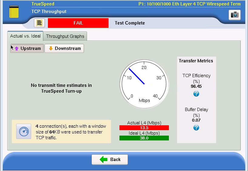
The following examples will further illustrate the significance of CIR and CBS for a service that has a UNI line rate
of 1 G, a CIR of 40 Mbps, and a CBS of 64 KB.

Example 1
A user sends a 64 KB burst of service frames at line rate, which takes approximately 0.512 ms3, then the user
stops transmitting for 12.3 ms before beginning another 64 KB burst. In this case, all of the service frames will be
marked as CIR-conformant and admitted to the network. Initially, the C bucket was filled with 64 KB of tokens.
As service frames arrived, 64 KB of tokens were depleted, but during the burst tokens were refilled at a rate of
5 MBps, leaving 2.56 KB at the end of the burst. During the subsequent idle period of 12.3 ms, the token bucket
would have refilled to the initial level of 64 KB. So, a user can send a 64 KB burst of service frames at any rate up
to and including the line rate every 12.8 ms and guarantee that every service frame will be CIR-conformant with a
significant margin.

                                                            Figure 5. Example 1

Example 2
A user sends a 135 KB burst of service frames at line rate, then stops transmitting for 25.92 ms before beginning
another 135 KB burst. In this case, approximately 69 KB4 of the service frames will be admitted to the network as
CIR-conformant while the rest of the service frames will be marked as not CIR-conformant and may or may not
be dropped depending on EIR and EBS settings. Initially the C bucket contained 64 KB of tokens, which began
to be depleted as the burst frames arrived. During the burst, which lasted 1.08 ms, the C bucket refilled with 5.4
KB of tokens. The 135 KB of burst frames is greater than the 69.4 KB of tokens available in the C bucket so some
frames will be marked as non-CIR-conformant. After being completely depleted during the burst, the C bucket
will completely refill during the idle period so that it will be able to accommodate approximately 69.45 KB of the
subsequent burst as CIR conformant with the remainder non-CIR-conformant.

                                                               Figure 6. Example 2

 3. (64 KB * 8 bit/B) / 1 G = 0.512 ms — for simplicity, calculations disregard Layer 1 overhead, which is approxi-
    mately accurate assuming large frame sizes
 4. 640B + (12.672 ms * 40 Mbps /8 bit/B) = 64 KB
 5. The exact amount will depend on frame size

6 Burst Testing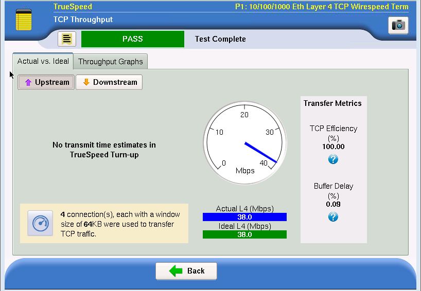
Testing Correct CBS Configuration
VIAVI Solutions has implemented a CBS test methodology in both SAMComplete™ Y.1546 and enhanced RFC 2544
automated service activation workflows. The following demonstrations will illustrate how these tests can be run
using two T-BERD/MTS-6000A test sets equipped with Multi Service Application Modules (MSAM) in a network
setup with a Cisco ME-3400 Metro Ethernet Switch and a delay element used to simulate a wide area network
(WAN) environment. As shown in Figure 7, the ME-3400 1 Gbps Ethernet interfaces will be configured for a 40 Mbps
CIR and a 64 KB CBS to match the configuration of the theoretical examples described above. The switch will be
configured to drop any received frames that are non-CIR-conformant.

                                         Policer:
                                     40 Mbps CIR
                                     64 KB CBS

                                 GigE                                 GigE       54 ms Delay   GigE
                                                    Metro Ethernet
                                                       Switch

                  T-BERD/MTS-6000A                  Cisco ME-3400                                T-BERD/MTS-6000A
                       Near End                                                                       Far End

                                                      Figure 7. Test network diagram

In this test setup, the T-BERD/MTS-6000A labeled Near End will initiate a CBS test while the T-BERD/MTS-6000A
labeled Far End will be automatically configured by the near-end device to loopback the test frames.

Using the test network described above, the following tests will illustrate CBS testing from two different
perspectives. The first test will show how a wireless operator who has contracted with an Ethernet backhaul
provider for backhaul service will ensure that 64 KB bursts of service frames will traverse the backhaul network
without any packet loss. The second test will show how an Ethernet service provider who has specific CIR and CBS
values specified for an Ethernet service can verify that the policing settings are, in fact, correctly configured. These
two tests will run as a part of the enhanced RFC 2544 test application. Note that a user can also run similar CBS
tests as part of the Y.1564 SAMComplete application, which would be desirable for network interfaces supporting
multiple classes of service.

7 Burst Testing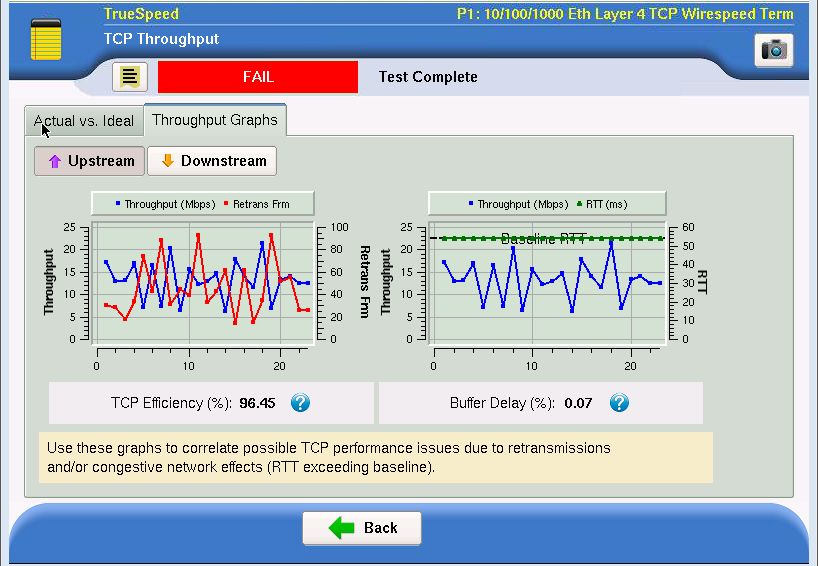
Test 1 — Testing with a 64 KB Burst
In the Enhanced RFC 2544 application, the Select Tests setup screen lets a user select which tests to run. The screen
in Figure 8 shows that the user wants to run throughput and burst tests.

                                                 Figure 8. Test 1 – Select Tests setup screen

The Utilization setup screen shown in Figure 9 lets a user configure both the bandwidth units and the maximum
bandwidth, which have been configured for 40 Mbps for Layer 2, conforming to the CIR.

                                           Figure 9. Test 1 – Utilization setup screen

8 Burst Testing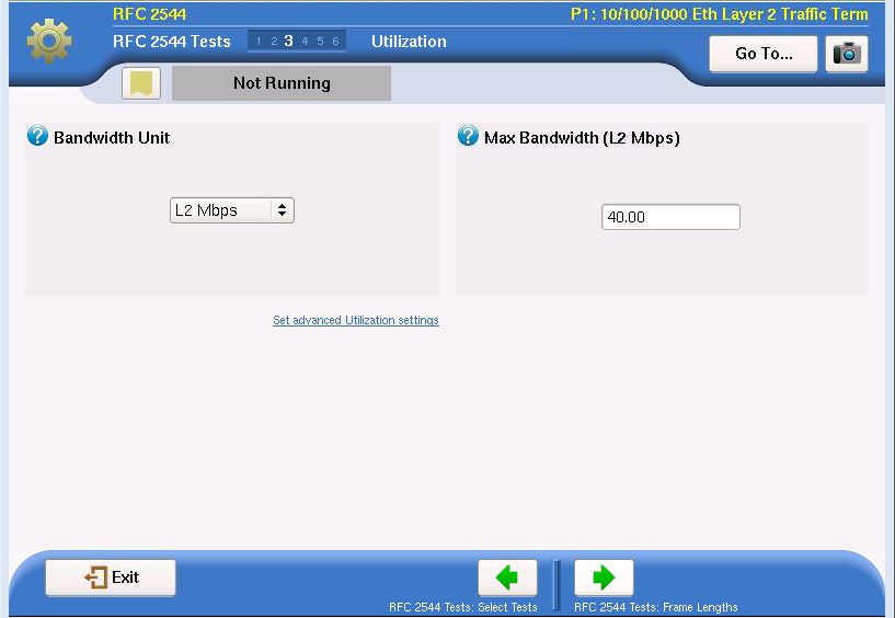
The Frame Lengths setup screen shown in Figure 10 lets a user configure each frame length to be used for both
Throughput and CBS tests. This screen shows that frame lengths of 64 to 1518 bytes have been selected.

                                         Figure 10. Test 1 – Frame Lengths setup screen

The Burst Test setup screen in Figure 11 lets a user configure both the burst test type to run as well as the CBS
value. This example shows that the Committed Burst Size test type has been selected and the CBS value is set to
64 KB.

                                            Figure 11. Test 1 – Burst Test setup screen

9 Burst Testing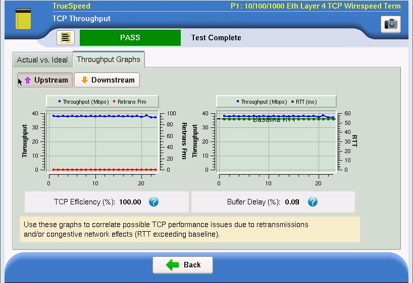
This test first checks network throughput using constant bit rate traffic at the specified CIR to validate proper
network configuration. Figure 12 shows that based on this configuration setup, the test measured throughput
for various frame lengths from 64 bytes to 1518 bytes and the test passed for all packet lengths, indicating that
it was correctly configured. Note that the Layer 2 throughput measured 40 Mbps for all frame lengths and that
the required Layer 1 throughput is higher for smaller frame lengths than for larger ones due to the fixed Ethernet
overhead size.

                                           Figure 12. Test 1 – Throughput Test results

The Burst Test results screen shown in Figure 13 displays the parameters used in the CBS test and the results for
each selected frame size. Note that the transmitted burst size for each frame length is exactly 64 KB for frame
lengths that divide evenly into 64 KB and is as close to 64 KB as possible for those that do not divide evenly into
64 KB. The average received burst size indicates the size of the bursts received from the network (with the far-
end T-BERD/MTS-6000A in loopback). For each packet length, the average number of bytes received matches the
number transmitted with zero frame loss; therefore, the test passed, as the Pass/Fail column indicates.

                                           Figure 13. Test 1 – Burst (CBS) Test results

10 Burst Testing
Test 2 – Testing the Policer
The CBS Policing test, shown in Figure 14, verifies that the ME-3400 policer is correctly marking service frames
as either conforming or not conforming to the CIR by transmitting bursts of frames similar to those in Example
2. Policing tests are helpful for Ethernet backhaul carriers or Ethernet business services providers to ensure that
policer settings are configured correctly to prevent customers from using more bandwidth than should be allowed.
This policing test transmits bursts of frames that are significantly larger than the CIR and CBS settings will
accommodate (taking token bucket refill into account) to induce the policer to admit some frames into the network
and drop others. The test then estimates the CBS based on the number of frames that successfully traverse the
network and compares that to the configured CBS to generate a pass/fail result for the test.
For policing tests, the CIR and frame lengths are configured the same as in the previous test. In the Burst Test setup
screen, the Burst Test Type is changed to CBS Policing while the CBS is still set to 64 KB. By default the tolerances
for declaring a passing CBS are ±2 percent, which can be changed using the advanced settings.
Figure 14. Test 2 – Burst Test setup screen
The Burst Test results screen, shown in Figure 15, now shows results from the burst policing tests, which mirrors
Example 2. The Tx burst policing size is set to transmit bursts of approximately 135 KB for each frame size. The
average Rx burst size shows the average number of service frame bytes that successfully traversed the network.
For each frame size, approximately 69 KB of frames successfully traversed the network, matching the expectation
from Example 2, which indicates that the policer is
marking some of the frames as not CIR-conformant
and drops them. The estimated CBS approximates the
actual CBS value that is configured in the network
element. In all cases, this value is close (within ±2%)
to the expected 64 KB value, indicating that the
policer is configured correctly and shows all frame
sizes as passing the test. Note that the fixed Ethernet
overhead size, the fact that only whole frames can
be dropped, and the actual policer implementation
(accuracy and resolution) cause slight differences in
the estimated CBS value for each frame size.
Figure 15. Test 2 – Burst Test results
11 Burst TestingTesting Performance with Bursty TCP
The throughput and CBS test results described in the previous section validate that a network has been correctly
configured for a 40 Mbps CIR and a 64 KB CBS. These tests, which are performed at the Ethernet layer (Layer 2),
do not necessarily validate the performance that a user will experience when transferring data using TCP (Layer
4) because the CBS tests and policer tests do not exactly mirror the burst nature of TCP transfers. These tests are
only meant to validate the correct configuration of CBS. Something else is needed to validate user application
performance.
Even though a CBS test passes, it does not necessarily mean that customer application throughput will be good
and provide a high quality of experience. A proper Ethernet service verification test has two key components—
verifying network misconfigurations or provisioning issues and verifying service performance or quality of
experience. It is not enough to know that the network can handle 64 KB burst. Is the 64 KB burst size sufficient to
provide 100 percent quality application throughput? This is why VIAVI recommends a two-pronged approach to
testing burst—using the CBS test to find buffer configuration problems and using RFC 6349 TrueSpeed to verify
customer quality of experience.
For a full discussion of RFC 6349 and the VIAVI TrueSpeed test, see the VIAVI RFC 6349 Testing with TrueSpeed
application note.
TrueSpeed Performance Test 1
The TCP performance test will use the same network setup described previously. In the setup screen for the
TrueSpeed test, shown in Figure 16, the CIR is configured to 40 Mbps as before, the TCP port is set to 10004, the
test pass threshold is set to 99 percent, the test time is set to 240 seconds, the MTU has been set to 1500 to match
the network settings, and the IP TOS is configured to 000000 on both test sets.
Figure 16. Truespeed setup
12 Burst TestingTo calculate the bandwidth delay product, the TrueSpeed test measures the round trip time (RTT) through the
network. In this case (as seen in Figure 17), the RTT of slightly more than 54 ms indicates that the vast majority of
the delay in the network is caused by the 54 ms delay element with only minimal delay introduced in the switch or
the far-end T-BERD/MTS-6000A.
Figure 17. RTT results
The Walk the Window test measures the TCP throughput for 1, 2, 3, and 4 TCP connections with a 64 KB window
size, which is a standard TCP window size for many operating systems. In this case, each TCP connection would
ideally provide approximately 10 Mbps of throughput. Figure 18 illustrates measured performance relative to ideal
performance for each number of connections used. In all four cases, measured performance falls short of ideal.
Figure 18. Failing Walk-the-Window results
13 Burst TestingIn the TCP throughput test, shown in Figure 19, the test set attempts to achieve full CIR throughput with four
TCP connections each using a 64 KB window size. Again, the results indicate that performance is significantly
worse than ideal—reaching only 13.5 Mbps when the ideal expected should be 38 Mbps. The TCP efficiency
metric indicates that TCP retransmissions occurred during the test, which is likely the main contributor to poor
performance. In contrast, the buffer delay metric indicates that average RTT differed from the baseline only slightly.
Figure 19. Failing throughput results
The throughput graphs show the actual TCP throughput achieved over time plotted against TCP retransmissions
and the measured RTT. These graphs illustrate that TCP retransmissions account for the majority of performance
loss, as the red line on the left in Figure 20 indicates significant TCP retransmissions over the course of the test. The
green line on the right graph indicates that the RTT remained constant near the baseline throughout the test.
Figure 20. Failing throughput graphs results
The test failed because of TCP bursts that were larger than 64 KB. These bursts exceeded the CBS, causing the
switch to mark some frames as non-CIR-conformant and hence failing to admit them to the network by dropping
them.
14 Burst TestingTrueSpeed Performance Test 2
One potential solution is to increase the size of the CBS configured on the Ethernet switch while keeping all other
network parameters the same. For this test, as Figure 21 shows, the CBS setting on the ME-3400 is increased to 275
KB and the TrueSpeed test is performed again with identical settings.
Policer:
40 Mbps CIR
275 KB CBS
GigE GigE 54 ms Delay GigE
Metro Ethernet
Switch
T-BERD/MTS-6000A Cisco ME-3400 T-BERD/MTS-6000A
Near End Far End
Figure 21. Network setup — 275 KB CBS
As Figure 22 shows, the RTT remained approximately 54 ms as expected.
Figure 22. RTT results
15 Burst TestingThe Walk the Window test showed very good performance for 1, 2, 3, and 4 connections using a 64 KB window size,
as Figure 23 illustrates.
Figure 23. Passing Walk-the-Window results
Figure 24 shows that the TCP throughput tests passed, acheiving greater than 99 percent of ideal TCP throughput
and 100 percent TCP efficiency.
Figure 24. Passing throughput results
16 Burst TestingFinally, the throughput graphs in Figure 25 indicate no retransmissions throughout the course of the test and
minimal variation of the RTT.
Figure 25. Passing throughput graphs
The passing result in this TrueSpeed performance test indicates that increasing the CBS on the Ethernet switch
allows the customer to achieve full TCP throughput. Please note that there are other potential solutions, such
as applying traffic shaping at the customer premises, that are not considered by this application note. In any
case, after making a change to CBS or CIR settings in a network element, VIAVI recommends first preforming
Throughput, CBS, and Policer tests (as described above) to ensure proper configuration of the new settings before
running the TrueSpeed performance test. This step was omitted from this application note for brevity.
17 Burst TestingConclusion
As Ethernet services continue to offer users higher bandwidths for mobile, business, and consumer applications,
the bursty nature of TCP traffic poses a significant threat to seriously degrade the user experience. To ensure the
highest-quality services for their users, network operators need to test both the configuration of their networks
with a CBS test as part of their RFC 2544 or Y.1564 service activation test as well as the performance of the network
with a TrueSpeed TCP performance test, as illustrated in Figure 26. The combination of these two tests will
guarantee that services meet customer expectations, reduce trouble calls, and lower customer churn.
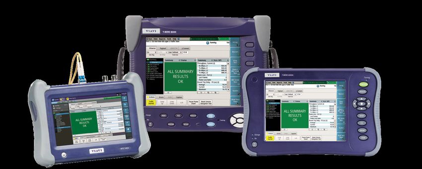
The CBS test and the TrueSpeed test described in this application note are integrated into the RFC 2544 and Y.1564
automated workflows on the T-BERD/MTS-5800 and the T-BERD/MTS-6000A and -8000 MSAM, shown here in
Figure 27.
Finding network misconfigurations:
Test Measuring (kBytes) Type of Problem Benefit
Buffer Reduce
CBS Burst
Configuration Frame Loss
Size
Ensuring service performance:
Test Measuring (kBytes) Type of Problem Benefit
Customer Eliminate
RFC 6349 Application Experience Finger
TrueSpeed Throughout and QoS Pointing
Figure 26. Integrated burst testing methodology
Figure 27. VIAVI Metro Family
Contact Us +1 844 GO VIAVI © 2021 VIAVI Solutions, Inc.
(+1 844 468 4284) Product specifications and descriptions in this
document are subject to change without notice.
To reach the VIAVI office nearest you, burstingtest-an-tfs-tm-ae
visit viavisolutions.com/contacts. 30173394 902 0121
viavisolutions.comYou can also read