Active EMI Suppression with Adapted Cancellation Signals for a Buck Converter in Varying Modes of Operation - TU Dortmund
←
→
Page content transcription
If your browser does not render page correctly, please read the page content below
Active EMI Suppression with Adapted Cancellation Signals for a
Buck Converter in Varying Modes of Operation

Tobias Dörlemann1, Andreas Bendicks1, Stephan Frei1
1
    On-board Systems Lab, TU Dortmund University, Germany

Corresponding author: Tobias Dörlemann, tobias.doerlemann@tu-dortmund.de

Abstract
Many modern power electronic systems make use of fast switching semiconductors for energy
conversion and distribution. Steep switching slopes for high efficiencies may cause high levels of
electromagnetic emissions. Conducted emissions are conventionally reduced by applying heavy and
bulky passive filter components. The basic concept of active filtering aims at a destructive interference
between the emissions (noise) and a generated anti-noise signal and is one idea to overcome the
disadvantages of passive filter components. In this contribution, a self-adapting, FPGA-based active EMI
cancellation system using artificially synthesized cancellation signals is investigated for the first time
during a buck converter’s transient changes in operation.

1 Introduction                                           occurs. For a stable destructive interference, noise
                                                         and anti-noise signals must be synchronized by
Fast-switching power electronic converters can be        appropriate means. Since the fit between these
significant      sources         of    electromagnetic   signals is significantly improved by this measure,
interferences (EMI). To reduce the EMI and to            high EMI reductions can be achieved in a wide
comply      with    international      standards    in   frequency range [6].
electromagnetic      compatibility       (EMC),   e.g.
                                                         One approach to realize an active cancellation
CISPR 25 for vehicles [1], passive filter
                                                         system with synthesized and synchronized signals
components are conventionally applied [2].
                                                         is to use methods in frequency domain. In e.g. [7],
Because these passive filter components usually
                                                         the anti-noise signal is calculated by measuring
suffer from their high weight and volume, active
                                                         and identifying the noise signal with the help of an
EMI filtering concepts (e.g. [3] – [5]) have been
                                                         off-line fast fourier transform (FFT) and taking the
elaborated that aim for a destructive interference
                                                         transmission path’s influence on the injected anti-
between noise and anti-noise signals.
                                                         noise signal into account. Because of the needed
To yield a stable destructive interference, the anti-    calculation time, this method requires periodic
noise signal must equal the noise signal with            noise signals and a perfect synchronization
opposite sign. Therefore, in feedforward and             between noise and anti-noise signal source. This
feedback active filtering concepts, noise signals        system is well suited to show the potential of using
are measured, inverted, amplified and back-              synchronized and synthesized cancellation
injected as anti-noise signals. Due to time              signals, but it is limited by its requirement of
constants and unavoidable signal propagation             periodic noise signals.
delays, the perfect fit between noise and anti-noise
                                                         Another approach are single-frequency adaptive
signals is limited. Accordingly, the achievable
                                                         notch filters that have originally been designed for
noise suppression is also limited [6].
                                                         active noise cancellation approaches in the
By     injecting    artificially    synthesized   and    acoustic domain (e.g. [8] – [9], [15]). Here, the anti-
synchronized anti-noise signals, the limiting            noise signal is artificially synthesized from sine
influence of time constants and signal propagation       waves that shall suppress the corresponding
delays can be compensated. Time constants can            harmonic of the noise signal (e.g. [10] - [12]). By
be compensated by shaping the anti-noise signals.        adaptively adjusting the amplitudes and phases of
Signal propagation delays can be compensated by          each sine wave, the influence of time constants
injecting the anti-noise signals before the noise        and signal propagation delays can be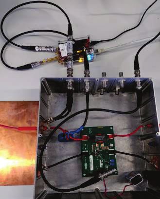
compensated. This adjustment can be done by interfere with the corresponding noise signal
appropriate optimizers that observe the residual frequency components.
noise (superposition of noise and anti-noise). In Fig. 1, an ideal time-discrete single-frequency
Multiple harmonics of the noise can be adaptive notch filter algorithm is depicted. An
compensated by applying a set of notch filters in orthogonal system is created by synthesizing an
parallel and superposing all anti-noise sine waves. arbitrary time-discrete cosine signal ݔ ሺ݊ሻ and an
In, e.g., [10] - [12], the single-frequency adaptive arbitrary time-discrete sine signal ݔଵ ሺ݊ሻ with
notch filter is applied to a buck converter with frequency ݂ in parallel. Both reference signals
constant load and supply conditions, constant duty ݔ ሺ݊ሻ and ݔଵ ሺ݊ሻ are multiplied by a weighting factor
cycle and constant switching frequency. In [13] and ݓ ሺ݊ሻ or ݓଵ ሺ݊ሻ, respectively. Subsequently, the
[14], it is applied to a power factor correction resulting products are superimposed and inverted
(PFC). In this application, the duty cycle varies with to form the anti-noise signal ݕሺ݊ሻ. By adapting the
the mains’ voltage, but all other conditions are still filter weights in every single time step as shown in
constant. These investigations show the (1) and (2), the resulting anti-noise signal ݕሺ݊ሻ can
performance of the method during stationary be adjusted in amplitude and phase. This
modes of operation, but practical systems are also adaptation is achieved with help of the Least Mean
exposed to transient changes. Since the EMC Square (LMS) algorithm that bases on the concept
must also be fulfilled during such dynamic modes of gradient descent.
of operation, they are investigated in this work. A
buck converter will be used as an exemplary ݓ ሺ݊ ͳሻ ൌ ݓ ሺ݊ሻ ߤ ݁ ڄሺ݊ሻ ݔ ڄ ሺ݊ሻ (1)
demonstrator. The following abrupt changes will
be investigated: ݓଵ ሺ݊ ͳሻ ൌ ݓଵ ሺ݊ሻ ߤ ݁ ڄሺ݊ሻ ݔ ڄଵ ሺ݊ሻ (2)
- Turn-on of the active cancellation system,
- Change of the buck converter’s duty cycle, In [8, 9], the ͳȀ݁ time constant ߬ of the adaptation
- Change of the buck converter’s load. process is approximated under ideal assumptions
and is given in (3). Here, ܶ௦ represents the sample
At first, the fundamental theory of single-frequency time of the time-discrete system, while ܣ
adaptive notch filters is explained in Section 2, represents the amplitude of both reference signals
while the FPGA-based realization of the active EMI ݔ ሺ݊ሻ and ݔଵ ሺ݊ሻ (in this work: ܣൌ ͳ). The step size
cancellation system and the test setup are parameter ߤ determines the adaptation speed of
described in Section 3 and Section 4, respectively. the algorithm. While a smaller step size ߤ results
In Section 5, the dynamic behavior of the adaptive in more precise results, a larger step size enables
notch filter implementation is investigated with help
a faster adaptation.
of time-domain measurements and spectrograms.
In Section 6, the limits and potentials of the method ʹܶୱ
(3)
are investigated with the help of EMI receiver ߬
ߤܣଶ
measurements. Finally, a conclusion and an Hence, regarding dynamic noise signals, a bigger
outlook are given in Section 7. step size ߤ is beneficial to follow the changes.
Nevertheless, if the step size ߤ is chosen too large,
2 Theory of single-frequency the anti-noise signal’s precision can be noticeably
reduced, or the adaptive notch filter can even
adaptive notch filters become unstable. A stability analysis of ideal
Adaptive notch filters can be classified as adaptive notch filters can be found in, e.g., [9].
narrowband feedforward active noise control Single-frequency adaptive notch filter
(ANC) systems and have been extensively
examined in acoustics, e.g. [8] and [9]. + -1
Anti-noise
The concept of adaptive notch filters bases on the
digital synthesis of a sinusoidal signal (cancelling
sine wave) for every noise signal frequency to be Residual
mitigated. At every instant of time, all cancelling noise
sine waves in parallel are adapted in amplitude LMS algorithm
and phase, superimposed, digital-to-analog- Fig. 1: Single-frequency adaptive notch filter with
converted and injected as an anti-noise signal. LMS algorithm.
This anti-noise signal is intended to destructively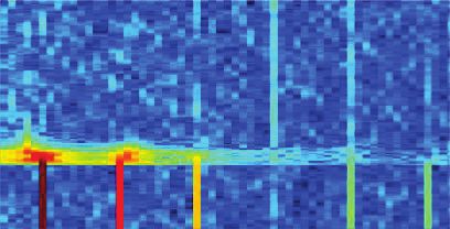
In practical applications, the noise and anti-noise With help of a sensing circuit, the residual noise
signals are not directly superimposed. The anti- signal is measured between the EMI source and
noise signal must first be digital-to-analog the EMI sink. The measured residual noise signal
converted and injected. Then, it propagates is analog-to-digital-converted and passed to the
through the overall system and superposes itself FPGA-implementation of the six parallel adaptive
with the noise. The resulting residual noise must notch filters. Each adaptive notch filter synthesizes
be sensed and analog-to-digital converted. So, the an anti-noise orthogonal system and optimizes its
complex transfer function for the anti-noise signal weighting factors to minimize the residual noise
path contains time constants and delay times. This regarding its considered anti-noise frequency. The
transfer function influences the adaptive notch anti-noise frequencies of all six adaptive notch
filter’s behavior in real applications and has to be filters in parallel are superimposed inside the
considered in the design of the algorithm. FPGA logic to form the anti-noise signal. This anti-
Especially the resulting delay time for each noise signal is passed through the digital-to-
cancelling sine wave (that also comprises phase analog-converter and injected into the system.
shifts) is critical for the stability of the algorithm. FPGA-Implementation
To avoid instabilities due to this delay time, the Notch Filter
at
adaptive notch filter’s LMS algorithm is …
implemented as a delayed LMS (DLMS) algorithm + Notch Filter
([9] and [16]) as shown in (4) and (5). In this at
Notch Filter
adaptation process, ȟ is an estimation of the at
corresponding delay time.
DAC ADC
ݓ ሺ݊ ͳሻ ൌ ݓ ሺ݊ሻ ߤ ݁ ڄሺ݊ሻ ݔ ڄ ሺ݊ െ ȟሻ (4)
ݓଵ ሺ݊ ͳሻ ൌ ݓଵ ሺ݊ሻ ߤ ݁ ڄሺ݊ሻ ݔ ڄଵ ሺ݊ െ ȟሻ (5) EMI source Injector Sensor EMI victim
To ensure the stability of the adaptive notch filter,
the error between the estimation ȟ and the actual Fig. 2: Topology of the FPGA-based active EMI
delay time must be smaller than േͻͲι [8, 9]. In cancellation concept.
case of an estimation error smaller than േͶͲι, the
convergence speed of the algorithm is theoretically
only slightly affected [9, 17]. 4 Test setup: DC/DC buck
Regarding the convergence speed of the converter
algorithm, the time delay between anti-noise signal
synthesis and residual noise signal measurement The following investigations make use of a test
should be as short as possible to reduce the notch setup consisting of a 48 V / 12 V buck converter
filter’s dead time. powered by a 48 V voltage source and driving an
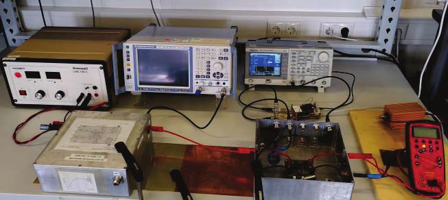
ohmic load. The schematic can be found in Fig. 3.
Photographs of the of the overall test setup and the
3 FPGA-based realization of the inside of the Device Under Test’s (DUT) box can
be found in Fig. 4 and Fig. 5.
active EMI cancellation system
An arbitrary function generator is used to generate
In this work, an FPGA development board Red the buck converter’s trapezoidal control signal with
Pitaya STEMlab 125-14 is used as a hardware a fundamental frequency of ݂ ൌ ͵ͲͲ . To
basis for the active EMI cancellation system. This enable a standardized measurement of the
development board provides fast analog-to-digital resulting noise voltage, an artificial network is
and digital-to-analog converters with a sample rate placed between the 48 V voltage source and the
of 125 MS/s and a vertical resolution of 14 bit in buck converter (according to CISPR 25, [1]). For
combination with a Field-Programmable Gate evaluation purposes, the resulting noise signal is
Array (FPGA). The used FPGA-based measured by an oscilloscope with 50 Ω-
implementation comprises six single-frequency termination or an EMI receiver (that intrinsically
adaptive notch filters with DLMS-adaptation has a termination of 50 Ω) at the artificial network’s
algorithm in parallel, as illustrated in Fig. 2. In this measurement port.
work, all six adaptive notch filters are parametrized The FPGA-based adaptive notch filter
with the same step size ߤ. implementation is realized as described in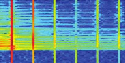
Section 3. For each of the control signal’s first six 5 Time-domain measurements
harmonics (݂ ൌ ͵ͲͲ ǡ ǥ ǡ ݂ ൌ ͳǤͺ ), one
of the six parallel adaptive notch filters synthesizes during transient changes of the
a cancelling sine wave. For adaptation purposes, buck converter’s operation
the residual noise signal is measured, while the
nominal voltage of 48 V is blocked by a capacitor. To evaluate the performance of the FPGA-based
To prevent an overdrive of the ADC due to high- active EMI cancellation system during the buck
frequency components (that are not actively converter’s transient changes in operation, the
cancelled out), a low-pass filter is applied. To resulting spectrogram of the residual noise will be
dampen resonances, a 3 dB attenuator is added. determined. Hereby, the residual noise spectrum
The generated anti-noise signal is digital-to- is visualized over time.
analog-converted and injected into the test setup
using an inductive coupler. A possible DC-offset of 5.1 Spectrogram calculation for
the anti-noise signal is blocked by a capacitor. evaluation purposes
Further details regarding the used sensing and Because of the fast changes of the buck
injecting circuits can be found in [12]. converter’s operation modes, the determination of
Artificial
network
Sensor Injector DC/DC converter
(buck converter)
Ohmic
load
the (residual) noise signal’s spectrogram is
challenging. Due to the relatively slow
measurement with help of common frequency-
domain measurement equipment (e.g. EMI test
ADC
Low-
pass
Attenuator DAC receivers), the (residual) noise signal is initially
measured in time domain with the help of an
FPGA-based Control oscilloscope. Afterwards, the spectrogram of the
EMI receiver/
adaptive notch filter
implementation
signal
synthesis residual noise signal is determined by the
oscilloscope
subsequent and successive calculation of the Fast
Fig. 3: Schematics of the test setup. Fourier Transform (FFT) of several time segments
of the measured residual noise signal as illustrated
in Fig. 6. To do so, a time window of the measured
EMI receiver
(or oscilloscope) Control signal
residual noise signal is selected
Voltage source
(48V) synthesis (ܶ୧୬ୢ୭୵ ൌ ͳͲȀ݂ ), its FFT is calculated and
FPGA assigned to the end time ݐ୬ୢ of the regarded time
board Ohmic
load window. Afterwards, the window is moved forward
to calculate the next FFT. In the spectrogram all
Artificial calculated FFTs are concatenated.
network
DUT
Measured time
Fig. 4: Photograph of the test setup. domain signal
FPGA-board with
ADCs and DACs
Low-pass Currently regarded
signal segment Next regarded
Attenuator signal segment
DC-block
DC-block
Inductive
transducer
Fig. 6: Illustration of the spectrogram calculation.
Control
signal
5.2 Performance analysis during the
DC/DC converter
(buck converter) switch-on of the adaptive notch filters
To examine the dynamic performance of the
Fig. 5: Photograph of the inside of the DUT box.
adaptive notch filter implementation, the noise
suppression is initially analyzed during the switch-
on process of the adaptive notch filter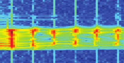
implementation. To do so, the buck converter is switching harmonics are stable for ݐ൏ Ͳ. After the
operating in stationary mode and the (residual) duty cycle has changed, the noise levels stabilize
noise signal is measured at the measurement port again after a short period of time. The centrally
of the artificial network. placed and lower spectrogram in Fig. 8 reveal the
In Fig. 7, the corresponding spectrograms are behavior of the adaptive notch filter
depicted for two different step sizes (ߤ ൌ ͲǤͲͲͲ implementation for the two different step sizes
and ߤ ൌ ͲǤͲͲʹ). At ݐൌ Ͳ, the six parallel adaptive during the variation of the duty cycle. Before the
notch filters are turned on and optimize the duty cycle changes ( ݐ൏ Ͳ), the residual noise
respective cancelling sine waves. The (residual) levels for both step sizes are below the
noise levels at the switching harmonics (harmonics measurement noise level. When the duty cycle
of the switching frequency) decrease faster in case changes at ݐൌ Ͳ, the residual noise levels
of the larger step size ߤ. This observation is increase for every considered switching harmonic
especially noticeable for the switching frequency for both step sizes and temporarily exceed the
݂ ൌ ͵ͲͲ and its first two overtones at corresponding noise levels with disabled notch
ͲͲ and ͻͲͲ , due to their relatively high filters. After the duty cycle changed and the noise
noise levels. signal stabilizes again, both adaptive notch filter
implementations are able to quickly adapt to the
changed noise signal. Here, the implementation
with the larger step size parameter ߤ shows a
enabled
faster adaptation of the anti-noise signal to the
Cancellation
changed noise signal.
disabled
25 %
Duty cycle
enabled
15 %
Cancellation
disabled
25 %
Duty cycle
Fig. 7: Spectrograms of the (residual) noise during
the switch-on process of the adaptive notch
filters for two different step sizes.
15 %
5.3 Performance analysis during an
exemplary change of the control
25 %
signal’s duty cycle
Duty cycle
In the previous examination, the duty cycle of the
buck converter’s control signal has been constant.
15 %
In the following, the performance of the adaptive
notch filter implementation is examined during a
changing duty cycle of the buck converter’s control Fig. 8: Spectrograms of the (residual) noise in a time
signal. The duty cycle is varied between 15 % and frame around the jump of the duty cycle of
25 % and comes along with a changing DC voltage the buck converter’s control signal.
at the ohmic load.
In the upper spectrogram in Fig. 8, the adaptive Due to the suddenly changing duty cycle of the
notch filter is turned off, while the duty cycle of the buck converter’s control signal, the noise signal is
buck converter’s control signal changes at ݐൌ Ͳ. changing, too. The previously found filter weights
Obviously, the noise levels of the considered and the corresponding anti-noise signal do not fit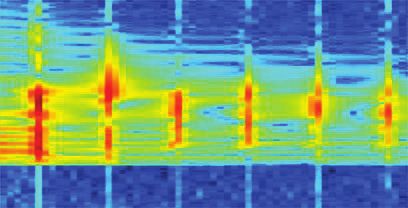
to the noise signal anymore. In consequence, a 6 Frequency-domain
temporary amplification of the noise signal can
occur (constructive interference). As soon as the measurements for transient
noise signal stabilizes, both adaptive notch filter changes of the buck converter’s
implementations quickly accomplish a significant
noise reduction again (destructive interference). operation
The spectrograms in the previous sections are
helpful to investigate the dynamic behavior of the
5.4 Performance analysis during an adaptive notch filters. But finally, the method has
exemplary change of the load to be evaluated with the help of EMI receiver
measurements according to common EMC
resistance standards that are carried out and discussed
In the previous examinations, the load resistance below.
of the buck converter is kept constant at 1 Ω. Now, The previously shown analysis reveals that the
the load resistance at the 12 V-side of the buck examined adaptive notch filters may follow slowly
converter initially equals 2 Ω, but, around ݐൌ Ͳ, changing noise signals. In contrast, sudden
the load resistance is changed from 2 Ω to 1 Ω. changes of the noise signal - e.g. caused by a
In case of the upper spectrogram in Fig. 9, the suddenly changing duty cycle - can push the
adaptive notch filter implementation is disabled, adaptive notch filter implementation to its limits.
while noise levels at the considered switching The variation of the duty cycle of the buck
harmonics are only slightly changing due to the converter’s control signal can be realized in
changing load resistor. The spectrogram for the different ways and is therefore suitable for a further
enabled notch filter implementation with the analysis of the notch filter’s adaptation limits. In the
smaller step size of ߤ ൌ ͲǤͲͲͲ reveals stable following investigation, the duty cycle is varied
noise reductions for all considered switching either sinusoidal or rectangular between 15 % and
harmonics before, after and even during the 25 % as illustrated in Fig. 10. The sinusoidal
changing of the load resistance. Similar results variation of the duty cycle comes along with a more
have been found for ߤ ൌ ͲǤͲͲʹ. In case of the continuously changing noise signal, while the
changing load resistor, the disturbances seem to rectangular variation of the duty cycle causes
change more slowly compared to the case of the sudden changes of the noise signal. By varying the
suddenly changing duty cycle from 15 % to 25 %. modulation frequency ݂୭ୢ୳୪ୟ୲୧୭୬, the incidence of
In consequence, the adaptation process can follow the larger and sudden duty cycle changes can be
the changing noise signal, and the adaptive notch varied, while in case of the sinusoidal variation of
filters are able to achieve a sustained high noise the duty cycle, the speed of the duty cycle’s
suppression. alteration can be varied.
Load resistance
Fig. 10: Sinusoidal and rectangular variation of the
buck converter’s duty cycle.
In the following, the frequency of the sinusoidal or
Load resistance
rectangular duty cycle modulation is varied
between 100 mHz and 1 kHz. The buck converter
is in operation and the adaptive notch filter is
implemented with a step size ߤ ൌ ͲǤͲͲʹ. For
evaluation purposes, the noise signal (disabled
notch filters) and the residual noise voltages
Fig. 9: Spectrograms of the (residual) noise before
(enabled notch filters) are measured at the artificial
and after the load resistance change.
network’s measurement port by an EMI receiver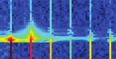
with 9 kHz resolution bandwidth and 20 seconds above a modulation frequency of 10 Hz.
measurement time (so that at least two full cycles Nonetheless, even at the higher switching
of the modulation are measured). The harmonics and the highest regarded modulation
measurement is done with an average and a peak frequency (1 kHz), the achieved noise reduction is
detector. nearly 20 dB for the average- and peak- rated
In Fig. 11, the realized noise reductions at the six emissions.
considered switching harmonics are depicted for
five different modulation frequencies ݂୭ୢ୳୪ୟ୲୧୭୬.
The depicted noise reductions relate to either a
sinusoidal (blue, yellow) or rectangular (violet,
green) modulation of the duty cycle. The noise
reductions in dB are calculated by subtracting the
(residual) noise levels, measured at the observed
switching harmonics.
In case of the rectangular modulation of the duty
cycle, the peak-rated noise reductions are
significantly lower than for the measurements with
average-detector. Due to the sudden changes of
the noise signal, the anti-noise signal does
temporarily not fit to the noise signal anymore, as
described in detail in Section 5.3. In consequence,
the noise signal can be momentarily amplified Fig. 11: Noise reductions at the switching harmonics
(constructive interference), such that the residual for different modulation frequencies.
noise level exceeds the noise level. This
momentary amplification is captured by the peak
detector measurement of the residual noise signal.
In consequence, the determined noise reduction in 7 Conclusion and Outlook
peak-mode is vanishingly small (300 kHz, In this work, an FPGA-based adaptive notch filter
600 kHz), or even negative (900 kHz – 1.8 MHz). has been examined during different transient
The peak detector finds the highest value during changes of a buck converter’s operation mode,
the measurement time without considering the e.g. a suddenly changing duty cycle of the control
repetition rate of the disturbance. So, the peak- signal, or a changing load resistance.
rated values are independent from the modulation Suddenly changing noise signals, e.g. caused by
frequency. After the abrupt changes, the adaptive a suddenly changing duty cycle of the control
notch filters have quickly adapted the anti-noise signal, can push the adaptive notch filter to its
signal and a significant noise reduction is achieved limits and may cause a temporary amplification of
most of the time. Consequently, a significant noise the noise signal. This suddenly changing noise
reduction is determined by measuring the signal does not fit to the previously found anti-
average-rated (residual) noise signals. The higher noise signal anymore and the adaptation process
the modulation frequency is chosen, the more needs some time to fit the anti-noise signal to the
often the duty cycle changes and the more often a changed noise signal again.
temporary amplification of the noise signal occurs.
In consequence, the noise reduction in average- In contrast, a slowly or more continuously
mode decreases with higher modulation changing noise signal allows the adaptive notch
frequency. filters to follow the noise signal’s changes. In case
of a sinusoidal modulation of the duty cycle of the
In case of a sinusoidal modulation of the control buck converter’s control signal, noise reductions of
signal’s duty cycle, the noise reductions e.g. 65 dB (average detector) and 59 dB (peak
determined by measurements with average and detector) have been realized at 300 kHz with a
peak detector are very similar. This indicates that modulation frequency of 10 Hz. The realized noise
the adaptive notch filters can follow the changes of reductions slowly decrease for modulation
the noise signal due to the continuously changing frequencies above 10 Hz, but still reveal the
duty cycle of the control signal. The depicted noise potential of the method with a noise reduction of
reductions for all considered switching harmonics e.g. around 50 dB at 300 kHz and 24 dB at
reveal that the achieved noise reductions are 1.8 MHz with a modulation frequency of 100 Hz.
decreasing with increasing modulation frequency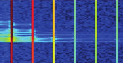
The adaptive notch filter’s ability to follow changing        [9] S. M. Kuo, D. R. Morgan, “Active noise control
noise signals caused by a sinusoidal modulation of                systems – Algorithms and DSP implementations,”
the control signal’s duty cycle suggests the                      New York: Wiley, 1996.
application to inverter systems and will be subject           [10] A. Bendicks, T. Dörlemann, S. Frei, N. Hees, M.
of future investigations.                                          Wiegand, “FPGA-basierte aktive Gegenkopplung
                                                                   der            Schaltharmonischen            von
                                                                   leistungselektronischen Systemen,” in Proc. Conf.
8 References                                                       Electromagn. Compat., Düsseldorf, Germany,
[1] “CISPR 25 – Vehicles, boats and internal                       20 - 22 Feb. 2018, pp. 652-661.
    combustion engines – Radio disturbance                    [11] A. Bendicks, T. Dörlemann, S. Frei, N. Hees, M.
    characteristics – Limits and methods of                        Wiegand, “Development of an adaptive EMI
    measurement for the protection of on-board                     cancellation strategy for stationary clocked
    receivers,” 4th ed., Feb. 2015.                                systems,” in Proc. Int. Symp. Electromagn.
[2] K. Mainali, R. Oruganti, “Conducted EMI mitigation             Compat. Eur., Amsterdam, Netherlands, 27-30
    techniques for switch-mode power converters: A                 Aug. 2018, pp. 78-83.
    Survey,” IEEE Trans. Power Electron., vol. 25, no.        [12] A. Bendicks, T. Dörlemann, S. Frei, N. Hees, M.
    9, pp. 2344-2356, Sep. 2010.                                   Wiegand, “Active EMI reduction of stationary
[3] Y.-C. Son, S.-K. Sul: “Generalization of active filters        clocked     systems     by   adapted    harmonics
    for EMI reduction and harmonics compensation,”                 cancellation,” IEEE Trans. Electromagn. Compat.,
    IEEE Trans. Ind. Appl., vol. 42, no. 2, pp. 545-551,           vol. 61, no. 4, pp.998-1006, Aug. 2019.
    Mar.-Apr. 2006.                                           [13] A. Bendicks, A. Peters, S. Frei, M. Wiegand, N.
[4] N. K. Poon, J. C. P. Liu, C. K. Tse, M. H. Pong:               Hees, “FPGA-basierte aktive Unterdrückung der
    “Techniques for input ripple current cancellation:             elektromagnetischen Störungen einer aktiven
    classification and implementation [in SMPS],” IEEE             Leistungsfaktorkorrektur (PFC) durch die Injektion
    Trans. Power Electron., vol. 15, no. 6, pp. 1144-              von modulierten Sinussignalen,“ in Proc. Conf.
    1152, Nov. 2000.                                               Electromagn. Compat., Cologne, Germany, pp.
[5] B. Narayanasamy, F. Luo, “A survey of active EMI               433-442, 12-13 May 2020.
    filters for conducted EMI noise reduction in power        [14] A. Bendicks, A. Peters, S. Frei, “FPGA-based
    electronic converters,” IEEE Trans. Electromagn.               Active Cancellation of the EMI of a Boost Power
    Compat., vol. 61, no. 6, pp. 2040-2049, Dec. 2019.             Factor Correction (PFC) by Injecting Modulated
[6] A.      Bendicks,     “Active   cancellation    of             Sine Waves,” IEEE Letters on Electromagnetic
    electromagnetic emissions of power electronic                  Compatibility Practice and Applications, vol. 3, no.
    systems by injecting synthesized and synchronized              1, pp.11-14, March 2021.
    signals,” Ph.D. dissertation, On-board Systems            [15] J. R. Glover, Jr., “Adaptive noise canceling applied
    Lab, TU Dortmund University, Dortmund, Germany,                to sinusoidal interferences,” in IEEE Trans. Acoust.,
    2020.               [Online].           Available:             Speech, Signal Process., vol. 25, no. 6, pp. 484-
    https://eldorado.tu-dortmund.de/handle/2003/3921               491, Dec. 1977.
    2?locale=en.                                              [16] E. Ziegler, Jr., “Selective active cancellation system
[7] A. Bendicks, M. Rübartsch, S. Frei, “Simultaneous              for repetitive phenomena,” U.S. Patent 4 878 188,
    EMI suppression of the input and output terminals              31 Oct. 1989.
    of a DC/DC converter by injecting multiple                [17] C. C. Boucher, S. J. Elliott, P. A. Nelson, “Effect of
    synthesized cancellation signals,” in Proc. Int.               errors in the plant model on the performance of
    Symp. Electromagn. Compat. Eur., Barcelona,                    algorithms for adaptive feedforward control,” IEE
    Spain, 2 - 6 Sep. 2019, pp. 842-847.                           PROC-F., vol. 138, no. 4, pp. 313-319, Aug. 1991.
[8] S. M. Kuo, D. R. Morgan, “Active noise control: A
    tutorial review,” Proc. IEEE, vol. 87, no. 6, pp. 943–
    973, Jun. 1999.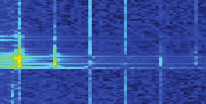
You can also read