Pharos HDTM Surgical High Definition Camera Operating Manual - BFW Inc.
←
→
Page content transcription
If your browser does not render page correctly, please read the page content below
Pharos HD            TM

Surgical High Definition Camera
       Operating Manual
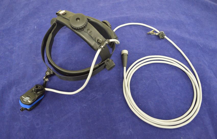
Table of Content
Symbol Description......................................................................................2
Warnings and Cautions.................................................................................3
     Intended Use................................................................................................................ 4
Overview......................................................................................................5
     System Description....................................................................................................... 5
Assembly and Operation..............................................................................6
     Camera......................................................................................................................... 6
     Pharos HDTM Headband................................................................................................ 7
     Setup............................................................................................................................ 8
     Camera Control Unit..................................................................................................... 9
     Linkage Assembly....................................................................................................... 10
     Removing the Headlight............................................................................................. 11
     Mounting the Headlight............................................................................................. 12
Cleaning and Maintenance.........................................................................15
     Camera and Control Unit............................................................................................ 15
Specifications.............................................................................................16
Electromagnetic Compatibility....................................................................17
Troubleshooting and Service......................................................................21
     Troubleshooting.......................................................................................................... 21
     Warranty and Service................................................................................................. 22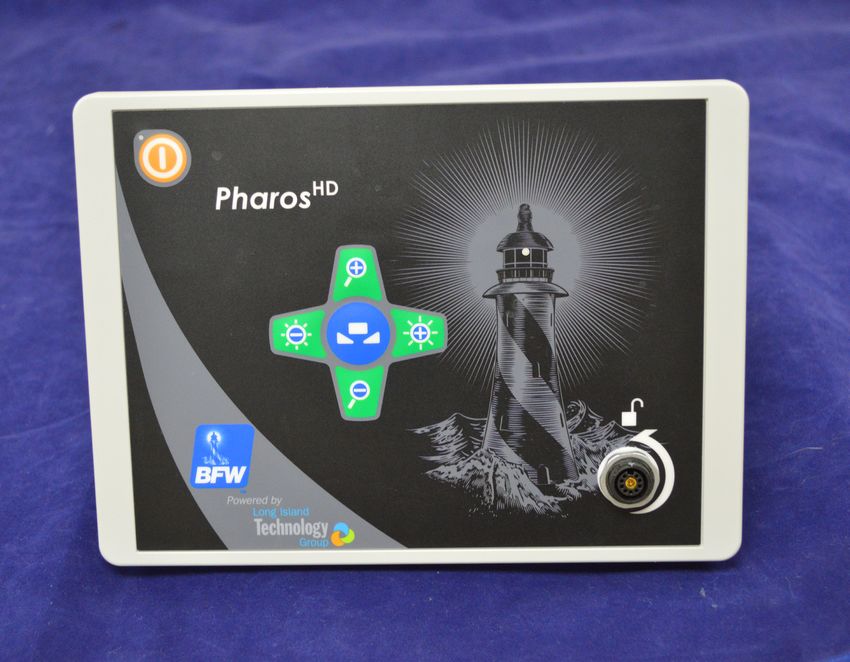
Symbol Description
These important symbols may appear on your Long Island Technology Group Camera. Please note their mean-
ing.

                 Attention: Read this owner’s manual for all warnings, precautions and instructions for use.

                 CE marking of conformity indicates this device complies with European Directive 93/42 EC
                 on medical devices and Directive 2002/95/EC on the restriction of the use of certain hazard-
                 ous substances in electrical and electronic equipment.

                 The UL mark indicates this product has been tested to, and conforms to applicable stan-
                 dards.

                 More information for this product can be found in this operating manual.

                    AS TO ELECTRICAL SHOCK, FIRE AND MECHANICAL HAZARDS ONLY
                             IEC 60601-1 Edition 3, IEC 60601-1-2 Edition 4,
                    ANSI/AAMI E-S60601-1 (2005), CAN/CSA-C22.2 No. 60601-1 (2008)

                                                                                                               2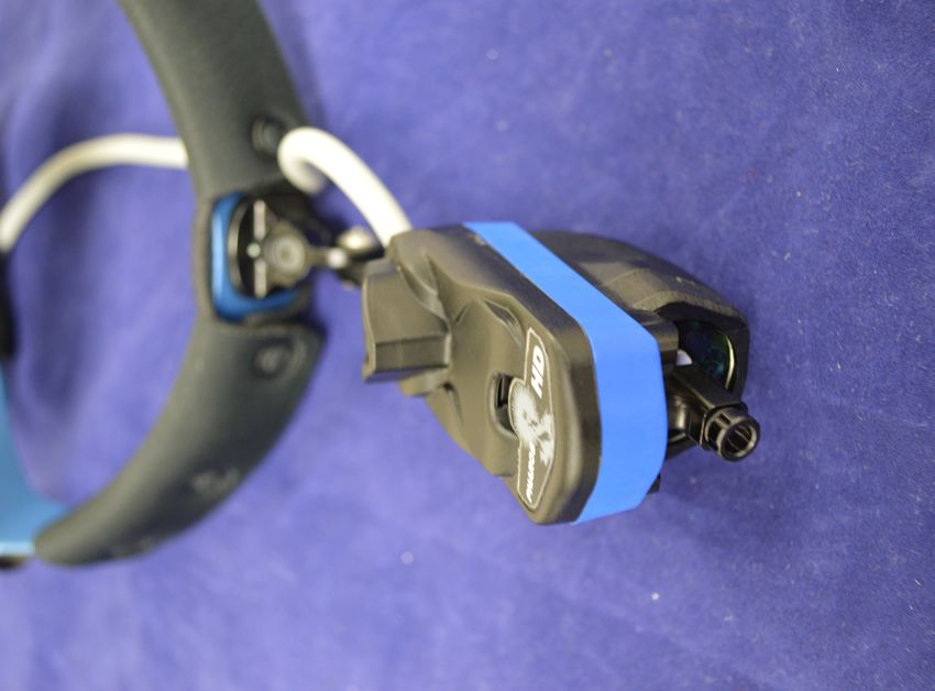
Warnings and Cautions
Users of this product should be thoroughly trained in the appropriate medical procedures. Also they should
read and understand this owner’s manual for this camera and all equipment used with it.

!      Read and understand the Device Operating Manual before using this device

!      DO NOT use if packaging is damaged.

!      Avoid prolonged contact with the camera during use at it may be warm.

!      Standard Working Distance is 16 inches (40 cm) minimum. Use caution when operating at closer dis-
       tances.

!      Use Pharos HDTM only with BFWTM/Long Island Technology GroupTM products or accessories.

!      DO NOT subject the Pharos HDTM to strong shocks, which includes but is not limited to dropping the
       device on the floor.

!      DO NOT use this device for other than its intended use.

!      DO NOT modify this equipment.

!      DO NOT open this device. No serviceable components are inside this device.

!      Only Qualified Personnel should operate the Pharos HDTM

!      DO NOT submerge this device or any of its components in liquid.

!      Stacking or placing close to other equipment may negatively impact EMC compliance.

!      Use only video output devices that have been tested to pass Low voltage regulations (IEC 60950 or IEC
       60601-1). Failure to do so may decrease system performance and could result in non-compliance.

!      USE ONLY components and accessories listed on page 5 of this manual. Failure to do so may decrease
       system performance, may lead to unsafe operation, may negatively affect EMC performance and could
       result in non-compliance and could void the warranty.

                                                                                                               3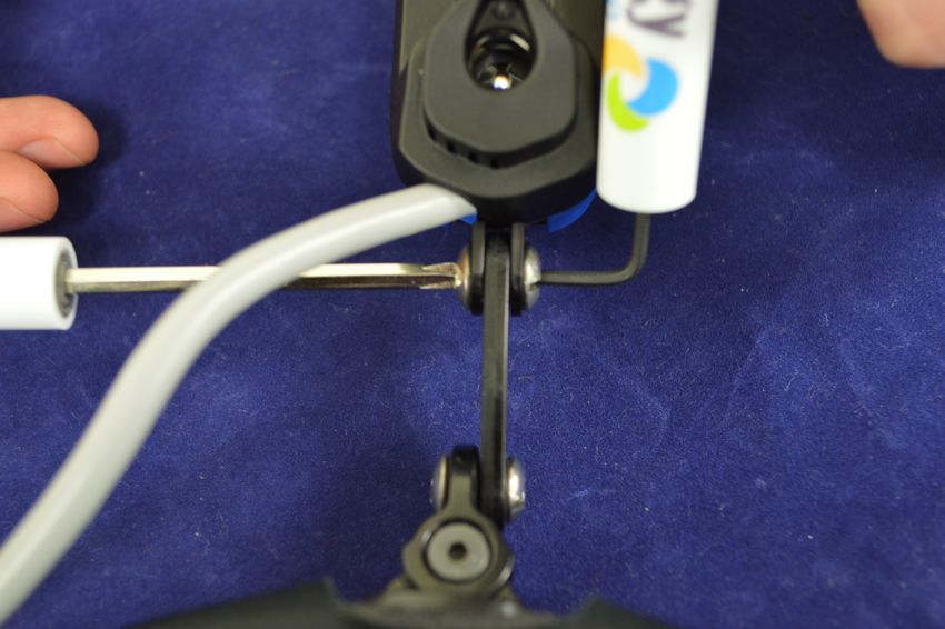
Warnings and Cautions
Intended Use
       The Pharos HDTM Surgical High Definition Camera is a device intended to generate a High Definition vid-
eo image of the area illuminated by a surgical light. The image is intended to be used for remote observation of
the surgeon's view of the surgical field. The unit provides output connectors that allow the image to be dis-
played on remote monitors or connected to a video transmission system for presentation in distant locations.
The intended environment of use is for Professional Health Care.

                                                                                                               4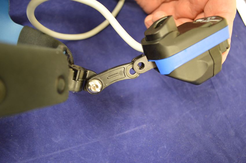
Overview
System Description
        The Pharos HDTM Surgical High Definition Camera system is mounted on a headband. The unit is con-
structed of a durable plastic housing encasing a precision aluminum Lens Holding System with Glass Anti-Re-
flective Coated Lenses and a CMOS high definition 1080p 60 Hz video camera. The camera lens is designed in a
“periscope” configuration so the lens is located exactly in the center of the optics. This ensures that the image
generated by the camera will be aligned with the surgeon's line of sight and the video image presents exactly
what the surgeon sees. The device is articulated on the headband, allowing the camera to be turned left and
right for ease of aiming.

The device is attached to a headband, which allows the medical professional to wear the camera on their head.
The headband mounting system adjusts for comfortable fit and allows the camera to be adjusted for position
between the user's eyes. The device also allows for adjustment to the cameras focus simply by rotating the Fo-
cus Adjustment lens. For information on how to use the Phaors HDTM with approved accessories see the Pharos
HDTM Accessories Manual.

                                        E                                      C

                             B                      A                            D
     A.   Pharos HDTM Camera
     B.   Camera Cable
     C.   Control Unit
     D.   AC Cable
     E.   Pharos HDTM Headband

                                                                                                                5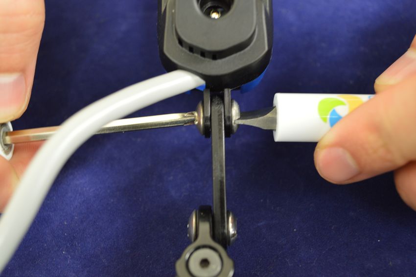
Assembly and Operation
Camera

                                                                                           B
                  C
                                                                                     A

   A.   Camera Periscope
   B.   Focus Adjustment
   C.   Mounting Linkage

                                             Camera Operation:
 1. The camera can be turned a small amount to the left and right to facilitate aiming the camera.
 2. The Mounting Linkage (C) is adjustable for vertical aiming and position adjustment.
 3. Camera focus can be adjusted by rotating the Focus Adjustment (B).

                                                                                                     6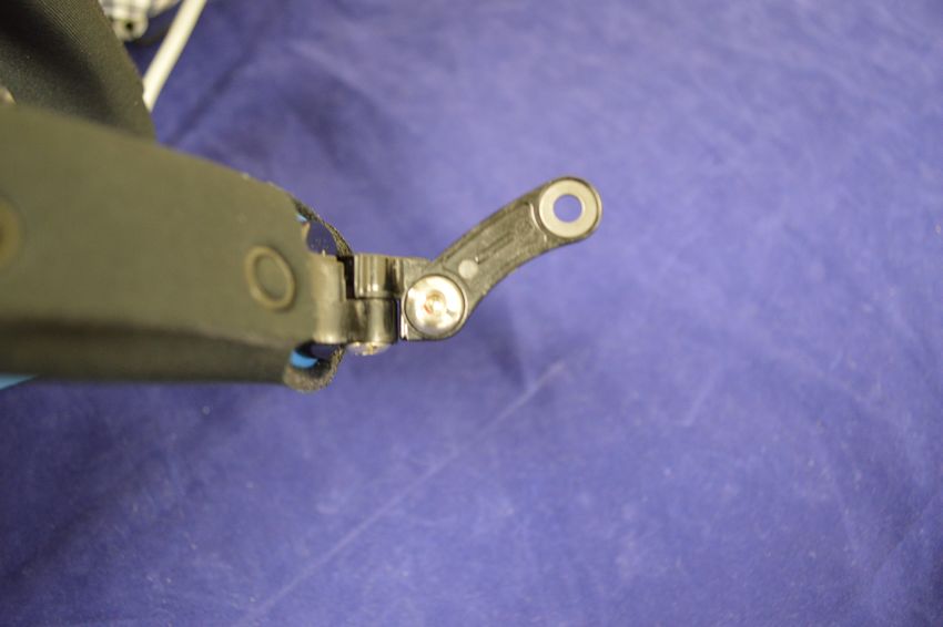
Assembly and Operation
Pharos HDTM Headband
                                              B
                                                                      A
             C

                                                    C

   A.   Gown Clip
   B.   Headband Adjustment Knobs
   C.   Bar Adjustment Knobs
                                             Directions For Use:
 1. Turn the Headband Adjustment Knobs (B) to adjust the headband's fit.
 2. Loosen the Bar Adjustment Knobs (C) in order to raise or lower the position of the bar.
 3. Attach the Gown Clip (A) to help support the camera cable and keep it off the floor.

                                                                                              7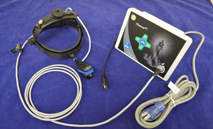
Assembly and Operation
Setup
                                                      D           C

                                                                                                       F

                                                                                                        G

                   A                  B                       E

A. Camera Cable                      E. AC Cable
B. Video Cable                       F. HDMI Out
       HDMI (shown above)            G. SDI Out
       SDI (not shown)               H. AC Power Receptacle                                                H
C. Camera Cable Connector
D. Control Unit

                                              Directions For Use:
  1. Connect the Camera Cable (A) from the Pharos HDTM into the Control Unit (D).
  2. Connect the female end of the AC Cable (E) into the AC Power Receptacle (H) on the Control Unit (D).
  3. Plug the male end of the AC Cable (E) into an AC outlet.
  4. Flip the main power switch into the on position on the AC Power Receptacle (H).
  5. Connect the Video Out (F or G) of the Control Unit (D) into a recorder or monitor.
  6. At this point you should see the camera's image on your display. If you do not please turn to page 21 for
     Troubleshooting.

                                                                                                                 8
Assembly and Operation
Camera Control Unit
F
A
G
B
E
C
D H
A. On/Off E. Brightness decrease
B. Zoom in F. White Balance
C. Zoom out G. White Balance Indicator
D. Brightness Increase H. Camera Cable Connector
Front Panel Controls:
1. Plug the Camera Cable into the Camera Cable Connector (H).
2. Press the On/Off button (A) to turn the Pharos HDTM on, the indicator LED will turn green.
3. The camera will white balance after the White Balance (F) button is pressed. Aim the camera at a white
surface while the White Balance Indicator (G) is flashing.
4. Once the camera has been white balanced the White Balance Indicator (G) will be solid.
5. Pressing the Zoom In (B) or Zoom Out (C) buttons will zoom into or out of the image respectively.
6. Pressing the Brightness Increase (D) or Brightness Decrease (E) will increase or decrease the brightness of
the video respectively.
7. Press the On/Off button (A) again to turn the Pharos HDTM off, the indicator LED will turn red.
NOTE: The Control Unit will turn off if no camera is connected.
9Assembly and Operation
Linkage Assembly
E
A
G H
F C D
B
A. Headband
B. Pharos HDTM
C. Bolt
D. Barrel
E. Washer
F. Set Screw
G. Flathead Screwdriver
H. Allen Wrench
! DO NOT use Thread Locking Glue on the Linkage. Can cause irreparable damage to Linkage leading to a
hazardous situation.
10Assembly and Operation
Removing the Headlight
1. Using the Allen Wrench and Phillips head screwdriver to unlock the binding post.
2. Use the flathead screwdriver and Phillips head screwdriver to unscrew the binding post.
11Assembly and Operation
Mounting the Headlight
3. Place a washer on both sides of the linkage with the concave side towards the linkage.
4. Place the linkage, with washers, between the fork bar.
12Assembly and Operation
5. Place the barrel through the right side of the fork bar.
6. Thread the bolt into the left side of the fork bar and tighten the binding post with the flathead and Phillips
screwdriver.
13Assembly and Operation
7. Place the set screw inside the barrel and tighten it using the Allen Wrench and Phillips screwdriver.
14Cleaning and Maintenance
Camera and Control Unit
1. Clean the Pharos HDTM components with an alcohol wipe.
2. Only use a lens cloth or lens paper on the surface of the optic lens.
3. Use a can of compressed air to clean out any dust accumulations.
4. Clean the Control Unit using alcohol wipes.
! DO NOT pour cleaning solution directly on the surface of the Pharos HDTM.
! DO NOT use any sterilization process or cleaning process using excessive heat or humidity as it will
damage the device.
! NEVER immerse the unit in any type of liquid.
NOTE. Damaging any part of the system with the use of improper cleaning agent or cleaning process will void
all warranties.
15Specifications
Classification
Classification & Type Class I: Medical Accessory, General Medical Equip-
ment as to fire and mechanical hazards
Mechanical
Camera
LxWxH 3.00” x 1.25” x 2.50”
Weight 60g
Pharos HDTM Control Unit
LxWxH 4.00” x 9.00” x 6.00”
Weight 1.25kg
Electrical
Camera
Input Voltage 5 VDC
Input Power 5 Watts Max
Pharos HDTM Control Unit
Input Voltage 110/240 VAC 50/60Hz
Input Power 30 Watts Max
Environment
Operation 60 Degrees F (15.5 C) to 80 Degrees F (26.7 C)
Storage 32 Degrees F (0 C) to 104 Degrees F (40 C)
Relative Humidity 45% - 75%
Pressure/Altitude 860 - 1,060 hPa/2,000m
Video Output
Resolution 1920 x 1080 (1080p)
Frame Rate 60
Interfaces HDMI, SDI
16Electromagnetic Compatibility
Portable and mobile RF communications equipment can affect medical electrical equipment
Guidance and manufacturer’s declaration-electromagnetic emissions
The Pharos HDTM
is intended for use in the electromagnetic environment specified below. The customer or the user of the Pharos
HDTM should assure that it is used in such an environment
Immunity IEC 60601 Test
Compliance Level Electromagnetic Environment Guidance
Test Level
Portable and mobile RF communications equipment should be used no
closer to any part of the Pharos HDTM, including cables, than the recom-
mended separation distance calculated from the equation application to
the frequency of the transmitter.
Recommended Separation Distance:
Battery Operated Device
3 Vrms d = 1.17√P
Conducted
RF IEC 3 VRms 150kHz - 80
3V/m from d = 1.17√P 80 MHz to 800 MHz
61000-4-6 MHz
30MHz to 1GHz,
3V/m for 1 GHz to d = 2.23√P 800 MHz to 2.5 GHz
Radiated 3V/meter 80 MHz -
25GHz; (1000 Hz
RF IEC 2.5 GHz
80% Modulated Where P is the maximum output power rating of the transmitter in
61000-4-3
Test Signal) watts(W) according to the transmitter manufacturer and d is the recom-
mended separation distance in meters (m).
Field strengths from fixed RF transmitters, as determined by an electro-
magnetic site survey (1), should be less than the compliance level in each
frequency range (2).
Interference may occur in the vicinity of equipment marked with the
following symbol:
17Electromagnetic Compatibility
NOTE 1: At 80 MHz, the separation distance for the higher frequency range applies.
NOTE 2: These guidelines may not apply in all situations. Electromagnetic propagation is affected by absorption and reflection from
surfaces, objects, and people.
(1) Field strengths from fixed transmitters, such as base stations for radio (cellular/cordless) telephones and land mobile radios, am-
ateur radio, AM and FM radio broadcast and TV broadcast cannot be predicted theoretically with accuracy to asses the electromag-
netic environment due to fixed RF transmitters, an electromagnetic site survey should be considered. If the measured field strength
in the location in which the Pharos HDTM is used exceeds the applicable RF compliance level above, the Pharos HDTM should be
observed to verify normal operation. IF abnormal performance is observed, additional measure may be necessary, such as re-orient-
ing or relocating the Pharos HDTM.
(2) Over the frequency range 150kHz to 80MHz, field strengths should be less than 3 V/m.
Recommended separation distances between portable and mobile RF communications equipment and the Pharos HDTM
The Pharos HDTM is intended for use in an electromagnetic environment in which radiated RF disturbances are controlled. The
customer or user of the Pharos HDTM can help prevent electromagnetic interference by maintaining a minimum distance between
portable and mobile RF communications equipment (transmitters) and the Pharos HDTM as recommended below, according to the
maximum output power of the communications equipment.
Rate maximum output power Separation distance according to frequency of transmitter in meters
of transmitter
W 150 kHz to 80 MHz 80 MHz to 800 MHz 800 MHz to 2.5 GHz
d = 1.17 P d = 1.17 P d = 2.23 P
.01 0.12 0.12 0.23
.1 0.37 0.37 0.737
1 1.17 1.17 2.33
10 3.70 3.70 7.37
100 11.70 11.70 23.30
For transmitters rated at a maximum output power not listed above, the recommended separate distance d in meters (m) can be esti-
mated using the equation applicable to the frequency of the transmitter, where P is the maximum output power rating of the trans-
mitter in watts (W) according to the transmitter manufacturer.
NOTE 1: At 80 MHz and 800 MHz, the separation distance for the higher frequency range applies.
NOTE 2: The ISM (industrial, scientific and medical) bands between 150 kHz and 80 MHz are 6.765 MHz to 6.795 MHz; 13.553
MHz to 13.567 MHz; 26.957 MHz to 27.283 MHz; and 40.66 MHz to 40.70 MHz.
NOTE 3: An additional factor of 10/3 has been incorporated into the formulae used in calculated the recommended separation dis-
tance for transmitters in the ISM frequency bands between 150 kHz and 80 MHz and in the frequency range 80 MHz to 2.5 GHz to
decrease the likelihood that mobile/portable communications equipment could cause interference if it is inadvertently brought into
patient areas.
NOTE 4: These guidelines may not apply in all situations. Electromagnetic propagation is affected by absorption and reflection from
surfaces, objects, and people.
18Electromagnetic Compatibility
Guidance and manufacturer’s declaration - electromagnetic immunity
The Pharos HDTM is intended for use in the electromagnetic environment specified below. The customer or the end user of the Phar-
os HDTM should assure that it is used in such an environment.
Immunity test IEC 60601 test level Compliance level Electromagnetic environment - guidance
Radiated RF elec-
tromagnetic field
& Proximity fields IEC 61000-4-3 IEC 61000-4-3
from RF wireless
communications Radiated: 80MHz to Radiated: 80MHz to Radiated RF levels should be that of a typical
equipment 2700MHz at 3V/m 2700MHz at 3V/m commercial or hospital environment
IEC 61000-4-6 IEC 61000-4-6
Conducted: 150kHz to Conducted: 150kHz to
Conducted Distur- 80MHz at 3Vrms outside the 80MHz at 3Vrms outside the
bances induced by ISM band, 6Vrms in the ISM ISM band, 6Vrms in the ISM Mains power quality should be that of a typi-
RF fields band band cal commercial or hospital environment.
Floors should be wood, concrete or ceramic
tile. If floors are covered with synthetic ma-
IEC 61000-4-2 IEC 61000-4-2 terial, the relative humidity should be at least
30 %. The user of the (Pharos HDTM) should
Electrostatic dis- ± 8 kV contact ± 8 kV contact avoid situations that could result in excess
charge (ESD) ± 15 kV air ± 15 kV air electrostatic discharge.
IEC 61000-4-4 IEC 61000-4-4
Electrical Fast Tran- ± 2 kV for power supply lines ± 2 kV for power supply lines Mains power quality should be that of a typi-
sient/burst ± 1 kV for input/output lines ± 1 kV for input/output lines cal commercial or hospital environment.
IEC 61000-4-5 IEC 61000-4-5
± 1 kV line(s) to line(s) ± 1 kV line(s) to line(s) Mains power quality should be that of a typi-
Surge ± 2 kV line(s) to earth ± 2 kV line(s) to earth cal commercial or hospital environment.
IEC 61000-4-11 IEC 61000-4-11
95 % dip in UT) 95 % dip in UT)
for 0.5 cycle for 0.5 cycle Mains power quality should be that of a typ-
40 % UT (60 % dip in UT) for 40 % UT (60 % dip in UT) ical commercial or hospital environment. If
Voltage dips, short 5 cycles for 5 cycles the user of the Pharos HDTM requires contin-
interruptions and 70 % UT (30 % dip in UT) for 70 % UT (30 % dip in UT) ued operation during power mains inter-
voltage variations on 25 cycles for 25 cycles ruptions, it is recommended that the Pharos
power supply input < 5 % UT (>95 % dip in UT) < 5 % UT (>95 % dip in UT) HDTM be powered from an uninterruptible
lines for 5 s for 5 s power supply or a battery.
Power frequency IEC 61000-4-8 IEC 61000-4-8 Power frequency magnetic fields should be at
(50/60 Hz) magnetic levels characteristic of a typical location in a
field 30A/m 30A/m typical commercial or hospital environment.
NOTE UT is the a.c. mains voltage prior to application of the test level.
19Electromagnetic Capability
Guidance and manufacturer’s declaration - Electromagnetic Emissions
The Pharos HDTM is intended for use in the electromagnetic environment specified below. The customer or the end user of the Phar-
os HDTM should assure that it is used in such an environment.
Emissions Test IEC 60601 test level Compliance level Electromagnetic environment - guidance
The Pharos HDTM uses RF energy only for its
RF emissions internal function. Therefore, its RF emissions are
CISPR 11 very low and are not likely to cause any interfer-
Group 1 Group 1 ence in nearby electronic equipment.
RF emissions
CISPR 11 Class A Class A
Harmonic emissions
IEC 61000-3-2
Class A Class A The Pharos HDTM is suitable for use in all estab-
Voltage fluctuations/ lishments other than domestic and those direct-
flicker emissions ly connected to the public low-voltage power
IEC 61000-3-3 supply network that supplies buildings used for
Complies Complies domestic purposes.
NOTE The EMISSIONS characteristics of this equipment make it suitable for use in industrial areas and hospitals (CISPR 11 class
A). If it is used in a residential environment (for which CISPR 11 class B is normally required) this equipment might not offer adequate
protection to radio-frequency communication services. The user might need to take mitigation measures, such as relocating or re-ori-
enting the equipment.
20Troubleshooting and Service
Troubleshooting
Symptom Possible Issue Solution
HDMI/SDI Cable is not Connected Connect HDMI/SDI Cable
HDMI/SDI Cable is Broken Replace HDMI/SDI Cable
Display is Off Turn Display On
Pharos HDTM is Off Turn On Pharos HDTM
AC Power Cable is not Connected Connect AC Power Cable
No Video Output
AC Power Cable is Broken Replace AC Power Cable
Reduce Pharos HDTM Resolution to
SDI Input is HD-SDI 1080i by pressing the Zoom In and
Zoom Out buttons at the same time
Pharos HDTM is Broken Send Pharos HDTM for repair
Adjust the Focus Adjustment until
Blurry Image Phaors HDTM is out of focus
the image is focused
Pharos HDTM has not been White White Balance the Pharos HDTM by
Incorrect Picture Color Balanced pressing the White Balance button
Increase image brightness by press-
Image is too Dark Source Material is too dark
ing the Brightness Increase button
Decrease image brightness by
Image is too Bright Source Material is too bright pressing the Brightness Decrease
button
Dirt or Dust in the Lens Clean Pharos HDTM
Poor Video Quality Pharos HDTM is Broken Send Pharos HDTM for repair
21Troubleshooting and Service
Warranty and Service
Warranty against manufacturer’s defects applies to the following components of the Pharos HD™ under nor-
mal use for one (1) year from the date of sale from Long Island Technology Group (includes parts and labor).
• Optics & Camera
• Control Unit
• Headband
• Mounting Linkage
The warranty does not cover products damaged by the following:
• Accident, misuse, abuse, or alteration
• Servicing by unauthorized persons
• Use with unauthorized accessories
• Connecting to incorrect light source
In all cases Long Island Technology Group, reserves the right to determine the cause of all malfunctions and at
its sole discretion will determine the damage and/or repairs that are covered under this warranty.
Send All Inquires To:
Long Island Technology Group, LLC
60 Carolyn Blvd
Obelis s.a.
Farmingdale, New York 11735
Blvd Géné ral Wahis 53
USA
1030 Brussels, Belgium
www.litgp.com
Tel: +(32) 2.732.59.54
support@litgp.com
Fax: +(32)2.732.60.03
Tel: (631)-270-4463
Email: mail@obelis.net
Fax: (631)-414-7078
22Scan Here to See All Long
Island Technology GroupTM
Manuals
Or Visit: http://www.litgp.com/manuals
Contents are fragile, Handle with care.
Conforms to:
IEC 60601-1 Edition 3, IEC 60601-1-2 Edition 4 60 Carolyn Blvd, Farmingdale NY 11735
AAMI ES60601-1 Edition 1, CSA C22.2 NO 60601-1:08 Edition 2 (631) 270-4463 litgp.com
23
Manufactured by Long Island Technology Group, LLC Revision 1.2 9/30/2019
60 Carolyn Blvd, Farmingdale, NY 11735You can also read