Lm42p-diy Release 1 - Aug 04, 2020 - Read the Docs
←
→
Page content transcription
If your browser does not render page correctly, please read the page content below
lm42p-diy
  Release 1

   Aug 04, 2020
Contents:

1   Machine                                                                                                                                                                                               3
    1.1 Moving Parts . . . . . . . . . . . . . . . . . . . . . . . . . . . . . . . . . . . . . . . . . . . . . . .                                                                                        3
    1.2 Static Parts . . . . . . . . . . . . . . . . . . . . . . . . . . . . . . . . . . . . . . . . . . . . . . . .                                                                                     15

2   Electrical Part                                                                                                                                                                                      17
    2.1 Electrical Box . . . . . . . . . . . . . . . . . . . . . . . . . . . . . . . . . . . . . . . . . . . . . .                                                                                       18
    2.2 Remote Control . . . . . . . . . . . . . . . . . . . . . . . . . . . . . . . . . . . . . . . . . . . . .                                                                                         44
    2.3 Motor . . . . . . . . . . . . . . . . . . . . . . . . . . . . . . . . . . . . . . . . . . . . . . . . . . .                                                                                      50

3   Accessories                                                                                                                                                                                          59
    3.1 Rod . . . . . . . . . . . . . . . . . . . . . . . . . . . . . . . . . . . . . . . . . . . . . . . . . . . .                                                                                      59
    3.2 Vac u Lock Adapter . . . . . . . . . . . . . . . . . . . . . . . . . . . . . . . . . . . . . . . . . . .                                                                                         60

4   Fastening Elements                                                                                                                                                                                   63
    4.1 Fastening bolt . . . . .     .   .   .   .   .   .   .   .   .   .   .   .   .   .   .   .   .   .   .   .   .   .   .   .   .   .   .   .   .   .   .   .   .   .   .   .   .   .   .   .   .   63
    4.2 Silicone-Plate 60x40x3 .     .   .   .   .   .   .   .   .   .   .   .   .   .   .   .   .   .   .   .   .   .   .   .   .   .   .   .   .   .   .   .   .   .   .   .   .   .   .   .   .   .   64
    4.3 Allen Cone Head Screw        .   .   .   .   .   .   .   .   .   .   .   .   .   .   .   .   .   .   .   .   .   .   .   .   .   .   .   .   .   .   .   .   .   .   .   .   .   .   .   .   .   64
    4.4 Allen Tightening Key .       .   .   .   .   .   .   .   .   .   .   .   .   .   .   .   .   .   .   .   .   .   .   .   .   .   .   .   .   .   .   .   .   .   .   .   .   .   .   .   .   .   65

5   Code                                                                                                                                                                                                 67
    5.1 Updates . . . . . . . . . . . . . . . . . . . . . . . . . . . . . . . . . . . . . . . . . . . . . . . . . .                                                                                      76

6   Donate                                                                                                                                                                                               77

7   Contact                                                                                                                                                                                              79

8   Indices and tables                                                                                                                                                                                   81

                                                                                                                                                                                                          i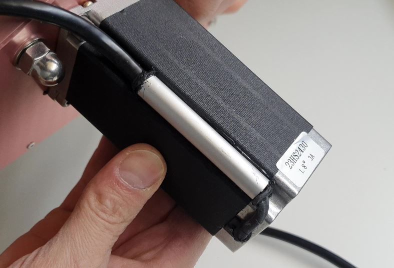
ii
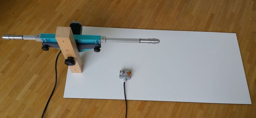
lm42p-diy, Release 1

On this page you will find all the information you need to build the LoveMachine42People. Five parts are dedicated
to detail all the operations of realization. You will find respectively the plans for the Machine, the Electrical Part, the
Fixing Components, the Accessories and the Wooden Storage Box.
This page is under construction, so it may not contain all the details yet. But come back from time to time to see the
progress.
This page takes me a lot of time to write, it would be a great support if you could make a small donation for its
realization by clicking on the PayPal logo below or by subscribing to my youtube channel. That way, I will be all the
more motivated to finish it quickly and it will allow me to know your interest in acquiring the plans of this machine.

Thank You a thousand times for your support!
The puplication of this document is only dedicated to the manufacture of your personal machine. You can read it for
educational purposes. Any use of this document for commercial purposes is strictly prohibited. The copy of all parts
referring to this product (photos, videos, plans) is prohibited and must be requested to the author LM42P.

Contents:                                                                                                                1
lm42p-diy, Release 1

2                      Contents:
CHAPTER   1

                         Machine

1.1 Moving Parts

1.1.1 Listing Parts

Motor

Quantity : 1x

                                3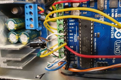
lm42p-diy, Release 1

Timing Pulley

    • Quantity : 1x
    • Type : HTD3M Type 40T
    • Size : hole diameter = 8mm width = 16mm
    • Where to buy :

Timing Belt

Quantity : 1x

Idler Pulley Long Screw

Quantity : 2x

Idler Pulley Short Screw

Quantity : 2x

4                                               Chapter 1. Machine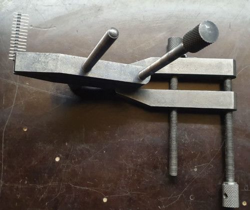
lm42p-diy, Release 1

Belt Joint

Quantity : 1x

Rod

Quantity : 1x or 2x

1.1. Moving Parts                       5
lm42p-diy, Release 1

1.1.2 Idler Pulley Long Screw

Listing Parts

    1) Long Screw M8
          • Quantity : 1x
          • Length : 50mm
          • Material : stainless

    2) Washer 8 x 12 x 1.5
          • Quantity : 4x
          • Material : aluminium

6                                  Chapter 1. Machine
lm42p-diy, Release 1
Note: Maybe better to use 1x Stainless steel Flat Washer Thickness 1mm (8x14x1mm) and 1x Stainless steel Flat
Washer 0.5mm (8x14x0.5). 1.5mm doesn’t exist. Because aluminum tends to crush when it’s squeezed.
3) Flange Ball Bearing
• Quantity : 2x
• Type : F698ZZ
• Size : 8 x 19 x 6 mm
4) Flat Washer
• Quantity : 2x
• Thickness : 0.5mm
• Size : 8 x 12 x 0.5 mm
• Material : stainless
1.1. Moving Parts 7lm42p-diy, Release 1
5) Bearing
• Quantity : 1x
• Type : 698ZZ
• Size : 8 x 19 x 6 mm
6) Washer M6
• Quantity : 1x
• Material : stainless
• Size : 8 x 16 x 1.6 mm
7) Nuts M8 Stop
• Quantity : 1x
• Material : stainless
8 Chapter 1. Machinelm42p-diy, Release 1
1.1.3 Idler Pulley Short Screw
Listing Parts
1) Short Screw M8
• Quantity : 1x
• Length : 35mm
• Material : stainless
2) Washer 8 x 12 x 1.5
• Quantity : 4x
• Material : aluminium
1.1. Moving Parts 9lm42p-diy, Release 1
Note: Maybe better to use 1x Stainless steel Flat Washer Thickness 1mm (8x14x1mm) and 1x Stainless steel Flat
Washer 0.5mm (8x14x0.5). Because aluminum tends to crush when it’s squeezed.
3) Flange Ball Bearing
• Quantity : 2x
• Type : F698ZZ
• Size : 8 x 19 x 6 mm
4) Flat Washer
• Quantity : 2x
• Thickness : 0.5mm
• Size : 8 x 12 x 0.5 mm
• Material : stainless
10 Chapter 1. Machinelm42p-diy, Release 1
5) Bearing
• Quantity : 1x
• Type : 698ZZ
• Size : 8 x 19 x 6 mm
6) Washer M6
• Quantity : 1x
• Material : stainless
• Size : 8 x 16 x 1.6 mm
7) Cap Nuts M8
• Quantity : 1x
• Material : stainless
1.1. Moving Parts 11lm42p-diy, Release 1
1.1.4 Belt Joint
Listing Parts
1. Base Belt Joint
• Quantity : 1x
• Material : 3D printed PLA (innerfill = 100%)
12 Chapter 1. Machinelm42p-diy, Release 1 2. Counterpart Base Belt Joint • Quantity : 1x • Material : 3D printed PLA (innerfill = 100%) 3. Spacer Metal Disc • Quantity : 1x • Material : Aluminium 4. Metal Disc • Quantity : 2x • Type : MSD-17 • Inner diameter 17 mm, as a counterpart to magnets, not a magnet! 1.1. Moving Parts 13
lm42p-diy, Release 1

     5. Phillips Head Screw M3 x 10
     • Quantity : 2x
     • Material : steel (should be magnetic)

     6. Washer M6 x 6.4 x 18 x 1.6
     • Quantity : 1x
     • Material : steel

     7. Screw Pan Head Slot M4 x 40
     • Quantity : 1x
     • Material : steel

14                                             Chapter 1. Machine
lm42p-diy, Release 1 1.2 Static Parts 1.2.1 Listing Parts Square Bushing Quantity : 2x 1.2. Static Parts 15
lm42p-diy, Release 1

1.2.2 Square Bushing

16                     Chapter 1. Machine
CHAPTER 2
Electrical Part
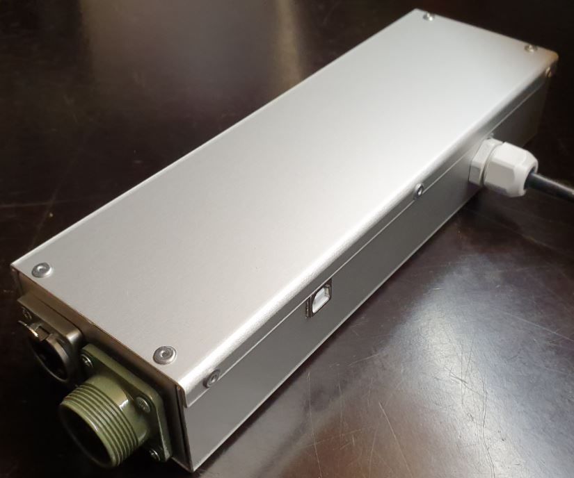
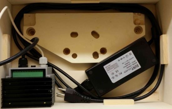
17lm42p-diy, Release 1 2.1 Electrical Box Note: There is another Electrical Box which is about 130$ cheaper but 15-20% slower and 40% less powerful (instead of 29 lbs thrust 17 lbs) The Box is 3D printed. Driver : 18 Chapter 2. Electrical Part
lm42p-diy, Release 1

Power 24V, 6A :

2.1.1 Listing Parts

U Base

   • Quantity : 1x
   • Material : anodized aluminium

2.1. Electrical Box                                   19
lm42p-diy, Release 1

U Top

     • Quantity : 1x
     • Material : anodized aluminium

U Right

     • Quantity : 1x

20                                     Chapter 2. Electrical Part
lm42p-diy, Release 1 • Material : anodized aluminium U Left • Quantity : 1x • Material : anodized aluminium Geckodrive G201X • Quantity : 1x 2.1. Electrical Box 21
lm42p-diy, Release 1
Arduino Uno
• Quantity : 1x
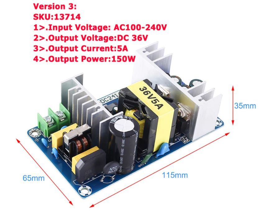
Power 36V
• Quantity : 1x
22 Chapter 2. Electrical Partlm42p-diy, Release 1 Power 36/12V • Quantity : 1x • Type : LM2596 Connector Socket 5 pins Female Insert • Quantity : 1x Plug RJ45 • Quantity : 1x • Include : 2x screw M3, 2x nuts M3 and 2x spring washer 2.1. Electrical Box 23
lm42p-diy, Release 1

Cable Gland

     • Quantity : 1x
     • Type : M16 4.5-10mm
     • Include : 1x nuts M16

Cable Ties

     • Quantity : 1x
     • Purpose : To be sur that the Cable Silicone 3 cores can’t be pull out

24                                                                             Chapter 2. Electrical Part
lm42p-diy, Release 1 Cable Silicone 3 Cores • Length : 1x 2m • Type : 0.75mm^2 • Note : I used silicone because it’s easy to fold. Plug 110 / 220 V Male PCB PIN Header • 1x 15 pins • 1x 10 pins • 1x 8 pins 2.1. Electrical Box 25
lm42p-diy, Release 1

Connector RJ45

     • Quantity : 1x
     • Length : 15cm

Ground Terminal M3

     • Quantity : 1x

Capacitor Polarized 1uF

     • Quantity : 1x
     • Purpose : This reduce the noise while reading the speed on the remote-control

26                                                                                     Chapter 2. Electrical Part
lm42p-diy, Release 1 Spacer 6-8-3mm • Quantity : 4x • Material : aluminium Square 10-12-9mm • Quantity : 2x • Material : aluminium • Purpose : Reinforcement of the fixaton (glue) of the Arduino Uno to the U Base 2.1. Electrical Box 27
lm42p-diy, Release 1

Countersunk Head Screw M3 x 8mm

     • Quantity : 4x
     • Material : Stainless Steel
     • Purpose : To fix Geckodrive on the U Base

Countersunk Head Screw M3 x 12mm

     • Quantity : 4x
     • Material : Stainless Steel
     • Purpose : To fix the Connector Socket 5 pins Female Insert on the U Right

28                                                                                 Chapter 2. Electrical Part
lm42p-diy, Release 1 Countersunk Head Screw M3 x 14mm • Quantity : 3x • Material : Stainless Steel • Purpose : To fix the Power 36V on the U Base Countersunk Head Screw M3 x 16mm • Quantity : 1x • Material : Stainless Steel • Purpose : To fix the Power 36V also the Ground Terminal on the U Base 2.1. Electrical Box 29
lm42p-diy, Release 1

Washer M3

     • Quantity : 12x

Nuts M3

     • Quantity : 12x

Rivet

     • Quantity : 14x
     • Type : diameter 3mm, length 6mm
     • Material : Stainless Steel

30                                       Chapter 2. Electrical Part
lm42p-diy, Release 1 Glue Silicone • Quantity : 1x • Type : Polyflex 444 • Purpose : To glue the Arduino Uno to the U Base using the Square 10-12-9mm to fix stronger Threadlocker Glue • Quantity : 1x • Type : Loctite 243 • Purpose : To glue the Nuts M3 2.1.2 Operation Plan 2.1. Electrical Box 31
lm42p-diy, Release 1

Make The Sheets Parts

Make the U Base, U Right and the U Left following this Video, see also the drawings below :
Drawings :
Material : aluminium

                                                 Fig. 1: U Base

Make the Spacer 6-8-3mm

See the following video :

32                                                                                 Chapter 2. Electrical Part
lm42p-diy, Release 1
Fig. 2: U Top
Fig. 3: U Right
2.1. Electrical Box 33lm42p-diy, Release 1
Fig. 4: U Left
34 Chapter 2. Electrical Partlm42p-diy, Release 1
Drawing :
• Quantity : 4x
• Material : aluminium
Fig. 5: Spacer 6-8-3mm
Make the Square 10-12-9mm
See the following video :
Drawing :
• Quantity : 2x
• Material : aluminium
Fig. 6: Square 10-12-9mm
2.1. Electrical Box 35lm42p-diy, Release 1
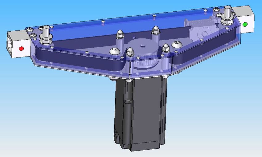
Scrape the surface on the U Base
File the bottom of the U Base (only the part where the red framed hole is) so that the grounding contact faces well.
This operation is not necessary if you are using non anodized sheets.
Note: The anodized surfaces are not conductive.
See Video :
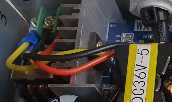
Control Power 36V
Control the voltage of the output of the Power 36V with a voltmeter. It should be 36V.
Adjust voltage Power 36/12V
Materials:
• 1 wire 0.5mm^2 red length = 120mm
• 1 wire 0.5mm^2 red length = 150mm
• 1 wire 0.5mm^2 black length = 140mm
• 1 wire 0.5mm^2 black length = 60mm
1) Sold the wire
36 Chapter 2. Electrical Partlm42p-diy, Release 1
2) Wire the Power 36/12V
• Connect the Power 36/12V IN to the Power 36V OUT
• Connect the voltmeter to Power 36/12V OUT
3) Adjust the voltage
With a Screwdriver 0, adjust the voltage to 12V
Fix the Power Cable to the Electrical Box
See Video :
1. Strip the Cable Silicone 3 Cores at 10cm
2. Fix the Cable Gland to the U Base
3. Tighten Cable Gland
4. Tighten the Cable Ties and cut it with a Cutting Pliers
5. Tighten the Ground Terminal M3 on the ground wire (yellow)
6. Tighten the Phase and Neutre to Power 36V “IN”
2.1. Electrical Box 37lm42p-diy, Release 1
Set Geckodrive current limit
• For G203V :
Connect a resistor of 120kOhms between pin 11 and 12 of the GECKODRIVE. This will limit MOTOR current
by 5A.
• For G201X :
set the switches like the following figure
Screw the Power 36V and Geckodrive on the U Base
Note: Use Threadlocker Glue.
• For Power 36V :
1. Fix three corners of the Power 36V by using :
– 3x Spacer 6-8-3mm
– 3x Countersunk Head Screw M3 x 14mm
– 3x Washer M3
– 3x Nuts M3
2. Fix the last corner [The ground to the U Base by using :]
– 1x Countersunk Head Screw M3 x 16mm
– 1x Washer M3
– 1x Nuts M3
38 Chapter 2. Electrical Partlm42p-diy, Release 1
– 1x Ground Terminal M3 (the ground on the Cable Silicone 3 Cores
Power 36V U Base
GROUND screw with Spacer
• For Geckodrive use :
– 4x Head Screw M3 x 8mm
– 4x Washer M3
– 4x Nuts M3
Glue the Power 36/12V and Arduino Uno
Glue the Arduino Uno at the U Base with Glue Silicone and Square 10-12-9mm and the Power 36/12V.
2.1. Electrical Box 39lm42p-diy, Release 1 40 Chapter 2. Electrical Part
lm42p-diy, Release 1

Wiring

See video :
   1. Sold the wires to the Male PCB PIN Header (15, 10, 8 pins), except the POWER 36/12V OUT+
      Use two clamps this help to sold the Male PCB PIN Header

                               GECKODRIVE        ARDUINO         Cable Length
                               8 (DIR)           PIN 8           11cm
                               9 (STEP)          PIN 9           11cm
                               10 (COMMON)       GND             7cm

2.1. Electrical Box                                                                                  41
lm42p-diy, Release 1
Fig. 7: Male PCB PIN Header 15 pins
Fig. 8: Male PCB PIN Header 10 and 8 pins
42 Chapter 2. Electrical Partlm42p-diy, Release 1
POWER 36/12V ARDUINO Cable Length
OUT- GND 6cm
OUT+ VIN 12cm
ARDUINO RJ45 cable (inside Box) Cable Length
A0 6 sold capacitor + 12cm
A1 5 “
A2 4 “
A3 3 “
~3 2 15cm
~5 1 “
GND 8 sold capacitor - 12cm
+5V 7 “
2. Sold the Capacitor between A0 and GND (8) see folowing picture
3. Connect :
Power 36V GECKODRIVE Cable Length
-DC 1 (POWER GND) 6cm
D+ 2 (18 TO 80 VDC) “
2.1. Electrical Box 43lm42p-diy, Release 1
Power 36V POWER 36/12V Cable Length
-DC IN- 14cm
DC+ IN+ 15cm
GECKODRIVE Female Connector (MOTOR) Cable Length
3 (WINDING A) A 15cm
4 (WINDING not A) B “
5 (WINDING B) C “
6 (WINDING not B) D “
Upload the programm to Arduino Uno and final control
1. Plug the PC using an USB cable to the Electrical-Box
2. Upload the programm (soon available)
3. Control if every thing is ok (the *Machine, Remote Control, Stepper Motor and the Rod should be done). Do
all these steps showed in that video for the test :
4. Cover with U Top and Rivet
2.2 Remote Control
2.2.1 Listing Parts
Box
• Quantity : 1x
• 3D Printed in PLA
44 Chapter 2. Electrical Partlm42p-diy, Release 1 Cover • Quantity : 1x • 3D Printed in PLA Potentiometer • Quantity : 2x • Type : 10k 2.2. Remote Control 45
lm42p-diy, Release 1

Potentiommeter Knobs

     • Quantity : 1x Grey (stroke), 1x Gold (speed)

RJ45 Cable

     • Quantity : 1x
     • Length : 2.5m
     • Type : Ultrafine

Cable Gland M12

     • Quantity : 1x

46                                                    Chapter 2. Electrical Part
lm42p-diy, Release 1 • Type : M12 3-6mm Epoxy • Resin and Hardener Pigment Epoxy • Quantity : 1x color black, 1x color red, 1x color green 2.2. Remote Control 47
lm42p-diy, Release 1

Cable Ties

      • Quantity : 1x
      • Purpose : To be sur that the RJ45 Cable can’t be pull out

Screw

      • Quantity : 4x
      • Diameter : 2.9mm
      • Length : 13mm
      • Stainless steel

2.2.2 Operation Plan

See the video :

Make the Box

Print it in PLA. Infill = 50% File : soon available. . .

Make the Cover

     1. Print it in PLA. Infill = 50% File : soon available. . .
     2. Prepare the Epoxy with black pigment, red pigment and green pigment
     3. Fill with pigmented Epoxy the inscriptions on the Cover

48                                                                            Chapter 2. Electrical Part
lm42p-diy, Release 1 4. Cure the Epoxy then sand it very thin (60, 240, 400) 5. Place the Potentiometer (2x) and and tighten them Wiring the Remote Control 2.2. Remote Control 49
lm42p-diy, Release 1

                                         Remote-Control     RJ45 cable
                                         A0                 6
                                         A1                 5
                                         GND                8
                                         +5V                7

     1. Strip the RJ45 Cable at 7cm
     2. Cut the unused wire
     3. Use the cutted unused wire to make the bridge between GRD and +5V inside the Remote Control

2.3 Motor

This section shows how to fix the Cable Silicone 4 Cores to the Connector Plug 5 pins Male Insert and the Motor

2.3.1 Listing Parts

Motor

     • Quantity : 1x
     • Type : Stepper Motor NEMA 23 23HS11240
     • Length : 112mm
     • 4.2A

50                                                                                 Chapter 2. Electrical Part
lm42p-diy, Release 1 Connector Plug 5 pins Male Insert • Quantity : 1x Cable Silicone 4 Cores • Quantity : 2.2m • 0.75 mm^2 2.3. Motor 51
lm42p-diy, Release 1

Tube Cable Holder

     • Quantity : 1x
     • Material : Aluminium

Heat Shrink Tube

     • Quantity : 4x - Length : 13mm
     • Quantity : 1x - Length : 37mm

Screw Hex Head Allen M5 x 40

If the Motor isn’t fixed yet on the Machine, then 1x Screw is needed.
     • Quantity : 1x
     • Size : M5 x 40

52                                                                      Chapter 2. Electrical Part
lm42p-diy, Release 1 • Type : Stainless Allen Bolt Socket Cap Screw Hex Head Allen Key DIN912 Glue Silicone • Quantity : 1x • Type : Polyflex 444 Cable Ties • Quantity : 1x 2.3. Motor 53
lm42p-diy, Release 1

2.3.2 Connect the Connector Plug 5 pins Male Insert

Operation Plan

See the video :
Wiring
     1. strip the cable at 3cm
     2. strip the 4 wires and solder the wires
     3. 5cm from the edge roll up the 10-layers adhesive tape
     4. pass the cable and solder the wires in the plug in counter-clockwise order
           • black (A)
           • yellow (B)
           • red (C)
           • green (D)

54                                                                                   Chapter 2. Electrical Part
lm42p-diy, Release 1
5. assemble the plug and tighten the flange
2.3.3 Connect and fix the Cable Silicone 4 Cores to the Motor
Operation Plan
See the video :
1. Make the Tube Cable Holder
Fig. 9: Tube Cable Holder (material aluminium anodized)
2. Unpacking and motor control. Plug the 4 wires on an Electrical Box and make it turn. This is important before
making the following steps.
3. Cut the Cable Silicone 4 Cores at 2.2m
4. Cut the red wire at 47mm; cut the yellow at 57mm; cut the blue wire at 67mm; cut the green wire at 77mm see
following picture
2.3. Motor 55lm42p-diy, Release 1
5. Stripping, twisting, tinning the motor wires to 5mm
6. Cut the Heat Shrink Tube to 37mm length and tighten it with industrial foehn. The red wire should protrude
about 5mm..
7. Strip the Cable Silicone 4 Cores to 45mm.
8. Cut the red wire on the Cable Silicone 4 Cores at 40mm; the yellow wire at 30mm; the black wire at 20mm;
the green wire at 10mm.
9. Strip, twist, tin-plate the cable wires to 5mm.
10. Cut 4x Heat Shrink Tube at 13mm
11. Put 13mm Heat Shrink Tube + Tube Cable Holder (pay attention to direction the chamfer 1x45) and solden
12. Degrease Tube Cable Holder, Cable Silicone 4 Cores and Motor with acetone
Warning: If the Motor isn’t fixed on the machine yet, then don’t forget to put the screw in the motor hole
(see picture below)
13. Inject the Glue Silicone through the 4mm hole diam. until it comes out of both sides of the Tube Cable Holder;
take the surplus and apply it to the Motor on the groove where the Screw Hex Head Allen M5 x 40 has been
placed; turn the Tube Cable Holder so that the injection hole is against the Motor and is not visible; put a
Cable Ties on the Cable Silicone 4 Cores , put the Tube Cable Holder on with the clamp see following picture
56 Chapter 2. Electrical Partlm42p-diy, Release 1
if necessary, inject at the end of the Tube Cable Holder where the chamfer is located and put some Glue
Silicone on the Motor if you see the wires that protrude a little beyond the Heat Shrink Tube
14. Allow to harden; clean and remove the beads on Tube Cable Holder.
2.3. Motor 57lm42p-diy, Release 1 58 Chapter 2. Electrical Part
CHAPTER           3

                                                                                                Accessories

3.1 Rod

3.1.1 Listing Parts

  1) Magnet
      Pot magnet with threaded stud diam. 16mm Thread M4 strength approx. 8kg
         • Quantity : 1x
         • Type : GTN-16
         • Where to buy :

Note: It’s important to buy at supermagnete because I bought some in Aliexpress but the strength is lower than those

                                                                                                                 59
lm42p-diy, Release 1
bought at supermagnete
3.2 Vac u Lock Adapter
3.2.1 Silicon Mold
Listing Parts
1) Cup
2) Centerign Cover
3) Threaded Stem
4) Aluminium Vac u Lock Model
Operation Plan
1) Prepare 220g silicon and 11g hardener
2) Stir 5min
60 Chapter 3. Accessorieslm42p-diy, Release 1 3) Put a tape border on the plastic cup 4) Wait 20min to remove the bubles 5) Fill in through one of the hole 3.2.2 Mold the Adapter 1) Use a 50mm long M6 bolt 2) Prepare 20g cast and 20g hardener 3) Stir really slowly 3.2. Vac u Lock Adapter 61
lm42p-diy, Release 1

62                     Chapter 3. Accessories
CHAPTER 4
Fastening Elements
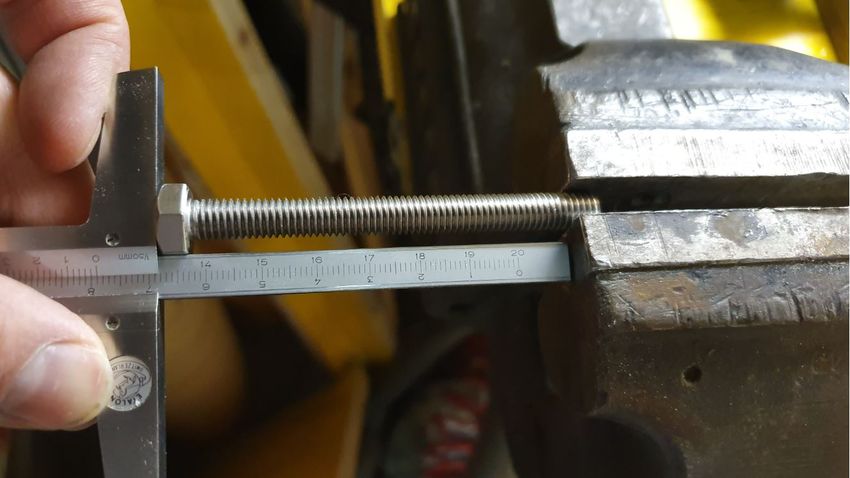
4.1 Fastening bolt
1. Saw the bolt
63lm42p-diy, Release 1
2. Deburr the bolt
4.2 Silicone-Plate 60x40x3
1. Cut the plate with a cutter
2. Cut wiht a cookie cutter the hole diameter 6mm
4.3 Allen Cone Head Screw
• Type : M8 x 45mm
• Supplier : Debrunner
• N° Article : 101 14 091
64 Chapter 4. Fastening Elementslm42p-diy, Release 1 4.4 Allen Tightening Key • Type : 5mm • Supplier : Debrunner • N° Article : 811 305 240 4.4. Allen Tightening Key 65
lm42p-diy, Release 1

66                     Chapter 4. Fastening Elements
CHAPTER           5

                                                                                                             Code

Here is the Arduino code. You can download it from here : . I’m not a professional programmer. The code is a bit
messy sorry about that. At the begining I tried to use AccelStepper library for Arduino but couldn’t get it work well.
(couldn’t reach an appropriate speeed I don’t know why) so I remove AccelStepper library and tried to do something
and it worked not badly. Sorry the comments in the code are in french, I’ll translate them soon!
Maybe this video can help to understand the code
// CodeGeckoV4.ino
// Elimine le full stroke quand on débranche la Télécommande en pleine action. V3 ->
 ˓→V4

// Comme le fait de lire la vitesse du potentiomètre prend relativement beaucoup de
 ˓→temps, cela réduit la vitesse de pulsation

// de la pin 9. Pour parer à ceci le programme a été adapté pour lire la vitesse tous
 ˓→les 300 itérations à basse vitesse

// et lorsque la vitesse du potentiomètre dépasse les 100 alors des boucles d
 ˓→'accélértions et de décélération sont

// requise pour ne pas faire décrocher le moteur lors des inversions de sens de
 ˓→rotations. (avec ceci, il est possible

// de diminué le délais entre pulse et ainsi la vitesse est augmentée) Comme la
 ˓→vitesse est rapide

// la vitesse est alors lue après un cycle complet de va-et-vient. Pour simplifier,
 ˓→la course n'est lue qu'après un

// cycle complet de va-et-vient. Un autre point important est de lire la vitesse
 ˓→souvent à basse vitesse :

// par exemple si la vitesse est au mini et la course est grande, alors cela prendra
 ˓→une éternité pour que le

// va-et-vient se termine jusqu'à la prochaine lecture de vitesse.
// L'accélération et la décélération est linéaire (après un cycle de pulse, le délais
 ˓→est soustrait ou additioné de 1).

#define step_pin 9           // Pin 9 connected to Steps pin on ST-M5045 ou ... c'est
 ˓→la pin du pulse (un pulse c'est un pas en mode full

                             // ou en mode 1600pas/rev : 8 pulses pour un pas avec un
 ˓→motor de 1.8deg ou 200pas/rev)                                        (continues on next page)

                                                                                                                   67
lm42p-diy, Release 1
(continued from previous page)
#define dir_pin 8 // Pin 8 connected to Direction pin
#define home_switch 12 // Pin 12 connected to Home Switch (MicroSwitch)
#define ref 0 // c'est le 0 ici l'inversion est faite en mode basse
˓→vitesse (sans accélération ni décélération)
//
˓→***************************************************************************************************
//**********************PARAMETRES
˓→MODIFIABLES****************************************************************************************
#define v_max 40 // C'est la vitesse maximale lue par le potentiomètre de
˓→vitesse (délai en microseconde entre deux pulses) 30 50 45 55 65 70 65 original 50
#define v_min 1200 // C'est la vitesse minimum lue par le potentiomètre de
˓→vitesse (délai en microseconde entre deux pulses)
#define v_max_inv 200 // C'est la vitesse maximale à laquelle le moteur ne
˓→décroche pas 200 280 original 200
// à l'inversion de sens de rotation en 1600pas/rev. En
˓→dessous de cette vitesse,
// l'accélération et la décélération ne sont pas requise.
#define course_max 2968 // C'est la course maximale lue par le potentiomètre de
˓→course 2150 2125 2100 2080 origine 2320 2500
// pour l'accélération et la décélération. Soit course_
˓→ min > 2*(v_max_inv - v_max) = distance max de freinage ou d'accélération avant 420
#define marge 30 // C'est la marge que l'on ajoute au moment ou le fin-de-
˓→course est relaché pour que la référence 0 soit
// soit plus loin avant 30 originale = 50
//
˓→***************************************************************************************************
int course_min = 380; // C'est la course minimum lue par le potentiomètre de
˓→course. Attention de bien respecter le minimum de course à haute vitesse. 380
// Si on est dans le mode basse vitesse alors on peut
˓→réduire la course ainsi pour faire un vibro.
int diff_course = 1200; // C'est la tolérance d'une différence de course évite
˓→que la course se met au max quand il y a du bruit
int x=v_max_inv; // Variable de délai entre impulsion qui varie selon
˓→accéleration et décélération
int steps=0; // Variable compteur de pas. Sert à savoir la position du
˓→bras
int steps_init=0; // Variable compteur de pas. Pour la prise de référence à l
˓→'initialisation
int analog_read_counter = 300; // Permet de pas lire trop souvent la vitesse du
˓→potentiometre
int customCourseMapped; // Pour stocker la consigne de la course courante
int customCourseMapped_pre; // Pour stocker la consigne de la course précédente (pour
˓→controler que la diff n'est pas trop grande (sécurité)
int customSpeedMapped; // Pour stocker la consigne de la vitesse
int dist_frein = v_max_inv-v_max; // C'est la vitesse de freinage. On initialise à la
˓→valeur max (quand la vitesse est la plus grande)
bool CoteVert = false;
bool CoteRouge = false;
bool CoteMilieu = false;
void setup() { pinMode(dir_pin, OUTPUT);
pinMode(step_pin, OUTPUT);
(continues on next page)
68 Chapter 5. Codelm42p-diy, Release 1
(continued from previous page)
digitalWrite(dir_pin, LOW);
digitalWrite(step_pin, LOW);
//Serial.begin(9600);
pinMode(home_switch, INPUT_PULLUP);
delay(1000); // on attend un peu
// Start Homing procedure of Stepper Motor at startup
/* while (!(course_max + 150 == steps_init)) { // Tant que la toute la course + un
˓→chouillla n'est pas accomplie, on va vers la butée
digitalWrite(dir_pin, HIGH);
digitalWrite(step_pin, LOW);
delay(1);
digitalWrite(step_pin, HIGH);
delay(1);
steps_init=steps_init+1;
}*/
steps=-marge; // lorsque le fin-de-course est relaché, on rajoute un poil de cul
˓→ plié en quatre pour que le 0 soit un peu plus loin
if(speedUp() > 1100 && course() < 400){
CoteVert = true;
CoteRouge = false;}
if(speedUp() < 100 && course() > 2600){
CoteRouge = true;
CoteVert = false;}
if((speedUp() > 400 && speedUp() < 800) && (course() > 1290 && course() < 2090)){
CoteMilieu = true;
CoteVert = false;
CoteRouge = false;}
if(CoteMilieu){
while(stepslm42p-diy, Release 1
(continued from previous page)
while(1){} // On rentre en boucle infinie (pour la sécurité évite de se faire
˓→percer trop violemment)
}
while ((customSpeedMapped) > (v_min - 17)){ // si le potentiomètre de la vitesse
˓→est au minimum, on met LM42P à l'arrêt
// int a=1;
//customSpeedMapped =speedUp(); // lecture de la vitesse
if (analog_read_counter > 0) {
analog_read_counter--;
}
else {
analog_read_counter = 400;
customSpeedMapped =speedUp(); // permets de modifier la vitesse sans devoir
˓→attendre un va complet
}
}
if(CoteVert){
if(customSpeedMapped200) { // Mode basse vitesse. Ici l'accélération et la
˓→décélération ne sont pas requise.
while(steps 0) {
analog_read_counter--;
}
else {
analog_read_counter = 300;
customSpeedMapped =speedUp(); // permets de modifier la vitesse sans devoir
˓→attendre un va complet
}
(continues on next page)
70 Chapter 5. Codelm42p-diy, Release 1
(continued from previous page)
}
//*
digitalWrite(dir_pin, HIGH); //changement de direction et va jusqu'à la référence 0
while(steps>ref){
digitalWrite(step_pin, HIGH);
delayMicroseconds(customSpeedMapped);
digitalWrite(step_pin, LOW);
delayMicroseconds(customSpeedMapped);
steps--;
//Serial.println(steps);
// We only want to read the pot every so often (because it takes a long time we
˓→don't
// want to do it every time through the main loop).
if (analog_read_counter > 0) {
analog_read_counter--;
}
else {
analog_read_counter = 300;
customSpeedMapped =speedUp(); // permets de modifier la vitesse sans devoir
˓→attendre un va complet
}
}
}
else{
// ici la vitesse rapide est activée et l'accélération et la décélértion est
˓→ requise
digitalWrite(dir_pin, LOW);
//accélération et va jusqu'à course
while(stepscustomSpeedMapped) x--; // tant que x est plus grand (plus x est grand plus
˓→la vitesse est lente) que la vitesse du poto, on accélère
steps++;
}
// Là on a atteint la course - la distance de freinage
//décélération
while (xlm42p-diy, Release 1
(continued from previous page)
digitalWrite(step_pin, HIGH);
delayMicroseconds(x);
digitalWrite(step_pin, LOW);
delayMicroseconds(x);
//Serial.println(steps);
if(x>customSpeedMapped) x--;
steps--;
}
while(xlm42p-diy, Release 1
(continued from previous page)
else {
analog_read_counter = 300;
customSpeedMapped =speedUp(); // permets de modifier la vitesse sans devoir
˓→attendre un va complet
}
}
//*
digitalWrite(dir_pin, LOW); //changement de direction et va jusqu'à la référence 0
while(steps>ref){
digitalWrite(step_pin, HIGH);
delayMicroseconds(customSpeedMapped);
digitalWrite(step_pin, LOW);
delayMicroseconds(customSpeedMapped);
steps--;
//Serial.println(steps);
// We only want to read the pot every so often (because it takes a long time we
˓→don't
// want to do it every time through the main loop).
if (analog_read_counter > 0) {
analog_read_counter--;
}
else {
analog_read_counter = 300;
customSpeedMapped =speedUp(); // permets de modifier la vitesse sans devoir
˓→attendre un va complet
}
}
}
else{
// ici la vitesse rapide activée et l'accélération et la décélértion est requise
digitalWrite(dir_pin, HIGH);
//accélération et va jusqu'à course
while(stepscustomSpeedMapped) x--; // tant que x est plus grand (plus x est grand plus
˓→la vitesse est lente) que la vitesse du poto, on accélère
steps++;
}
// Là on a atteint la course - la distance de freinage
//décélération
while (xlm42p-diy, Release 1
(continued from previous page)
}
digitalWrite(dir_pin, LOW); //Changement de direction
while(steps>(ref+dist_frein)){ // Acccélération et va jusqu'à la référence +
˓→distance de freinage.
digitalWrite(step_pin, HIGH);
delayMicroseconds(x);
digitalWrite(step_pin, LOW);
delayMicroseconds(x);
//Serial.println(steps);
if(x>customSpeedMapped) x--;
steps--;
}
while(xlm42p-diy, Release 1
(continued from previous page)
// want to do it every time through the main loop).
if (analog_read_counter > 0) {
analog_read_counter--;
}
else {
analog_read_counter = 300;
customSpeedMapped =speedUp(); // permets de modifier la vitesse sans devoir
˓→attendre un va complet
}
}
//*
digitalWrite(dir_pin, HIGH); //changement de direction et va jusqu'à la référence 0
while(steps>((course_max/2)-(customCourseMapped/2))){
digitalWrite(step_pin, HIGH);
delayMicroseconds(customSpeedMapped);
digitalWrite(step_pin, LOW);
delayMicroseconds(customSpeedMapped);
steps--;
//Serial.println(steps);
// We only want to read the pot every so often (because it takes a long time we
˓→don't
// want to do it every time through the main loop).
if (analog_read_counter > 0) {
analog_read_counter--;
}
else {
analog_read_counter = 300;
customSpeedMapped =speedUp(); // permets de modifier la vitesse sans devoir
˓→attendre un va complet
}
}
}
else{
// ici la vitesse rapide activée et l'accélération et la décélértion est requise
digitalWrite(dir_pin, LOW);
//accélération et va jusqu'à course
while(stepslm42p-diy, Release 1
(continued from previous page)
digitalWrite(step_pin, LOW);
delayMicroseconds(x);
//Serial.println(steps);
if(x((course_max/2)-(customCourseMapped/2)+dist_frein)){ // Acccélération
˓→et va jusqu'à la référence + distance de freinage. steps>((course_max/2)-
˓→(customCourseMapped/2))
digitalWrite(step_pin, HIGH);
delayMicroseconds(x);
digitalWrite(step_pin, LOW);
delayMicroseconds(x);
//Serial.println(steps);
if(x>customSpeedMapped) x--;
steps--;
}
while(xCHAPTER 6
Donate
Please give me a small tip to help me continue this self-buiding site! Click the following Paypal.me Icon or subscribe
to my Youtube Channel.
Thank You very much!
77lm42p-diy, Release 1 78 Chapter 6. Donate
CHAPTER   7

                                         Contact

Address :
      LM42P
      1010 Lausanne Switzerland
internet :
      https://lm42p.com
email :
      lovemachine42people@gmail.com

                                                79
lm42p-diy, Release 1 80 Chapter 7. Contact
CHAPTER    8

             Indices and tables

• genindex
• modindex
• search

                             81
You can also read