Can't We All Get Along? Importing AutoCAD Electrical Data to Autodesk Inventor Cable and Harness
←
→
Page content transcription
If your browser does not render page correctly, please read the page content below
Can’t We All Get Along?
Importing AutoCAD® Electrical Data to
Autodesk® Inventor® Cable and Harness
Mark Allen Flayler : ASCENT – Center for Technical Knowledge®

ML215-2            Bring the electrical and mechanical engineers together with AutoCAD Electrical and
Autodesk Inventor Professional. Learn how to import the controls design data from AutoCAD Electrical into
the Inventor Professional Cable and Harness environment. Learn how to configure the Inventor wire library
and publish connectors in Inventor to support the AutoCAD Electrical data. Publish DWF files from AutoCAD
Electrical and Inventor, and then top it off by combining the DWF files in Design Review to share outside the
engineering department. This class is targeted at Inventor users interested in the interoperability potential of
Inventor Professional.

About the Speaker:
Mark is an Application Engineer with the ASCENT and IMAGINiT Division of RAND Worldwide, specializing
in the Autodesk manufacturing products. He has implemented the Autodesk Manufacturing products with
many industries including the blow and injection molding, automotive, and custom machinery markets.
Inventor has been a profound augmentation in his abilities allowing him to bring 3D digital prototyping to the
forefront of the industries with which he has interacted. He has extensive experience and a comprehensive
understanding of the technical, practical, business, and human dimensions of implementation. He is an
effective and skillful communicator, consulting with his clients to help achieve their business objectives. Mark
is an ATC certified instructor and has been instrumental in the training of hundreds of users. Mark is certified
in AutoCAD, AutoCAD Mechanical, AutoCAD Electrical, Autodesk Data Management, and Autodesk
Inventor.

Email: mflayler@rand.com
BLOG site: www.rand.com/imaginit/manufacturingBlog
Can’t We All Get Along? Importing AutoCAD® Electrical Data to Autodesk® Inventor® Cable and Harness

Introduction
The increasing need to digitally prototype designs for lean manufacturing has become a popular trend for
first class manufacturers. In recent releases, Autodesk has added the ability to share information back
and forth between its control design and 3D parametric software packages. This added functionality for
users to document their designs for installation, repair, and purchasing, as well as a host of other needs,
is a major advantage to the digital prototyping toolbox.

AutoCAD Electrical 2009 Overview

           AutoCAD Electrical software is purpose-built to create and modify electrical controls systems.
           AutoCAD Electrical delivers the tools needed to design electrical controls faster and more
           accurately than ever before.

Autodesk Inventor 2009 Overview

            Autodesk Inventor software provides a comprehensive and integrated set of tools for
            generating 3D mechanical design, including dynamic simulation, stress analysis, and design
            visualization. Cable and Harness exists in both Professional and Routed Systems versions.

Autodesk Design Review 2009 Overview

            Autodesk Design Review software is the free, all-digital way to share, review, mark up, and
            track changes to digital prototypes, all without access to the original creation software.

AutoCAD Electrical & Autodesk Inventor Interoperability

                           +                        +                        =                  _

                                 +                                    =
                                                                                                              3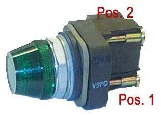
Can’t We All Get Along? Importing AutoCAD® Electrical Data to Autodesk® Inventor® Cable and Harness

Configuring AutoCAD Electrical
AutoCAD Electrical must be set up for the export to Inventor. To do this, simply ensure that the following
items are defined in the design and the conventional CAD standards:

 •     You must define wires in AutoCAD Electrical as valid wire layers. Click                     to access
       the Create/Edit Wire Type dialog box, as shown below.

 •     Set unique wire IDs. Navigate to the Project Properties for your wire numbers and toggle on the On
       per Wire Basis option, as shown below. This prevents duplicates when imported into Inventor.

                                                                                                             4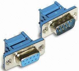
Can’t We All Get Along? Importing AutoCAD® Electrical Data to Autodesk® Inventor® Cable and Harness

•   Fix your wire numbers (recommended) so that subsequent imports into Inventor do not dramatically
    change the design in Cable and Harness. You can change your normal wire number to fixed with the
                       or                       command. An example is shown below.

•   When using the                 command, make sure you place the children, not just the parent. The
    figure below shows a Cable with fan in/out signals and individual Cable markers with their children on
    their respective wire layers.

•   Use the                                      command to export your data in XML format to Inventor.
    This command opens the dialog box shown below, and enables you to export the active drawing
    (Active drawing) or choose multiple files from which to extract information (Project). You can access
    this command under Projects > Reports or from the Schematic Reports flyout on the ACE: Electrical
    Main 2 toolbar. The XML file will export component, splice, wire, and cable information about the
    design.

                                                                                                        5
Can’t We All Get Along? Importing AutoCAD® Electrical Data to Autodesk® Inventor® Cable and Harness

Configuring Autodesk Inventor
Autodesk Inventor also needs to be set up for the import from Electrical. You can control this import by
defining commands “on the fly”, as needed, as well as having a predefined library in place.

 •       Inside an assembly, start the                 command and create your harness subassembly.
         Create and place your segments and electrical parts using conventional assembly modeling and part
         placement methodologies.

 •       The                         command can be configured so most error conditions do not appear. Most
         companies use a certain set of components that almost always meet their needs. Setting this up once
         and sharing it can save time and hassle. The Cable & Harness Library dialog box is shown below.

 •       The library can be configured for cables, labels, looms, plug, raw ribbon cables, seals, splices,
         terminals, wires, and other miscellaneous categories. You will focus on what Electrical brings over:
         cables, wires, and splices. You can configure the following parameters in the library:

 Option     Description

 Cables     Name, Category, Part Number, Outer Diameter, Bend Radius, Conductor Ids and their wire information, and optional
            custom properties.
 Wires      Name, Category, Part Number, Color Style, Outer Diameter, Gauge, custom properties and optionally the Core
            Diameter and Bend Radius.
 Splices    Name, Category, Part Number, # of Pins, Embedded Length, Gauge and Core Size (can be ranged, none, or fixed).

                                                                                                                               6
Can’t We All Get Along? Importing AutoCAD® Electrical Data to Autodesk® Inventor® Cable and Harness

•   You can manually make modifications in the dialog box or automate them with an import/export option.
    You need two files for the import/export of library information: CFG file and CSV data file

    1. A configuration file (CFG) that describes the format of a CSV file. The file contains input
       parameters, their data types, and corresponding units. It is created as a space- or tab-delimited
       text file. This can be created or edited with the       command, Excel, or more commonly,
       Notepad. Examples are shown below.

     Wire CFG File Example:                                 Splices CFG File Example:
     libwires                                               libsplices
     C:\libwires.log                                        C:\libcables.log
     Wire Name,Color Style,Outer Diameter, Category,Gauge   Library Name,Category,Part Number,Embedded Length,MyCustom
     text,text,length,text,text                             text,text,text,length,text
     none,none,inch,none,none                               none,none,none,inch,none

                           Cables CFG File Example:
                           Iibcables
                           C:\libcables.log
                           Cable Name,Category,Part Number,Outer Diameter,Conductor ID,Wire Name
                           text,text,text,length,text,text
                           none,none,none,inch,none,none

    2. A CSV data file that maps the import/export library values based on the CFG file. Certain library
       objects require different mapping (example, cables require multiple lines for multiple conductors).

     Wire CSV file                                          Cable CSV file

•   Use the               (Import and Export Library Objects) commands to merge or modify your library. In
    addition, make sure everyone on your team is using the same IWL file (Cable and Harness Library).
    This is stored with your Design Data folder. The Import Library Cables dialog box is shown below.

                                                                                                              7
Can’t We All Get Along? Importing AutoCAD® Electrical Data to Autodesk® Inventor® Cable and Harness
• Use the command to import data from XML Electrical into the current harness.
With this command, the exported XML file from Electrical imports component, splice, wire, and cable
information about the design. You will also look at the error codes as well for when items do not exist
in the Cable and Harness Library.
Electric Parts
Use to display component tags
and assigned pin numbers from the imported
XML. Right-click on an item to access the
following options:
Option Description
States any error condition and
Issue Description
how to fix it.
Assign to an existing Assigns the imported component
Electrical Part or and its occurrence information in
Choose from existing the of the
Electrical Parts selected part.
Rename Pin on Appears if the part already exists
Electrical Part and the pins do not match.
Splices
Use to display component tags and
assigned pin numbers from the imported XML.
Right-click on an item to access the following
options:
Option Description
States any error condition and
Issue Description
how to fix it.
Assigns the imported component
Assign to an existing and its occurrence information in
Splice or Choose from
existing Splice the of the
selected part.
8Can’t We All Get Along? Importing AutoCAD® Electrical Data to Autodesk® Inventor® Cable and Harness
Wires
Use to display wire numbers and
assigned pin numbers from the imported XML.
Right-click on an item to access the following
options:
Option Description
States any error condition and
Issue Description
how to fix it.
Create a new user wire
definition in the library, or
Add to Cable & Harness assigns a predefined wire in the
Library or Choose from library to the imported wire and
Cable & Harness Library occurrence information in the
.
Activates an edit field at the
Rename Imported Wire
wire’s browser node for
ID
renaming.
Cables
Use to display cable markers, their
children, and assigned pin numbers from the
imported XML. Right-click on an item to access
the following options:
Option Description
States any error condition and
Issue Description
how to fix it.
Create a new user cable
definition in the library, or
Add to Cable & Harness assigns a predefined cable in
Library or Choose from the library to the imported cable
Cable & Harness Library and occurrence information in
the .
Activates an edit field at the
Rename Imported Cable
cable’s browser node for
ID
renaming.
Opens the Select Conductor
Choose Conductor from dialog box so you can select a
Imported Cable different conductor for the wire
ID.
Rename Imported Cable Activate an edit field at the wire’s
Wire browser node for renaming.
9Can’t We All Get Along? Importing AutoCAD® Electrical Data to Autodesk® Inventor® Cable and Harness
Creating Electrical Parts
Q. What is the difference between the two parts shown below?
A. One is an electrical part; the other is a normal Inventor part.
The Pins, Harness Properties, and the RefDes are what define an electrical part as an electrical part in
Inventor. The part can be fully modeled or a simple representation, as long as there is geometry to designate
for pins. Harness properties get mapped from Electrical and are used for Reports and Gender selection. The
RefDes property found in the Harness Properties is used as a placeholder to identify and standardize the
increment in the occurrence. “RefDes = PB?” is beneficial for additional multiple push buttons, so that the
naming scheme stays the same after it is identified.
Use the following steps to create an electrical part:
1. Create or open a part file that represents your electrical part. Examples are shown below.
2. Switch to the Harness Features Panel, as shown on the right.
10Can’t We All Get Along? Importing AutoCAD® Electrical Data to Autodesk® Inventor® Cable and Harness
3. Start the command. Create the RefDes placeholder and Gender information in the
General tab and any specific electrical properties in the Custom tab (e.g., Area, Current, Length, Mass,
Resistance, Temperature, Voltage, or any other information). When the electrical information is
imported these properties either update or create their own properties from the imported XML. The
General and Custom tabs of the Part Properties dialog box are as follows.
4. Add a pin ( ) or a pin group ( ) to the model.
• Use the command to place a single pin. You can place a single pin using non-
associative or associative geometry. Non-associative are points placed arbitrarily on any face of a
part. Associative points can be vertices, work points, sketch points, and center points. These
points update with model changes and are strongly recommended. By default, Pins increase
sequentially and can have properties for individual pins. The dialog boxes are shown below.
11Can’t We All Get Along? Importing AutoCAD® Electrical Data to Autodesk® Inventor® Cable and Harness
• Use the command if the part has predefined rules for how pins are placed, or if
you prefer to quickly create an associated group with a large number of pins. This command only
works in a rectangular fashion and cannot create circular pin groups. Place work points with a
circular pattern and individual pins for this intent. The Place Pin Group dialog box is shown below.
Option Description
Start Location Select a non-associative or associative point for the starting pin.
Grouping Enter the number of pins per row.
Enter the pin pitch (value and direction).
Enter the number of rows.
Enter the row pitch (value and direction).
Naming Enter a prefix for your pins and/or start from a designated number. Select Sequential Row
or Sequential Column to increase pin number by row or column. Circumventing is only
available for two rows at a time and increments from left to right for the first row and right
to left for the second row.
12Can’t We All Get Along? Importing AutoCAD® Electrical Data to Autodesk® Inventor® Cable and Harness
5. Author the connector using the command to prepare the part or iPart for
placement into the Content Center, and to make it more appropriate for your design. The Connect
Authoring dialog box is shown below for the Discrete Wire and Ribbon Cable options.
The Connect Authoring parameters are described in the table below.
Option Description
Type Select Discrete Wire for individual wires and cables or Ribbon Cable to specify the
connector is used in a ribbon cable.
Termination Select Crimp for terminal connectors only. Select Insulation Displacement for ribbon
cables and terminal connectors.
Outward Direction
Click to select geometry to specify the direction. Click or to specify the
direction as normal or away from the normal. Click when using Ribbon Cable for
Insulation Displacement and enables the Ribbon cable to pass through the connector.
Embedded Length Creates a custom iProperty to document how much wire or cable is inserted into a part for
one or two directions.
Start/Orientation Specifies the starting pin and its orientation.
(Ribbon Cable only)
Category Parameter Maps the RefDes property to a column in the iPart.
(iParts only)
13Can’t We All Get Along? Importing AutoCAD® Electrical Data to Autodesk® Inventor® Cable and Harness
Publishing to the Content Center
Use the following steps to publish to the Content Center:
1. Publish the part to a writable Content Center using the command from the Tools
menu.
2. Select the writable library to publish to and select the language, as shown below. You must have a
writable library set up in your Content Center and mapped to your project file.
3. Select the category to publish to, as shown below. The type that was selected during the
command will appear if it has a match in the writable library.
4. Select or verify your category parameters for the Content Center part so they are mapped correctly to
the template file’s parameters, as shown below (should be done from Authoring).
14Can’t We All Get Along? Importing AutoCAD® Electrical Data to Autodesk® Inventor® Cable and Harness
5. Select Key Columns, as shown below, for assembly placement if you are publishing an iPart.
6. Fill out the Family Naming, Description, Standard, and Manufacturer fields, as shown below (minimum
information required).
7. Select a Thumbnail Image (BMP or JPG) for use in the Content Center, as shown below on the left.
The graphic on the right shows the Content Center with the selected thumbnail.
15Can’t We All Get Along? Importing AutoCAD® Electrical Data to Autodesk® Inventor® Cable and Harness
Publishing a DWF or DWFx
To complete the design and fully document your results, you can create a single file to share with your team.
Start by first creating a file (DWF or DWFx) that can be marked up and measured electronically without
modifying an Inventor or Electrical CAD file. DWF files are an older format. They are usually smaller than a
PDF but provide greater flexibility. DWFx files are a newer format designed to be opened directly in Microsoft
Vista and Internet Explorer 7, without having to use a separate Viewer to open them.
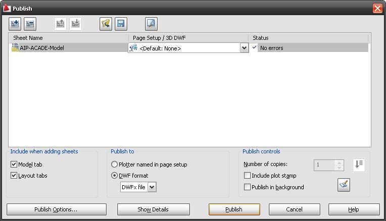
• In Electrical: Use the Publish or the Plot command (Publish provides more options, such as Batch
Publishing). The Publish dialog box is shown below.
• In Inventor: Use the or command. Click in the Save
dialog box when using the latter command. The Publish Drawing dialog box is shown below.
Option Description
Express Publishes the selected file.
Complete Publishes the selected file and all
references. The Custom option is
similar to Express but with more
options.
Enable Enables you to restrict Markups,
Measure/Printing Printing, and Measurements. You can
and Markups also password protection on the
document.
16Can’t We All Get Along? Importing AutoCAD® Electrical Data to Autodesk® Inventor® Cable and Harness
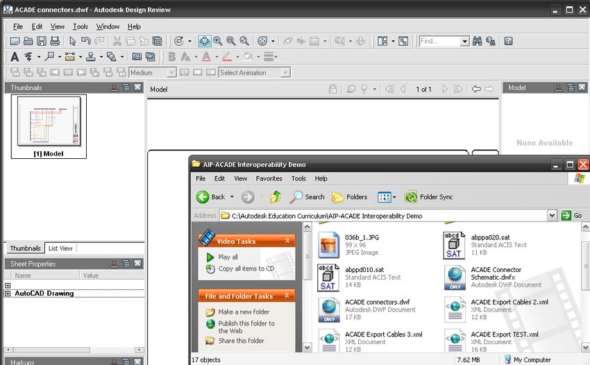
Combining the Design
Once you’ve completed a design, the last step is to combine the Electrical and Inventor files. Consider that
the manager of the Electrical and Mechanical group wants to see both sets of prints, but does not want to
search or minimize through multiple windows. A DWF file from Electrical and Inventor can be combined for a
complete look at the design in a lightweight format. Two major advantages is they cannot accidently change
the design and they do not need the source CAD programs, just Design Review (available for Free).
To combine multiple DWF or DWFx files into a single file, you can use one of the following methods:
• Open Design Review, and drag and drop the merging files from Windows Explorer into the
Thumbnails area of Design Review to create a new file.
• Press or , and then select two DWF or two DWFx files in Windows Explorer. Right-click
and select Merge. Select a new name for the file (note that a DWF and DWFx will not merge).
17Can’t We All Get Along? Importing AutoCAD® Electrical Data to Autodesk® Inventor® Cable and Harness
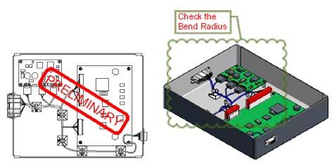
Mark Up and Comparing Revisions
Design Review enables you to mark up a design in numerous ways. The following Design Review Markup
tools are beneficial for the red-liner/checker:
Screenshot tools (to make more sheets in Design
Review to eliminate clutter/obscurity).
Stamps (standard and custom).
Revision Clouds (includes many different styles and
shapes).
Measurement tools (length, polylines, area, etc.).
Options to specify the type of markup (Review or
Question the design).
Current Design Review roundtrip work is only available with 2D sheets, not 3D. Therefore, if a markup is
made on the 3D model, it will not come through with the command from Inventor or
Electrical and 2D will not work correctly from a merged DWF. To avoid this, try to develop a habit of having
Design Review open at the same time as an engineering design change or quick fix.
To compare geometry from different DWF or DWFx files (different revision levels), select Tools > Compare in
the Design Review menu bar. Select a file to compare with and then select the sheet in that file. Currently,
you can only compare 2D sheets, but you will be able to see additions and deletions in your design. Click
in the Compare dialog box to select colors for the additions and deletions. The images below
show the original and compared geometry.
Original: Without Routed Wires (Revision A) Compared: Referencing file with Routed Wires (Revision B)
Class Summary: With Autodesk Inventor Professional, AutoCAD Electrical, and Autodesk
Design Review, you can more easily document, share, and revise an entire project with very little
redundant data. In addition, you can create the documentation needed after a design is shipped or
when repair work is needed. Digital Prototyping your company’s data will save you time, money,
paper, internal confusion, and help bring your product to market that much quicker.
18You can also read