EVOCHARGE EVSE CHARGING STATION - (EVSE, iEVSE, iEVSE Plus) User Manual & Installation Guide
←
→
Page content transcription
If your browser does not render page correctly, please read the page content below
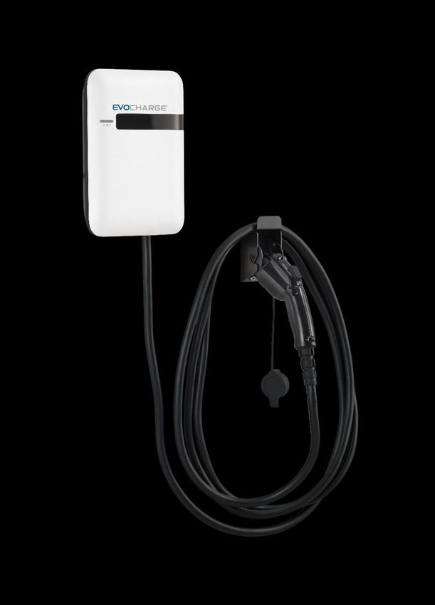
EVOCHARGE® EVSE CHARGING STATION
(EVSE, iEVSE®, iEVSE® Plus)
               User Manual & Installation Guide
                                                                 Revision 1.3
                  French Translation can be located at phillipsandtemro.com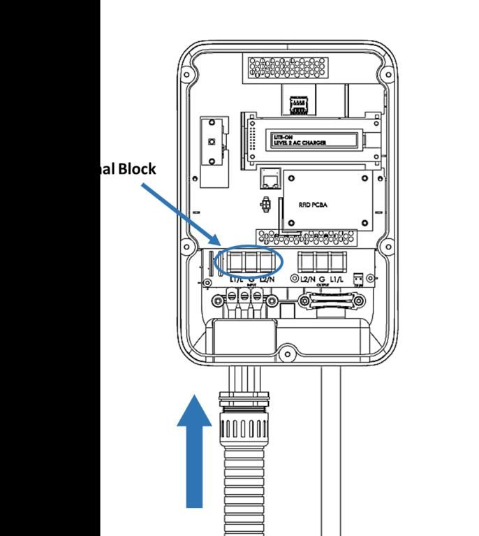
User Manual Rev 1.3

IMPORTANT SAFETY INSTRUCTIONS
This document contains instructions and warnings that must be followed when installing and using the Electric Vehicle
Supply Equipment (EVSE). Before installing or using the EVSE, read this entire document as well as WARNING and
CAUTION markings in this document.

Safety Instructions
The symbols used have the following meaning:

         WARNING: RISK OF PERSONAL INJURY

         WARNING: RISK OF ELECTRIC SHOCK

         WARNING: RISK OF FIRE

         CAUTION: RISK OF DAMAGE TO THE EQUIPMENT

   • The charging station must be installed, adjusted, and repaired only by a licensed electrician.

   • Make sure that the materials used, and the installation procedures follow local building codes and
     safety standards.

   • The information provided in this manual in no way exempts the user of responsibility to follow all
     applicable codes or safety standards.

   • This document provides instructions for the charging station and should not be used for any other
     product. Before installation or use of this product, review this manual carefully and consult with a
     licensed contractor, licensed electrician, or trained installation expert to make sure of compliance with
     local building codes and safety standards.

   •         CAUTION: To reduce the risk of fire, connect only to a circuit provided with the minimum branch
       circuit overcurrent protection requirements in accordance with the National Electrical Code, ANSI/NFPA
       70, and the Canadian Electrical Code, Part I, C22.1.

EVOCHARGE EVSE User Manual & Installation Guide                                                                     1
Part No. 701032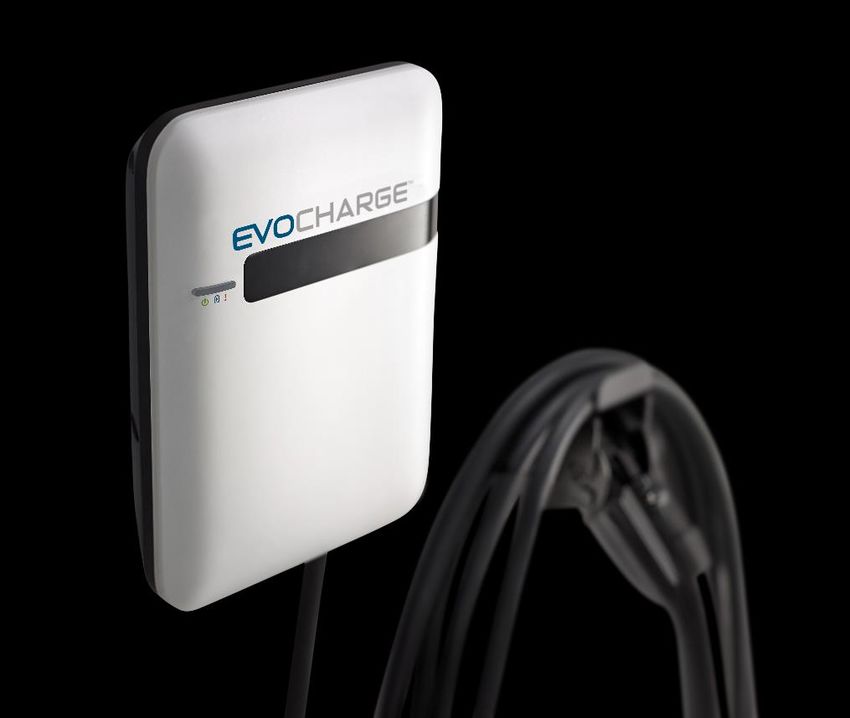
User Manual Rev 1.3

   Repair and Maintenance Clause
   • All EVOCHARGE products do not require routine maintenance however, periodic inspections should be conducted
     to ensure that all parts remain in good working order and no damage exists. Do not attempt to open,
     disassemble, repair, tamper with, or modify any components of the products – the products are not user
     serviceable. Contact EVOCHARGE for any repairs.
   • Only licensed electricians can repair or maintain the charging station. It is forbidden for general users to repair or
     maintain it. Turn off input power before performing any repairs or maintenance to the charging station.

   FCC Declaration of Conformity
   • This charging station complies with part 15 of the FCC Rules. Changes or modifications the charging
     station not expressly approved by the manufacturer could void FCC compliance.
   • Operation is subject to the following two conditions: (1) This charging station may not cause harmful
     interference, and (2) this device must accept any interference received, including interference that may
     cause undesired operation.

   OVERALL WARNINGS & CAUTIONS
         WARNING: RISK OF ELECTRIC SHOCK
         Basic precautions should always be followed when using electrical products, including the
         following:
          •   Read all the instructions before using this product.
          •   This device should be supervised when used around children.
          •   Do not put fingers into the EV connector.
          •   Do not uses this product if the flexible power cord or EV cable is frayed, has broken
              insulation, or any other signs of damage.
          •   Do not use this product if the enclosure or the EV connector is broken, cracked, open, or
              shows any other indication of damage.
           WARNING: RISK OF ELECTRIC SHOCK
           Improper connection of the equipment grounding conductor can result in a risk of electric
           shock. Check with a qualified electrician or serviceman if you are in doubt as to whether the
           product is properly grounded.
           WARNING: RISK OF ELECTRIC SHOCK
            • Do not touch live electrical parts.
            • Incorrect connections may cause electric shock.
           WARNING: This equipment is intended only for charging vehicles that do not require
           ventilation during charging. Please refer to your vehicle’s owner’s manual to determine
           ventilation requirements.

EVOCHARGE EVSE User Manual & Installation Guide                                                                         2
Part No. 701032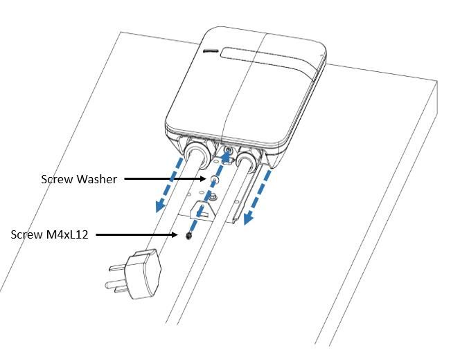
User Manual Rev 1.3

Product Features
EVOCHARGE® EVSE Electric Vehicle Charging Station (EVSE)
    •   J1772 AC Level 2 (208-240 VAC), 32A Continuous Rated (7.7 kW)
    •   Adjustable Maximum Current Output (32A, 24A, 16A) to Support Multiple Circuit Ratings (40A, 30A, 20A)
    •   Modern, Elegant & Compact Design: EVSE form factor smaller than a standard sheet of letter-size paper
    •   Robust Construction, Certified for Outdoor Use: Robust, durable design; tamper-resistant features; NEMA 4
        certified for outdoor and indoor use
    •   Simple Operation: No user interface required with EVSE, simply Plug-in to your EV to initiate charging
    •   Cable & Connector Management: Standard Connector and Cable Holster, Optional EVOREEL® & Retractor Cable
        Management Systems available from EVOCHARGE.
    •   Portable: Standard Plug-in Configuration for easy portability
    •   Simple, Flexible Mounting Options: Wall Mount (including single stud mount), Pedestal (available from
        EVOCHARGE), Bollard/Pole (Single & Dual Port)
    •   UL & cUL Listed, File Number: E469990

EVOCHARGE EVSE User Manual & Installation Guide                                                                3
Part No. 701032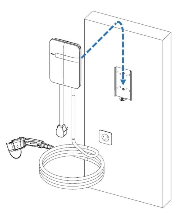
User Manual Rev 1.3

Adjustable Maximum Current Output to Support Multiple Circuit Ratings
The EVOCHARGE EVSE charging station product features the ability to adjust the maximum Charging Station current
output to allow the use of a 40A (or greater), 30A, or 20A Dedicated Circuit as follows:

        •   40A (or greater) Circuit Rating:       To support 32A (7.68 kW) maximum Charging Station output
        •   30A Circuit Rating:                    To support 24A (5.76 kW) maximum Charging Station output
        •   20A Circuit Rating:                    To support 16A (3.84 kW) maximum Charging Station output

    Notes on Circuit Requirements and Amperage settings:
    • The Charging Station Default Factory Maximum Current Output Setting is 32A (7.68 kW) for use with a 40A (or
       greater) Circuit Rating – Please refer to Adjusting Maximum Current Output on page 9 when using a 30A or 20A
       Circuit Rating.
    • To obtain the fastest charging capability of 32A, a 40A (or greater) Circuit Rating must be used.
    • The Circuit must be a DEDICATED CIRCUIT 208-240 VAC, 50-60 Hz, Single Phase
    • Per National Electric Code (NEC), only 80% of the circuit rated load may be utilized, hence the higher Circuit
       Ratings Requirement relative to maximum Charging Station output)

The ability to utilize alternate circuit ratings can be beneficial in the instance the location of installation cannot support a
40A or greater circuit, or in instance where an existing 30A or 20A dedicated circuit is already installed.

Security and Tamper Feature
In addition to the lock screw that secures the EVOCHARGE EVSE charging station to the wall mount bracket (Refer to
Section 2.3, Note 3., Installing the Charging Station), if desired, a feature is included as part of the charging station and
wall mount bracket to install a small padlock for added security and tamper benefits. This feature is located at the
bottom of the charging station near the charging station – wall bracket lock screw.

Self-Monitoring and Recovery | Power Outage Recovery
When a charging session is interrupted due to a temporary error condition, the charging station will automatically
restart charging when the cause of the temporary error condition returns to normal. The status indicator lights remain
flashing RED until the error condition is resolved.

•   Temporary error conditions include: Over Current, Over Voltage, Under Voltage, and Over Temperature.
•   For Over Current (OC) conditions: The charging session will be stop while OC occurs. After recovery from OC for 30
    seconds, the charging station will automatically restart charging for three times.
•   When charging session stopped due to CCID trip, the charging station will try to restart after 15 minutes for 3 times.

When power resumes after an outage, the charging station restarts automatically with a delay ranging from 120 to 720
seconds. The delay is designed to avoid impacting the utility grid when multiple charging stations are in the same area
attempting to resume charging simultaneously.

EVOCHARGE EVSE User Manual & Installation Guide                                                                              4
Part No. 701032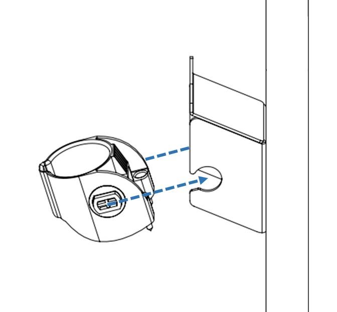
User Manual Rev 1.3

Product Specifications
EVOCHARGE EVSE Electric Vehicle Charging Station (EVSE)
     Description                  Specifications
     Connector / EVSE Level       SAE J1772; AC Level 2
     Max Output Rating            32A; 7.68 kW Maximum Output – For use with 40A (or greater) Circuit Rating
     Alternate Adjustable         24A; 5.76 kW Maximum Output – For use with 30A Circuit Rating
     Output Ratings               16A; 3.84 kW Maximum Output – For use with 20A Circuit Rating
     Electrical Circuit / Input   208-240VAC, 50/60 Hz.; Circuit Requirement: Dedicated; Branch Breaker: Double
     Power Requirements           pole; Circuit Conductors: Line 1, Line 2, Earth Ground
                                  Standard: Plug-in, NEMA 6-50 Plug (Removable for Hardwire Connection); iEVSE
     Input Power Connection
                                  Standard: Hardwire
     Charging Station Color       Standard: White
     Installation Rating          NEMA 4, Indoor/Outdoor Rated
     Operational Ratings          Temperature: -22⁰F to 122⁰F (-30⁰C to 50⁰C); Humidity: 95% RH non-condensing
     Mounting                     Wall or Pedestal Installation (Optional EVOREEL supports Overhead Mounting)
     Overall Dimensions           EVSE: 11.0 x 7.5 x 3.2 inches (28.0 x 19.0 x 8.1 cm)
     Display & Indicators         LED Charge Status Indicators (Power/Ready, Charging, Fault)
                                  Standard: Connector/Cable Holder
     Cable Management
                                  Optional: EVOREEL & Retractor Cable Management
     Standards & Compliance       UL & cUL Listed, File Number: E469990; SAE J1772, UL 2594, UL 355, CSA

EVOCHARGE EVSE User Manual & Installation Guide                                                                   5
Part No. 701032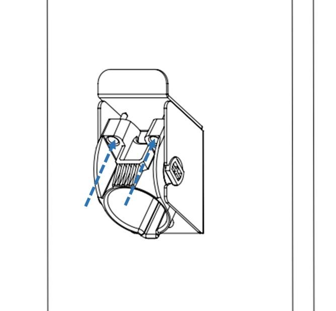
User Manual Rev 1.3

                                   SAVE THESE INSTRUCTIONS
Manual Contents
1   Introduction & Unpacking ..................................................................................................................... 7
             Unpacking ................................................................................................................................... 7

2   Installation ............................................................................................................................................ 8
             Before Installation....................................................................................................................... 8

             2.1.1       Installation Planning & Service Wiring ........................................................................... 8

             2.1.2       Grounding Instructions .................................................................................................. 9

             2.1.3       Adjusting the Charging Station Maximum Current Output Setting (Optional) .............. 9

             Tools & Parts Required for Installation ..................................................................................... 11

             Install the Charging Station ....................................................................................................... 11

             Input Wiring Connection (Optional Hardwire Connection Only) .............................................. 14

             Install the Plug and Cable Holder .............................................................................................. 16

3   Operations........................................................................................................................................... 19
             Charging Status Indicators ........................................................................................................ 19

             Charging your Electric Vehicle (EV) ........................................................................................... 20

             3.2.1       Connect and Charge ..................................................................................................... 20

             Stop Charging ............................................................................................................................ 20

             3.3.1       Self-Monitoring and Recovery (Auto Restart) .............................................................. 20

             3.3.2       Power Outage Recovery ............................................................................................... 20

             General Product Care and Use Information ............................................................................. 21

EVOCHARGE EVSE User Manual & Installation Guide                                                                                                                   6
Part No. 701032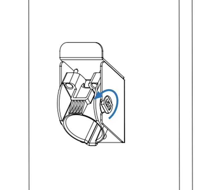
User Manual Rev 1.3

1 Introduction & Unpacking
This user manual applies to the EVOCHARGE EVSE for Plug-in Hybrid Electric Vehicles (PHEVs) and Electric Vehicles (EVs).

      Unpacking
Unpackage all items and confirm the contents as noted below.

*Please Note: Do Not discard the packaging material before removing the Plug (Connector) & Cable Holder as well as the
Mounting Fasteners for both the Charging Station Mounting Bracket and Connector & Cable Holder – these items are
packaged within a compartment of the charging station cardboard packaging.

                                                                                                    (4 pcs.)

                                                  Figure 1-1 Box Contents

                                                  Table 1-1 Box Contents
       Item                Description                 Qty.                         Notes
         1     Charging Station                         1
         2     Charging Station Mounting Bracket        1     Bracket is Attached to Charging Station
                                                              Holder is packaged within cardboard compartment
         3     Connector & Cable Holder                 1
                                                              of charging station packaging
                                                              2 Fasteners for Charging Station Mounting Bracket
         4     Mounting Fasteners                       4
                                                              2 Fasteners for Connector & Cable Holder

EVOCHARGE EVSE User Manual & Installation Guide                                                                      7
Part No. 701032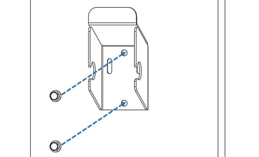
User Manual Rev 1.3

2 Installation
      Before Installation
2.1.1 Installation Planning & Service Wiring
         WARNING: RISK OF ELECTRIC SHOCK
         • Do not touch live electrical parts.
         • Incorrect connections may cause electric shock.
         • Disconnect the power supply to the charging station and verify no power is present before installing,
            adjusting, or repairing the charging station. Failure to do so may result in physical injury or damage to
            the power supply system and the charging station.

The charging station must be installed only by a licensed electrician in accordance with the provisions of the local
electrical industry construction and should comply with national electrical codes and standards.

Before installing the charging station, make sure you have read these instructions in this manual and fully understand its
contents.

Appropriate protection is required when connecting to a main panel/switchboard. The tools and parts used as outlined
in the section “Tools & parts required for installation”.

Prior to mounting, determine location of an acceptable mounting support. All charging station products must be
anchored into a mounting support such as a 2” x 4” stud or a solid concrete wall, using mounting hardware that is
appropriate for the surface on which you are mounting. DO NOT mount this unit directly to a stucco/drywall/wall board.
If installing to a wood stud, use the lag screws provided and ensure the mounting plate is positioned on the centerline of
the stud. If mounting onto a concrete, block, or brick wall, use an appropriate anchor for the type of wall on which you
are installing the unit.

Prior to mounting, locate an available electrical source that can support the following Input Requirements for the
Charging Station Per National Electric Code (NEC) requirements:
   • 32A Maximum Output Setting (Default Factory Setting): a DEDICATED CIRCUIT rated for 40A; 208-240 VAC, 50-60
       Hz, Single Phase must be used. Circuits rated greater than 40A may also be used.
   • 24A Maximum Output Setting (Optional Setting): a DEDICATED CIRCUIT rated for 30A; 208-240 VAC, 50-60 Hz,
       Single Phase must be used. Note: Please refer to Adjusting Maximum Current Output on page 9.
   • 16A Maximum Output Setting (Optional Setting): a DEDICATED CIRCUIT rated for 20A; 208-240 VAC, 50-60 Hz,
       Single Phase must be used. Note: Please refer to Adjusting Maximum Current Output on page 9.
   • Additionally, a Double Pole Circuit Breaker of the circuit rating must be used. The Charging Unit has a built in GFCI
       protection; do not provide any additional GFCI protection upstream of the charging unit.
   • The Charging Stations can connect (plug into) a Standard NEMA 6-50 Receptacle or the unit can be hardwired.

          CAUTION: The service wiring in this section are specific to North America only. Before installing the
          Charging Station, identify the type of utility service connection available onsite. If you have unsure about
          the type of connection available at the service panel, contact your utility service provider.

EVOCHARGE EVSE User Manual & Installation Guide                                                                          8
Part No. 701032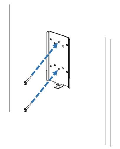
User Manual Rev 1.3

2.1.2 Grounding Instructions
The charging station must be implemented equipment grounding through a permanent wiring system or an equipment
grounding conductor. Use a wire with a dedicated grounding wire and a ring terminal and connected to the equipment
ground terminal block for grounding.

2.1.3 Adjusting the Charging Station Maximum Current Output Setting (Optional)
         WARNING: RISK OF ELECTRIC SHOCK
         • Do not touch live electrical parts.
         • Incorrect connections may cause electric shock.
         • Disconnect the power supply to the charging station and verify no power is present before installing,
            adjusting, or repairing the charging station. Failure to do so may result in physical injury or damage to
            the power supply system and the charging station.
         • Electrical Power MUST remain OFF and DISCONNECTED before setting or changing the DIP switch. A
            non-conductive object MUST be used to adjust the DIP switch settings, failure to do so may result in risk
            of electrical shock and damage to the equipment.

The EVOCHARGE EVSE charging station product features the ability to adjust the maximum Charging Station current
output to allow the use of a 40A (or greater), 30A, or 20A Dedicated Circuit as follows:
        • 40A (or greater) Circuit Rating:       To support 32A (7.68 kW) maximum Charging Station output
        • 30A Circuit Rating:                    To support 24A (5.76 kW) maximum Charging Station output
        • 20A Circuit Rating:                    To support 16A (3.84 kW) maximum Charging Station output

The Charging Station Default Factory Maximum Current Output Setting is 32A (7.68 kW) for use with a 40A (or greater)
Circuit Rating. To adjust the Maximum Current Output Setting when using a 30A or 20A Circuit Rating:
    1. Place the Charging Station on a flat surface, front cover down with protection under the cover to avoid
         scratching damage to the cover.
    2. Remove the Charing Station front cover by loosening the (5) Torx screws at the rear of the charging station.

                                   Five Torx screw locations to remove the Charging Station Cover

EVOCHARGE EVSE User Manual & Installation Guide                                                                     9
Part No. 701032
User Manual Rev 1.3
CAUTION: The LED board is attached to the charging station front cover and the charging station circuit
board. Use care to not place force or strain on the wiring harness when the cover screws are removed.
Failure to do so may result in damage to the charging station, which is not covered under warranty.
3. With the (5) Torx screws loosened, hold the front cover in place to avoid strain being placed on the LED board
wiring harness and flip the charging station over on the flat surface so that the front cover is on top. Once this is
completed, gently lift the charging station front cover and place to the right side of the charging station unit.
Again, use care to not place force or strain on the wiring harness when the front cover screws are removed.
Failure to do so may result in damage to the charging station.
4. With the front cover placed to the side, locate the DIP switch on the charging station circuit board. The DIP
switch is a 4-position switch on the main circuit board, located directly to the left of the LED board wiring
harness connector.
4-Position DIP Switch
WARNING: RISK OF ELECTRIC SHOCK
• Do not touch live electrical parts.
• Incorrect connections may cause electric shock.
• Disconnect the power supply to the charging station and verify no power is present before installing,
adjusting, or repairing the charging station. Failure to do so may result in physical injury or damage to
the power supply system and the charging station.
• Electrical Power MUST remain OFF and DISCONNECTED before setting or changing the DIP switch. A
non-conductive object MUST be used to adjust the DIP switch settings, failure to do so may result in risk
of electrical shock and damage to the equipment.
5. To Adjust the Maximum Current Output to either 24A or 16A, use a non-conductive object to adjust the DIP
switch settings as follows:
DIP Switch Setting
Maximum Current Output DIP 1 DIP 2 DIP 3 DIP 4
(Picture)
32A Maximum Current Output
ON OFF ON OFF
(Factory Default Setting)
24A Maximum Current Output ON OFF OFF ON
16A Maximum Current Output ON OFF OFF OFF
6. Once the DIP Switch Setting is adjusted, reassemble the charging station.
6-1. Reinstall the LED wiring harness to the charging station circuit board and install the charging station font
cover using the following torque force to secure the (5) Torx screws:
Screw Torque
M4 16 kgf.cm 13.88 lb-in
EVOCHARGE EVSE User Manual & Installation Guide 10
Part No. 701032User Manual Rev 1.3
Tools & Parts Required for Installation
Table 2-1 Tools & parts required for installation
Tool Size Source of Supply Remark
Mounting Bracket 194 x 109 x 9 mm Included with Product For installing charging station to the wall/structure
Connector & Cable Holder 58 x 58 x 70 mm Included with Product To store the EV charging Plug and Cable
For installing the Mounting Bracket & Holder to the
Mounting Fasteners x4 1/4” or M6 Included with Product
wall/structure
Socket 5/16” or 8mm Commercially Available For Mounting Fasteners
Torx Driver T20 Commercially Available For Charging Station Lock Screw and Cover Screws
Philips Screwdriver PH3 Commercially Available For Holder Installation and Optional Hardwire Install
Torque Wrench 6 ~ 50 kgf-cm Commercially Available For all fasteners
UL1015 (recommended) for Input Wiring - Only
Wire, Copper 8 AWG Commercially Available
Required for Optional Hardwire Connection
Heat Shrink Tube x3 For 8 AWG wire Commercially Available Only Required for Optional Hardwire Connection
Terminal x3 For 8 AWG wire Commercially Available Only Required for Optional Hardwire Connection
Conduit 1” Commercially Available Only Required for Optional Hardwire Connection
Install the Charging Station
1. Secure the charging station mounting bracket to the wall or other suitable structure with appropriate mounting
screws. If installing to a wall, ensure the screws are anchored into a suitable wall stud.
2. Follow applicable accessibility requirements for the mounting position. The unit shall be mounted at a sufficient
height from ground such that the height of the storage means for the coupling device is located between 24
inches (0.6 m) and 48 inches (1.2 m) from ground per NEC Article 625.
3. The mounting bracket has ten screw holes to support attachment to multiple mounting surfaces. For most
installation, including attached the charging station to a single wall stud, only two screws will be used to attach
the mounting bracket. In this case, the screws should pass (install) through the middle two vertical screw holes
of the mounting bracket as shown in Figures 2-1 & 2-2.
EVOCHARGE EVSE User Manual & Installation Guide 11
Part No. 701032User Manual Rev 1.3
Figure 2-1 Installing the mounting bracket Figure 2-2 Screw holes of mounting bracket
Mounting Screw Recommendations:
a. For finished walls supported by wood studs, use 1/4” or M6 tapping screws. (Supplied)
b. For masonry walls, use M6 mechanical screws. (Commercially available)
c. Use following torque force:
Screw Torque
M6 50 kgf.cm 43.4 lb-in
1/4” 50 kgf.cm 43.4 lb-in
4. As shown in Figures 2-3 & 2-4, mount the charging station onto the mounting bracket and secure the lock screw.
3-1. Tighten the installed M4 screw and screw washer to fix charging station on mounting bracket.
3-2. Use following torque force:
Screw Torque
M4 16 kgf.cm 13.88 lb-in
EVOCHARGE EVSE User Manual & Installation Guide 12
Part No. 701032User Manual Rev 1.3
Figure 2-3 Charging station and mounting bracket Figure 2-4 Screw locking position
5. For Plug-in (NEMA 6-50) models, Plug in the power cord to the NEMA 6-50 Wall Outlet/Receptacle. The NEMA
outlet should be located no less than 20~26” from the ground or as defined by applicable state, local and
national electrical codes and standards.
Figure 2-5 Plug in the power cord
EVOCHARGE EVSE User Manual & Installation Guide 13
Part No. 701032User Manual Rev 1.3
Input Wiring Connection (Optional Hardwire Connection Only)
7. Choose the appropriate conduit in accordance with all applicable state, local and national electrical codes and
standards.
Figure 2-6 Conduit.
8. Using the appropriate tool, clamp the wire terminal to the copper wire. For non-insulated terminals, use heat
shrink tube to cover the non-insulated portion of the terminal.
Figure 2-7 Copper terminal, heat shrink tube and copper wire.
9. Connecting the electrical wiring to the charging station.
9-1. Place the Charging Station on a flat surface, front cover down with protection under the cover to avoid
scratching damage to the cover.
9-2. Remove the Charing Station front cover by loosening the (5) Torx screws at the rear of the charging station.
Figure 2-8 Five Torx screw locations to remove the Charging Station Cover
CAUTION: The LED board is attached to the charging station front cover and the charging station circuit
board. Use care to not place force or strain on the wiring harness when the cover screws are removed.
Failure to do so may result in damage to the charging station, which is not covered under warranty.
9-3. With the (5) Torx screws loosened, hold the front cover in place to avoid strain being placed on the LED
board wiring harness and flip the charging station over on the flat surface so that the front cover is on top.
Once this is completed, gently lift the charging station front cover and place to the right side of the charging
EVOCHARGE EVSE User Manual & Installation Guide 14
Part No. 701032User Manual Rev 1.3
station unit. Again, use care to not place force or strain on the wiring harness when the front cover screws
are removed. Failure to do so may result in damage to the charging station.
9-4. With the front cover placed to the side, remove the Terminal Block plastic cover and use Philips screwdriver
to release terminal screws of the NEMA 6-50 Plug. Loosen the Strain Relief Fitting for the NEMA 6-50 Plug
and Remove the Plug.
9-5. Insert the wire end passing through the conduit and insert them into the input wiring hole. (Use Red wire for
L1, Black wire for L2, Green-yellow wire for G). Attach the copper wire on the corresponding terminal block.
Use the following wire and torque force when connecting to input terminal block, using conductor type
other than RHH, RHW and RHW-2 with outer covering.
Model Terminal Conductor Screw Rating Torque
EVOCHARGE EVSE L1, L2, G 8 AWG M4 90C, copper wire 16 kgf.cm 13.88 lb-in
Figure 2-7 Input wiring
CAUTION: To reduce the risk of fire, connect only to a circuit provided with the appropriate
amperes minimum branch circuit overcurrent protection in accordance with the National
Electrical Code, ANSI/NFPA 70, and the Canadian Electrical Code, Part I, C22.1.
Model Current Setting Circuit Rating Requirement
EVOCHARGE EVSE 32A 40A or greater
EVOCHARGE EVSE 24A 30A
EVOCHARGE EVSE 16A 20A
10- Once the input wiring and conduit are connected, reassemble the charging station.
10-1. Reinstall the LED wiring harness to the charging station circuit board and install the charging station font
cover using the following torque force to secure the (5) Torx screws:
Screw Torque
M4 16 kgf.cm 13.88 lb-in
EVOCHARGE EVSE User Manual & Installation Guide 15
Part No. 701032User Manual Rev 1.3
Install the Plug and Cable Holder
1. Separate the holder from hook.
Figure 2-8 Separate the holder
2. The Holder can be installed at any location near the charging station. Once the holder installation location is
determined, secure the holder bracket to the wall with appropriate screws x2 (1/4” or M6).
Figure 2-9 Secure the hook
3. Position the plastic holder insert face up and install into the holder bracket.
EVOCHARGE EVSE User Manual & Installation Guide 16
Part No. 701032User Manual Rev 1.3
Figure 2-10 Secure the holder
4. Next, rotate the holder insert down.
Figure 2-11 Rotate the holder
5. With the holder insert in the down position, tighten the (2) lock/set Philips screws located at the top of the
plastic holder component until snug (do not overtighten). The screws ensure that the plastic holder component
remains secured to the holder bracket.
EVOCHARGE EVSE User Manual & Installation Guide 17
Part No. 701032User Manual Rev 1.3
Figure 2-12 Lock screws
6. Insert EV charging connector into the holder.
Figure 2-13 Insert EV Charging Connector into Holder
EVOCHARGE EVSE User Manual & Installation Guide 18
Part No. 701032User Manual Rev 1.3
3 Operations
Charging Status Indicators
Table 3-1 Charging status indicators
LED Indicator Description Definition
Not illuminated Power Off
Green Steady Ready
Flashing green (Fast): Authorized, waiting for
Green Flashing EV to initiate charge event.
Flashing green (Slow): Suspend (Occupying)
Blue Flashing Flashing blue (Slow): Charging
Red Steady Unrecoverable Fault
Red Flashing Recoverable Fault
Yellow Steady Out of Service
Yellow Flashing Booting / Firmware Upgrade in process
*Note:In the instance the “Red Steady” or “Red Flashing” Fault light remains, it is recommended that you:
• Unplug the charging Connector from your EV
• Turn off the power to the Charging Station by switching the upstream circuit breaker to the “OFF” position
• With the circuit breaker in the “OFF” position, wait 1-2 minutes and then switch the upstream circuit breaker
back to the “ON” position
• Confirm the Fault light is no longer present. If the Fault light remains, please contact EVOCHARGE.
EVOCHARGE EVSE User Manual & Installation Guide 19
Part No. 701032User Manual Rev 1.3
Charging your Electric Vehicle (EV)
3.2.1 Connect and Charge
1. Insert the charging Connector into the EV and ensure the connector is fully seated/locked in place.
2. Once complete, the charging session will commence.
Figure 3-1 Connect the charging plug to the EV
Stop Charging
1. Simply unplug the charging station connector from the EV at any time (once the connector button is depressed,
the charging session terminates immediately).
2. Return the connector to the holder.
3.3.1 Self-Monitoring and Recovery (Auto Restart)
When a charging session is interrupted due to a temporary error condition, the charging station will automatically
restart charging when the cause of the temporary error condition returns to normal. The status indicator lights remain
flashing RED until the error condition is resolved.
• Temporary error conditions include: Over Current, Over Voltage, Under Voltage, and Over Temperature.
• For Over Current (OC) conditions: The charging session will be stop while OC occurs. After recovery from OC for 30
seconds, the charging station will automatically restart charging for three times.
• When charging session stopped due to CCID trip, the charging station will try to restart after 15 minutes for 3 times.
3.3.2 Power Outage Recovery
When power resumes after an outage, the charging station restarts automatically with a delay ranging from 120 to 720
seconds. The delay is designed to avoid impacting the utility grid when multiple charging stations are in the same area
attempting to resume charging simultaneously.
EVOCHARGE EVSE User Manual & Installation Guide 20
Part No. 701032User Manual Rev 1.3
General Product Care and Use Information
The exterior of the charging station is designed to be waterproof and dust proof (NEMA 4 Outdoor Rated). However,
periodic cleaning may be required, depending on local conditions. To ensure proper maintenance of the charging
station, follow these guidelines:
• To avoid damaging the finish of the products, only use an automotive grade soft cleaning cloth and if required a mild
soap and water mixture to remove accumulation of dirt and dust. Do not use cleaning solvents to clean any of the
product components. Despite the water resistance of the enclosure, when cleaning it is preferred to not direct
streams of water at the unit – clean with a water damp, automotive grade soft cleaning cloth.
• Make sure the charging connector is put back in the holster after charging to avoid damage.
• Ensure the power cable is stored on the charging station after use to avoid damage.
• If the power cable or the charging connector is damaged, turn off the charging station supply circuit breaker, do not
use the charging station, and please contact EVOCHARGE Customer Support for replacement parts.
• When moving or lifting the unit, always grasp and carry by the charging station plastic body. Never attempt to lift,
move, or carry the unit by any of the electrical cables. Improper handling may cause damage to the unit.
For Additional Products, Field Support and Cable Management solutions visit
www.phillpsandtemro.com or contact us at 1-800-328-6108.
EVOCHARGE EVSE User Manual & Installation Guide 21
Part No. 701032You can also read