The Analysis of Stone Trapping in Tire Tread for Various Road Conditions
←
→
Page content transcription
If your browser does not render page correctly, please read the page content below
MATEC Web of Conferences 335, 03003 (2021) https://doi.org/10.1051/matecconf/202133503003
14th EURECA 2020

 The Analysis of Stone Trapping in Tire Tread for
 Various Road Conditions
 Jun Yi Eugene Gow 1 and Pei Xuan Ku 1,*

 1School of Computer Science and Engineering, Faculty of Innovation and Technology, Taylor’s
 University, 47500, Selangor, Malaysia

 Abstract. A tire tends to trap stones in its tread pattern when the vehicle is
 on a move and this might affects the tire balance due to uneven tread wear
 of tread portion. The study aims to simulate stone trapping performance
 under various tire tread patterns and road conditions as well as assessing the
 performance of tires with stones trapped. The stone trapping phenomena on
 different tire tread pattern were analyzed under dry and wet road conditions.
 The tire models chosen were the symmetrical tire, asymmetrical tire, and
 directional tire. The model of these tires, stone and a flat road surface were
 created using SolidWorks and Fusion360 software and the static structural
 simulation is performed by using finite element analysis method. Tire
 inflation analysis and steady state rolling analysis were conducted to
 evaluate three parameters: total deformation, Von-Mises stress and
 equivalent elastic strain of the tires. It found that all three parameters are
 higher when stone trapped in tire for all tread pattern types. Symmetrical
 tread pattern provides the least wear and tear since it has the lowest
 increment of maximum equivalent elastic strain in both road conditions.
 Stone trapping in tire grooves would impact on the lifespan of the tire.

 1 Introduction
 The occurrence of stone trapping normally happens in a moving vehicle and it varies
 depending on the stone structure. When the vehicle is in a motion, the downward pressure
 exerted by the weight of the tire forces the stone to slide in between the grooves which then
 leads to stone trapping. Stone trapping could cause some of the harmful effect to the tire such
 as affecting the tire balance due to uneven tread wear of the tread portion. Another common
 issue would be the shorter lifespan of the tire which is caused by the tire damage after some
 period due to stone trapping. The type of tire damage includes cuts, impacts, cracks, bulges
 and irregular wear [1]. Sometimes to a certain extent, stone trapping might even lead to
 puncture of tires due to sharp edge of the stone structure. The five main elements of the tire
 tread’s pattern consist of the grooves (longitudinal/lateral), tread blocks, sips, cross slots and
 ribs [2]. Among these few main components of the tire, stones are most found trapped in the
 groove section of the tire.

 *
 Corresponding author: peixuan.ku@taylors.edu.my

© The Authors, published by EDP Sciences. This is an open access article distributed under the terms of the Creative Commons
Attribution License 4.0 (http://creativecommons.org/licenses/by/4.0/).
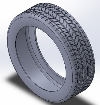
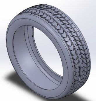
MATEC Web of Conferences 335, 03003 (2021) https://doi.org/10.1051/matecconf/202133503003
14th EURECA 2020

 There are various factors that affect the performance of the tire. These factors include the
 design of tire tread pattern (groove type), inflation pressure, tire load and mechanical
 properties of material. Muniandy et al. [3] found that an increment in inflation pressure by
 50% will decrease the actual contact area by 17% while an increase of tire load by 50% will
 increase the actual contact area by 42%. Fwa et al. [4] had identified that an increase in
 groove depth from 1mm to 9.8mm could reduce the hydroplaning rate by 9.8%. Besides the
 groove depth, the groove shape also plays an important role whereby hydroplaning rate can
 be reduced by an increase of V-cut groove angle of up to 90 degrees. Hydroplaning is defined
 when a vehicle starts to slide uncontrollably due to tires encountering more water than the
 tread can displace and it most commonly occurs by speeding on a wet road. From another
 similar study, Kumar et al. [5] had also identified that the hydroplaning speed can be reduced
 by 1.25 times through increasing the tire inflation pressure from 110 kPa to 165.5 kPa. Apart
 from that, Sreeraj et al. [6] had found that the wear rate of the tire increases with inflation
 pressure and material with high Young’s modulus and density. Meanwhile, Chang et al. [7]
 had identified that wear rate increases with slip rate and mileage while the maximum value
 of the wear depth is found to be on the edge of the tread pattern. In relation to determining
 the wear and tear, elastic strain which is the significance of wear behaviour was found to be
 a more appropriate parameter to determine the wear resistance instead of material property
 such as the hardness alone [8]. According to a similar previous study, it was observed that
 the elastic equivalent stress increases with time whereby higher maximum equivalent elastic
 strain indicates that the tire’s wear and tear is high [9]. Moreover, Wu et al. [10] found that
 friction coefficient is greatly influence by tire tread patterns while the dry road surface shows
 a greater friction coefficient value compared to the wet road surface.
 Based on previous researches, it can be concluded that these studies conducted were
 focusing mainly on the tire tread pattern affecting the stiffness, contact area and pressure,
 hydroplaning rate, wear rate and friction coefficient. However, there were lack of studies that
 relate to the stone trapping mechanism and how the stone trapping could affect the
 performance of the tires. Hence, this research aims to provide an insight on how stone
 trapping in tire tread could have an influence on the safety of road users and lifespan of the
 tire.This brings upon to the objectives of this study which is to simulate stone trapping
 performance under various tire tread pattern geometry and to assess the effect of stone
 trapping has on the tire performance under different road conditions. ANSYS finite element
 analysis (FEA) method was used to conduct the tire inflation and steady state rolling analysis
 to evaluate how stone trapping reacts on different tire tread patterns under different road
 conditions.

 2 Methodology

 2.1 3D CAD modelling

 The geometry of the commercial vehicle tires namely the symmetrical, asymmetrical
 and direction tires were created using SolidWorks software as shown in Fig. 1. The
 specifications of the tire were based on a 15-inch tire (205/60R15) as demonstrated in Table
 1. A simple road surface measuring at a width of 300 mm and 1000 mm in length is also
 created using this software to act as a fixed support for the tire model.
 Fusion360 software was used to create 3 irregular stones model of different shapes and
 sizes. To obtain the stones of different design, a shape of quad ball form was first created
 with the identified dimensions. The span face of this shape was set at 16 units so each form
 can be edited in a translational manner until it mimics the shape of a typical road stones. The
 drawing of these stone models was limit to the geometric specification of the tire groove

 2
MATEC Web of Conferences 335, 03003 (2021) https://doi.org/10.1051/matecconf/202133503003
14th EURECA 2020

 width and depth which is 5 mm and 8 mm respectively. Thus, the stones were modelled in
 the range between 4.5 mm and 6.2 mm in terms of their width and height as shown in Fig. 2.

 Table 1. Tire specifications.
 Description Specification
 Tire width (mm) 205
 Aspect ratio 60
 Height (mm) 123
 Wheel outer diameter (mm) 693
 Rim diameter (mm) 447
 Groove width (mm) 5
 Groove depth (mm) 8

 (a) (b) (c)
 Fig. 1. Tire tread pattern of (a) symmetrical, (b) asymmetrical and (c) directional.

 Fig. 2. 3D CAD model of the irregular stones

 To obtain tire with stones trapped in its groove, the stones were assembled into the desired
 section of the tire’s groove using SolidWorks mate and lock feature. A fixed number of 40
 stones were assembled into every tread pattern. This was solely done to ensure fair
 comparison can be made from this study. Upon obtaining the stone trapped tire, it was then
 mate coincident and concentric to the vertical plane of the road surface and finally a complete
 stone trapped tire on a road surface was formed for simulation purpose.

 3
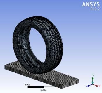
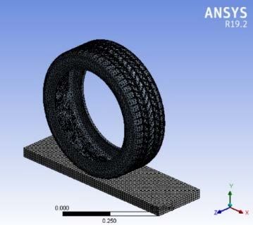
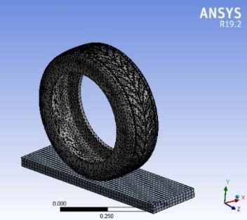
MATEC Web of Conferences 335, 03003 (2021) https://doi.org/10.1051/matecconf/202133503003
14th EURECA 2020

 2.2 Mesh Independency Test
 The stone trapping mechanism and performance of the tires are analyzed through finite
 element analysis method (FEA) using the ANSYS software as this method has proven to be
 a reliable approach in simulating the physical behavior of engineering designs [11]. A mesh
 independence test was done for each of the tire tread patterns to obtain the most suitable mesh
 size for the analysis. This test is first done by obtaining the mesh date from ANYS as shown
 in Table 2. Using the mesh data, graphs of maximum equivalent stress and total deformation
 against the number of elements were plotted which then proceed with the graph analyzing
 part. The points where the trend of the curve starts to become constant was taken and the
 mesh size which correspond to this point was assumed as the most appropriate mesh size for
 this tire tread pattern. This mesh element size is appropriate as it provides the most accurate
 results with the least computing time. Apart from that, the average skewness that correspond
 to the mesh size was also obtained to identify which column of these mesh sizes fall under
 based on the skewness mesh metric spectrum. From the results obtained, it was deduced that
 the mesh size obtained falls under the ‘Very Good’ and ‘Good’ column based on the
 skewness mesh metric spectrum shown in Fig. 3.

 Table 2. Mesh data obtained for all tread pattern.
 Tire Tread Average Skewness
 Mesh size Elements Nodes
 Pattern skewness level
 Symmetrical 0.015 43140 105383 0.47427 Very Good
 Asymmetrical 0.020 58584 121954 0.76819 Good
 Directional 0.020 44448 86991 0.49125 Very Good

 Fig. 3. Skewness mesh metric spectrum [12].

 Fig. 4 demonstrates the meshing of the tire for all tread patterns. A finer mesh was applied
 to the tire’s contact region or the areas of interest where the equivalent stress, total
 deformation and elastic equivalent strain will be obtained from.

 (a) (b) (c)

 Fig. 4. Geometry meshing of (a) symmetrical tire, (b) asymmetrical tire and (c) directional tire.

 4
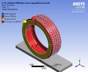
MATEC Web of Conferences 335, 03003 (2021) https://doi.org/10.1051/matecconf/202133503003
14th EURECA 2020

 2.3 Material selection and applying boundary condition

 The tire inflation analysis and steady state rolling analysis were conducted using ANSYS
 19.1 software to evaluate how stone trapping reacts on different tread patterns as well as on
 wet and dry road conditions. Both non-stone trapped and stone trapped tires of all the 3 tread
 patterns tire had undergone these analyses to evaluate the wear and tear rate and tire’s
 behavior. Styrene butadiene rubber and natural rubber were assigned to these tires while
 concrete, available in ANSYS material library was used for the stones and road surface.
 The tire inflation analysis was conducted to determine the tire’s behavior by identifying
 how different tread patterns would react when there is stone trapping. For this analysis, the
 tire models are subjected to the vertical force and displacement at y component so they would
 not rotate out of the x and z plane. A force magnitude of 2750 N was applied to the whole
 body of tire and a uniform pressure of 2 bar or 0.2 MPa was also inflated into the tire through
 applying at the inner region of the tire. Lastly, a fixed support was applied to the bottom
 region of the road surface.
 Meanwhile, the steady state rolling analysis was performed to determine the tire’s wear
 when there is stone trapping and this analysis was analyzed in both wet and dry road
 condition. For this analysis, same boundary conditions were set whereby the displacement,
 force, fixed support and pressure were applied at the same regions mentioned above.
 Additional contact joints in terms of the revolute and translational were applied to the
 sidewall and front surface of the road respectively. This was done to allow the tire to rotate
 at a fixed position without rolling out from the road. The displacement set for this analysis
 was 100 m and in order to do so, the rotational velocity of the tire was fixed at 100 m/s and
 the rotating period was determined at 1 s. This principle of simple average velocity formula
 was used in this case to ensure the displacement set for this analysis. Furthermore, the road
 was made frictional where the friction coefficient was set at 0.7 to represent the dry road
 while 0.4 to represent the wet road [13].

 Fig. 5. Boundary condition set for the analysis.

 Table 3. Material properties [6].
 Styrene Butadiene
 Parameters Natural Rubber Concrete
 Rubber
 Density (kg/m3) 950 1100 2300
 Young’s Modulus (MPa) 10 6 30000
 Poisson Ratio 0.48 0.49 0.18
 Tensile Yield Strength (MPa) 24.54 20 -
 Tensile Ultimate Strength (MPa) - - 5

 5
MATEC Web of Conferences 335, 03003 (2021) https://doi.org/10.1051/matecconf/202133503003
14th EURECA 2020

 2.4 Data Simulation
 For the tire inflation analysis, the observation on different tire tread behavior in terms of the
 shape deformation was done through analyzing the total deflection and Von-Mises stress.
 The focus of tire parts in this analysis would be the belts and sidewalls.
 The steady state rolling analysis was conducted to determine the wear resistance of the
 tire in both wet and dry surfaces. Maximum equivalent elastic strain was obtained from this
 analysis to track which tread pattern has the most wear and tear regarding stone trapping. A
 comparison of results between non stone-trapped tire and stone trapped tire were done for
 each of the tread patterns to identify the relative difference in the Von-Mises stress and total
 deformation. The relative difference can be obtained through Eq. (1) as follows:

 −
 = 100% (1)

 *The stone trapped value refers to value of maximum Von-Mises stress and total deformation
 for stone trapped and vice versa.
 Upon obtaining the relative difference of the results for all the tread patterns, these results
 were then compared again with one another to identify which tire tread pattern has the least
 and most effect on stone trapping mechanism. As for the steady state rolling analysis, same
 comparison was done in this analysis like the tire inflation analysis with the exception that it
 was compared on different road surface (wet and dry) to identify what will the impact of the
 friction coefficient has on stone trapping mechanism. Besides that, the identification on
 whether stone trapping will affect the lifespan of the tire can be deduce in this analysis as
 well.

 3 Results & Discussion

 3.1 Analysis of tire inflation

 The Von-Mises stress defines as an actual stress which involves both combined shear and
 tensile stress to predict a yielding of a material. Meanwhile, the total deformation can be put
 as a change in shape of a body which resulted from the stress applied. In this study, both
 components mentioned were evaluated using ANSYS where Fig. 6 and Fig. 7 demonstrate
 the result of this analysis.

 (a) (b)

 Fig. 6. Equivalent Von-Mises stress of symmetrical tire with (a) non-stone trapped and (b) stone
 trapped.

 6
MATEC Web of Conferences 335, 03003 (2021) https://doi.org/10.1051/matecconf/202133503003
14th EURECA 2020

 (a) (b)

 Fig. 7. Total deformation of symmetrical tire with (a) non-stone trapped and (b) stone trapped.

 Table 4. Maximum equivalent Von-Mises stress and total deformation of tire tread patterns (styrene
 butadiene rubber).
 Non stone trapped Stone trapped
 Maximum Maximum
 Type of tread
 Equivalent Total Equivalent Total
 pattern
 Von-Mises Deformation, m Von-Mises Deformation, m
 Stress, MPa Stress, MPa
 Symmetrical 11.47 0.0346 15.02 0.1277
 Asymmetrical 19.19 0.1435 24.84 0.3391
 Directional 9.35 0.07457 13.98 0.1408

 According to Fig. 6 and Fig. 7, whereby tire inflation analysis was performed on the
 symmetrical tread pattern, it was observed that the equivalent Von-Mises stress and total
 deformation were higher when there is stone trapped. Likewise, this goes the same for the 2
 other type of tread patterns, asymmetrical and directional, where the equivalent Von-Mises
 stress and total deformation are greater for the stone trapped (Table 4). From the results
 tabulated in Table 4, it is observed that the maximum equivalent Von-Mises stress ranges
 between 9.35 to 24.84 MPa. Similarly, a previous study conducted by Ihueze et al. [14] had
 also evaluated that the maximum Von-Mises stresses value were found to be at the range
 between 5 to 30 MPa whereby the predominant values were located at the sidewall region.
 Besides, it can also be seen that the location of the maximum stress and total deformation
 are acting upon the sidewalls of the tire regardless if its stone trapped or non-stone trapped.
 According to Spiegel and Limbrunner [15], it is understood that these stresses are developed
 at the sidewalls when various layers of material tend to slip with respect to one another from
 the force applied. Also, in this study, a maximum pressure of 2 bars or 0.2 MPa that is inflated
 into the inner region of the tire has induced the sidewalls to create resisting forces to put
 against the inflation pressure that is acting within the sidewall of the tire. The resisting forces
 which compose of shear and tensile stresses are then distributed over the sidewall radially
 [16]. This gives a clear image of why the maximum stresses are mainly found at the sidewall
 of the tire. Apart from that, Chang et al. [7] had identified that the maximum value of the
 total deformation is found to be on the edge of the tread pattern which is proven to be the
 same situation for this study.

 7
MATEC Web of Conferences 335, 03003 (2021) https://doi.org/10.1051/matecconf/202133503003
14th EURECA 2020

 Table 5. Maximum equivalent Von-Mises stress and total deformation of tire tread patterns (natural
 rubber).
 Non stone trapped Stone trapped
 Maximum Maximum
 Type of tread
 Equivalent Total Equivalent Total
 pattern
 Von-Mises Deformation, m Von-Mises Deformation, m
 Stress, MPa Stress, MPa
 Symmetrical 10.64 0.0156 13.18 0.1038
 Asymmetrical 15.16 0.1163 21.52 0.3127
 Directional 9.31 0.0546 13.21 0.1156

 Besides, this analysis was also repeated by applying different type of material to the tire
 to analyze how different material composition could affect the behavior of tire when there is
 stone trapping.
 By applying natural rubber as another type of material to the tire, the maximum equivalent
 Von-Mises stress and total deformation are also observed to be higher when there is stone
 trapped in all type of tread patterns (Table 5). However, it was found that there is a slight
 decrease in both Von-Mises stress and total deformation as it compared with the styrene
 butadiene rubber (SBR) used as the applied material. This is mainly due to the material
 properties of the different type of rubber used whereby SBR has a higher Young’s modulus
 than the natural rubber. Sreeraj et al. [6] had found that the wear rate of the tire increases
 with material with high Young’s modulus because of the high contact pressure acting
 between the tire and the ground surface. Similar to a study conducted by Dhokey and Rane
 [17], it was found that the Young’s Modulus correlates well with wear resistance and thus
 this is why the mechanical properties in the material chosen could very well affect the value
 of total deformation and stress in this case.

 Table 6. Relative difference in Von-Mises stress and total deformation of each type of tread pattern
 with applied material of styrene butadiene rubber and natural rubber.
 Relative difference, %
 Von-Mises stress Total deformation
 Type of tread
 Styrene
 pattern Natural Styrene
 butadiene Natural rubber
 rubber butadiene rubber
 rubber
 Symmetrical 30.95 23.87 269.08 285.38
 Asymmetrical 29.44 41.95 136.31 168.87
 Directional 49.52 41.89 88.82 111.72

 Based on Table 6, it is observed that there is a significant relative difference in total
 deformation especially for the symmetrical tread pattern followed by asymmetrical and
 directional tread pattern regardless of any material applied to the tire. Besides that, the result
 also shows that the natural rubber results in a greater relative difference for all the tread
 patterns compared to styrene butadiene rubber.
 Apart from that, it is observed that there is lesser relative difference in Von-Mises stress
 compared with the relative difference in total deformation. For this case, the directional tread
 pattern shows the greatest relative difference followed by the symmetrical and asymmetrical
 tread pattern. It can also be seen that the natural rubber also results in a greater relative
 difference but however this only applied to the asymmetrical tread pattern and not the 2 other
 remaining tread patterns.
 It can be deduced that the directional tire would be the most ideal tread pattern since it
 has the least effect on the stone trapping mechanism for this case. The relative difference in

 8
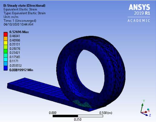
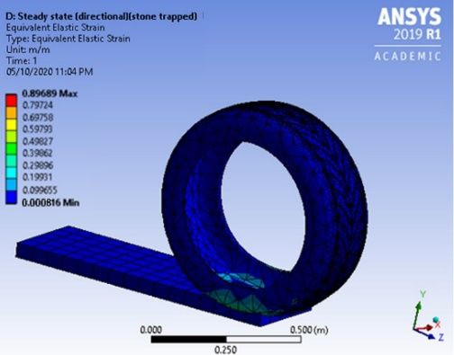
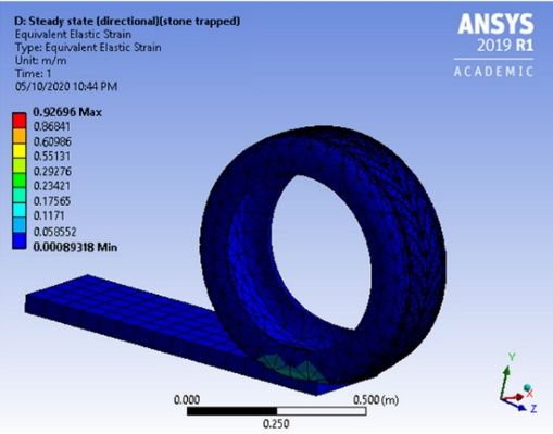
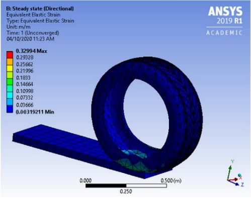
MATEC Web of Conferences 335, 03003 (2021) https://doi.org/10.1051/matecconf/202133503003
14th EURECA 2020

 terms of total deformation and Von-Mises stress were found to be the lowest for this tread
 pattern. In addition, the directional tread pattern also contributes to the lowest maximum
 Von-Mises stress for both non stone trapped and stone trapped despite of any material
 applied.

 3.2 Analysis of steady state rolling
 Steady state rolling analysis was performed in relation to determine the wear and tear of the
 tire. In this study, the equivalent elastic strain was evaluated where Fig. 8 and Fig. 9
 demonstrates the result obtained for this analysis.

 (a) (b)
 Fig. 8. Equivalent elastic strain of non-stone trapped directional tire on (a) dry road and (b) wet road.

 (a) (b)
 Fig. 9. Equivalent elastic strain of stone trapped directional tire on (a) dry road and (b) wet road.

 According to Fig. 8 and Fig. 9, steady state rolling analysis was performed on a directional
 tread pattern, it is observed that the equivalent elastic strain is lower on a wet road for both
 cases of stone trapped and non-stone trapped. In contrast, the equivalent elastic strain reaches
 to a greater value on a dry road for both cases. In general, it is understood that the dry road
 surface would generate more friction than the wet road surface and hence tire wear will be
 greater on a dry road [18]. Farroni et al. [19] had also expressed that a dry road would results
 in a difficulty for the tire rubber to slip over the road surface which in turns leads to heat
 build-up in the tire. This eventually increase the tire wear and tear due to an increase of tire
 temperature. Apart from that, it can also be seen that the value of equivalent elastic strain
 doubled in the case where there is stone trapped as to compared with the non-stone trapped.

 9
MATEC Web of Conferences 335, 03003 (2021) https://doi.org/10.1051/matecconf/202133503003
14th EURECA 2020

 Table 7. Maximum equivalent elastic strain of tire tread pattern.
 Non stone trapped Stone trapped
 Maximum Equivalent Elastic Maximum Equivalent Elastic
 Type of tread
 Strain, m/m Strain, m/m
 pattern
 Dry road, Wet road, Dry road, Wet road,
 µ=0.7 µ=0.4 µ=0.7 µ=0.4
 Symmetrical 8.2971e-4 3.7354e-5 3.5229e-3 8.3142e-4
 Asymmetrical 1.6882e-4 1.6793e-5 4.7392e-3 9.5219e -4
 Directional 0.5270 0.3299 0.9270 0.8969

 Similarly, the results obtained for the 2 other tread patterns which are the symmetrical
 and asymmetrical also shows that the maximum equivalent elastic strain is greater for the
 case where there is stone trapped and on a dry road condition (Table 7). For the case of non-
 stone trapped, the symmetrical tread pattern shows the lowest value of maximum equivalent
 elastic strain followed by the asymmetrical and directional. As for the case of stone trapped,
 the asymmetrical tread pattern results in the lowest value of maximum equivalent elastic
 strain followed by the symmetrical and directional.

 Fig. 11. Maximum equivalent elastic strain against time for directional tread pattern.

 From the Fig. 11, it is observed that a good fit graph is obtained where the equivalent
 elastic strain increases linearly with the time interval for both cases of non-stone trapped and
 stone trapped. Like a previous study performed by Singhal et al. [9], a close range of
 equivalent elastic strain value was observed similarly to the results obtained in Table 8 for
 the non-stone trapped case whereby a good fit graph was also obtained.
 All in all, it can be deduced that the stone trapping in tire tread pattern would have an
 impact on the lifespan of the tire. This is observed when there is a significant increase of the
 maximum equivalent elastic strain value for all type of tread patterns in the case of stone
 trapped as it compared to non-stone trapped. Furthermore, it can be also be deduced that the
 symmetrical tread pattern design is the most ideal for this case since it provides the least wear
 and tear for both dry and wet road condition. This tread pattern was found to have the lowest
 increment of maximum equivalent elastic strain from the case of non-stone trapped to stone
 trapped in both road condition.

 10
MATEC Web of Conferences 335, 03003 (2021) https://doi.org/10.1051/matecconf/202133503003
14th EURECA 2020

 4 Conclusion

 To summarise, this study highlights the stone trapping mechanism on commercial road
 tires and further emphasizes on what critical effect it has on them. In this case, this research
 paper analyses and compare the performance in terms of tire’s behaviour and wear rate
 between both stone trapped and non-stone trapped tires. The parameters considered in this
 study includes the type of common commercial tires used in Malaysia (symmetrical,
 asymmetrical, directional), tire specifications, type of rubber material, inflation pressure,
 road condition (wet, dry), groove depth and size of stones. Both CAD modelling and
 simulation processes are completed using SolidWorks, Fusion360 and ANSYS 19.1 software
 respectively.
 The results obtained from the tire inflation analysis shows that there is a significant
 increase in the tire’s stresses and total deformation when there is stone trapped. It was also
 found that the directional tread design shows the least effect on the stone trapping mechanism
 since it contributes to the lowest maximum Von-Mises stress for both non stone trapped and
 stone trapped despite of any material applied.
 The results obtained from the steady state rolling analysis indicates that tire’s wear is
 higher when there is stone trapped specifically on a dry road surface as to compared to stone
 trapped on a wet road surface. Through this analysis, it was found that the symmetrical tread
 pattern design provides the least wear and tear since it has the lowest increment of maximum
 equivalent elastic strain from the case of non-stone trapped to stone trapped in both road
 condition.
 All in all, this study aims to provide an insight on how stone trapping in tire tread could
 have an influence on the safety of road users and lifespan of the tire through the results
 obtained. Apart from that, this study also pursues to aid in contributing on further analysis
 particularly in the scope of optimizing the design of tire in any future study.
 For future works relating to this study, experimental method can be involved to prove or
 validate the results and hypotheses of this novel study. Additional parameters like different
 moving average speed and other type of road conditions such as muddy or winter road surface
 should also be taken into consideration in this study to provide a deeper insight on this topic.
 Furthermore, explicit dynamic analysis can also be conducted to determine the harmonic
 response of the tire under stone trapping for the given boundary conditions. This can further
 help to optimize the tire tread pattern towards obtaining the best fit design to overcome or to
 reduce negative impact of stone trapping on the tire performance.

 This work is supported by Taylor’s School of Computer Science and Engineering for providing
 sufficient resources and tools.

 References
 1. Continental Tires. (27 April 2020). Tire damages. Available: https://www.continental-
 tires.com/car/tire-knowledge/tire-damage-age-repair/tire-damages.
 2. Bridgestone. (28 April 2020). Tire Tread Patterns. Available:
 https://www.bridgestonetire.com/tread-and-trend/tire-talk/tire-tread-patterns
 3. R. Muniandy, D. Moazami, H. Hamid, S. Hassim, "Characterization of effective tire
 contact area for various tread patterns," Instrum. Sci. Technol., 42, pp. 15-26 (2014)
 4. T. F. Fwa, S. S. Kumar, K. Anupam, G. P. Ong, "Effectiveness of tire-tread patterns in
 reducing the risk of hydroplaning," Transp. Res. Rec., 2094, pp. 91-102 (2009)
 5. S. S. Kumar, K. Anupam, T. Scarpas, C. Kasbergen, "Study of hydroplaning risk on
 rolling and sliding passenger car," Procedia Soc. Behav. Sci., 53, pp. 1019-1027 (2012)

 11
MATEC Web of Conferences 335, 03003 (2021) https://doi.org/10.1051/matecconf/202133503003
14th EURECA 2020

 6. R. Sreeraj, V. Sandeep, R. Gokul, P. Baskar, "Tire wear analysis using ABAQUS," Int
 J Innov Res Sci Eng Technol, 5, pp. 14403-14410 (2016)
 7. J. Chang, H. Chenyuan, J. Xiaoxiong, "FE simulation of tire wear with complicated
 tread pattern," Procedia Engineering, 15, pp. 5015-5019 (2011)
 8. A. Leyland, A. Matthews, "On the significance of the H/E ratio in wear control: a
 nanocomposite coating approach to optimised tribological behaviour," Wear, 246, pp.
 1-11 (2000)
 9. A. Singhal, M. S. Khidiya, D. Gautam, S. Meena, K. Gahlot, "Analysis of a tyre on
 different treads at same pressure and load under static conditions," Int. J. Sci. Res. Sci.
 Eng. Technol., 2, pp. 653-657 (2016)
 10. J. Wu, Y. S. Wang, B. L. Su, Q. Liu, "Experimental and numerical studies on tire tread
 block friction characteristics based on a new test device," Adv. Mater. Sci. Eng., 2014,
 p. 816204 (2014)
 11. E. Madenci, I. Guven, The finite element method and applications in engineering using
 ANSYS® (Springer, 2015)
 12. K. Gok, S. Inal, A. Gok, E. Gulbandilar, "Comparison of effects of different screw
 materials in the triangle fixation of femoral neck fractures," J. Mater. Sci. Mater. Med.,
 28, p. 81 (2017)
 13. B. N. J. Persson, U. Tartaglino, O. Albohr, E. Tosatti, "Rubber friction on wet and dry
 road surfaces: The sealing effect," Phys. Rev. B, 71, p. 035428 (2005)
 14. C. Ihueze, C. O. Mgbemena, A. Menon, "2D static failure prediction for critical stresses
 of an Automobile Tire Side Walls using MATLAB PDE Toolbox," IOSR Journal of
 Mechanical and Civil Engineering, 11, pp. 70-76 (2014)
 15. L. Spiegel, G. F. Limbrunner, Instructor's manual to accompany applied statics and
 strength of materials, fourth edition (Prentice Hall, 2004)
 16. C. O. Mgbemena, T. E. Boye, I. Emovon, "Static analysis of a tire sidewall developed
 from tailored Organomodified Kaolin/Natural Rubber Vulcanizates," J. Adv. Eng.
 Comput., 1, pp. 106-113 (2017)
 17. N. B. Dhokey, K. K. Rane, "Wear behavior and its correlation with mechanical
 properties of TiB2 reinforced aluminium-based composites," Adv. Tribol., 2011, p.
 837469 (2011)
 18. B. Ma, H.-g. Xu, Y. Chen, M.-y. Lin, "Evaluating the tire wear quantity and differences
 based on vehicle and road coupling method," Adv. Mech. Eng., 9(5), p.
 1687814017700063 (2017)
 19. F. Farroni, R. Russo, F. Timpone, "Experimental investigations on rubber friction
 coefficient dependence on visco-elastic characteristics, track roughness, contact force,
 and slide velocity," Tire Sci. Technol., 45, pp. 3-24 (2017)

 12
You can also read