Installation and operating instructions for Brake HS 165 FHM E 09.778e
←
→
Page content transcription
If your browser does not render page correctly, please read the page content below
Installation and operating instructions for
                                            Brake HS 165 FHM

                                                         E 09.778e

Schaberweg 30-38    Phone +49 6172 275 0   www.ringspann.com
61348 Bad Homburg   Fax +49 6172 275 275   info@ringspann.com
Germany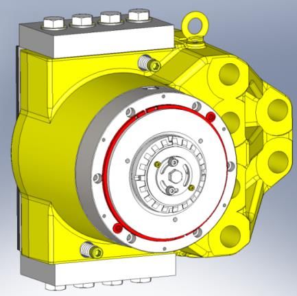
Installation and operating instructions for
                              Brake HS 165 FHM spring activated –                    E 09.778e
                                       hydraulically released
Issue: 12.02.2021        Version: 2                   Drawn: BAHS    Checked: EISF   Pages: 30    Page: 2

Important
Please read these instructions carefully before installing and operating the product. Your particular
attention is drawn to the notes on safety.
These installation and operating instructions are valid on condition that the product meets the
selection criteria for its proper use. Selection and design of the product is not the subject of these
installation and operating instructions.
Disregarding or misinterpreting these installation and operating instructions invalidates any product
liability or guarantee by RINGSPANN; the same applies if the product is taken apart or changed.
These installation and operating instructions should be kept in a safe place and should accompany
the product if it is passed on to others -either on its own or as part of a machine- to make it
accessible to the user.

Safety Notice
•   Installation and operation of this product should only be carried out by skilled personnel.
•   Repairs may only be carried out by the manufacturer or accredited RINGSPANN agents.
•   If a malfunction is indicated, the product or the machine into which it is installed, should be
    stopped immediately and either RINGSPANN or an accredited RINGSPANN agent should be
    informed.
•   Switch off the power supply before commencing work on electrical components.
•   Rotating machine elements must be protected by the purchaser to prevent accidental contact.
•   Supplies abroad are subject to the safety laws prevailing in those countries.

    This is a translation of the German original version!
    In case of inconsistencies between the German and English version of this
    installation and operating instruction, the German version shall prevail.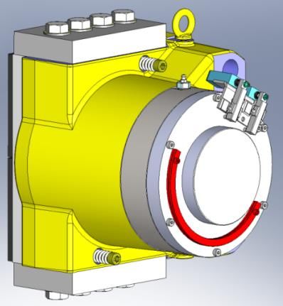
Installation and operating instructions for
                                Brake HS 165 FHM spring activated –              E 09.778e
                                         hydraulically released
Issue: 12.02.2021          Version: 2              Drawn: BAHS   Checked: EISF   Pages: 30   Page: 3

Contents

1   DESCRIPTION OF THE CALIPER
    1.1 Principle
    1.2 Delivery condition
2 INSTALLATION
    2.1 Preparing the positioning area
    2.2 Installing the disc
    2.3 Installing the caliper
    2.4 Initial start-up
3 OPERATIONAL RUNNING
    3.1 Caliper tightening
    3.2 Caliper untightening
    3.3 Caliper manual release
4 PERIODIC MAINTENANCE
5 MAINTENANCE
    5.1 Manual release: activation
    5.2 Manual release: deactivation
    5.3 Adjustment of brake pad clearance, pad wear take up
    5.4 Replacement of worn brake pads
    5.5 Opening and wear contacts (mechanicals) adjustment
6 SPARE PARTS
7 TROUBLESHOOTING
Installation and operating instructions for
Brake HS 165 FHM spring activated – E 09.778e
hydraulically released
Issue: 12.02.2021 Version: 2 Drawn: BAHS Checked: EISF Pages: 30 Page: 4
1 Description of the caliper
1.1 Principle
The HS 165 FHM calipers are hydraulic fail-safe calipers; the braking force is applied by spring
washers and hydraulic pressure is necessary to hold the brake released. The stack of spring
washers is adjusted in factory. This adjustment, combined with adjustment of the pads gap,
determines the braking torque value.
There is a type plate on the brake with a 16-digit article number. The exact design of the brake is
defined by this article number only.
As well as these instructions, please also consider the catalogue data for the brake at
www.ringspann.com and the drawings in the individual sections.
The Caliper is describe as “manually readjusted”. This means that the pad wear must be
compensated for by manual adjustment of the pad gap to avoid any loss of braking force.
The brakes have a manual release device mechanically holding the caliper open, without any
need for a hydraulic pressure. This release is useful for installation and maintenance work when
there is no hydraulic pressure available.
1.2 Delivery condition
The caliper is delivered in the following conditions:
- In manual release position, i.e. manually locked in open position,
- With pads installed,
- Adjusted with the nominal lining gap,
- The holding force adjusted according to customer’s specifications,
- Mechanical contacts adjusted,
- With bleed screw in correct position.
- As well as these instructions, please also consider the catalogue data for the brake at
www.RINGSPANN.de and the drawings in the individual sections.Installation and operating instructions for
Brake HS 165 FHM spring activated – E 09.778e
hydraulically released
Issue: 12.02.2021 Version: 2 Drawn: BAHS Checked: EISF Pages: 30 Page: 5
Life-threatening danger!
Disc must be absolutely degreased before all contact with the brakes
linings.
In case of lining pollution with grease, the nominal brake force is not
guaranteed.
Calipers are fail safe components.
All setting and repairs must be performed by skilled operators.
BE CAREFUL: The caliper is delivered in " manual release" position and
the holding force is adjusted in the factory.
Instructions in this manual must be followed up to chapter 2.4 inclusive
(INITIAL START-UP) to ensure that the brake is operational.
When assembling, operating and maintaining the brake it is to be
ensured that the entire drive train is secured against being switched on
unintentionally. Moving parts can cause severe injury. Rotating parts
(e.g. brake disc) must be secured by the operator against unintentional
touching.
Strongly pre-loaded pressure springs are installed in the springed
thrusters of the brake. The spring thruster may only be disassembled by
the factory.
2 Installation
2.1 Preparing the positioning area
Ensure that the positioning surface is clean and dry.
Make sure that there is sufficient space around the brake.
Check that the mounting holes are in conformity (center distances, sizes and numbers).Installation and operating instructions for
Brake HS 165 FHM spring activated – E 09.778e
hydraulically released
Issue: 12.02.2021 Version: 2 Drawn: BAHS Checked: EISF Pages: 30 Page: 6
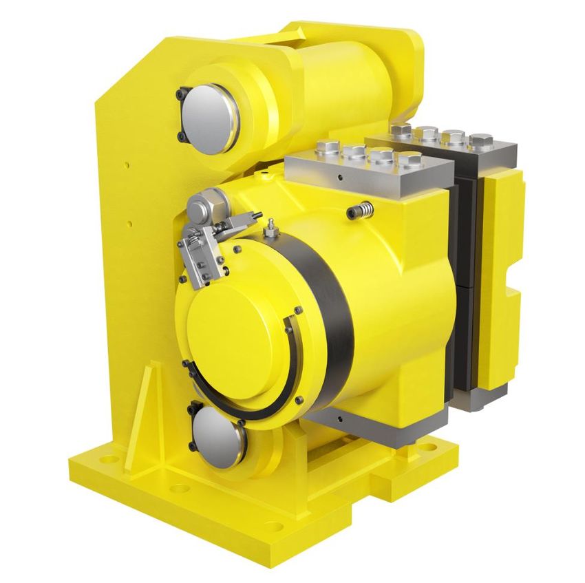
Brake HS 165 FHM-420 L-H (Thrustor mounted left shown)
Fig. 2.1Installation and operating instructions for
Brake HS 165 FHM spring activated – E 09.778e
hydraulically released
Issue: 12.02.2021 Version: 2 Drawn: BAHS Checked: EISF Pages: 30 Page: 7
Brake HS 165 FHM-420 R-V
Fig. 2.2
2.2 Installing the disc
Make sure that the disc is accurately positioned and attach it to its hub.
Check that the disc is not buckled more than 0.3mm.
Check that the disc is 30mm thick standard arrangement.
Important!
If these conditions are not complied with, the caliper cannot be
assembled or will not operate to standard. Contact RINGSPANN
for more details.Installation and operating instructions for
Brake HS 165 FHM spring activated – E 09.778e
hydraulically released
Issue: 12.02.2021 Version: 2 Drawn: BAHS Checked: EISF Pages: 30 Page: 8
First clean the disc tracks with the degreasing agent:
- Quick drying degreaser (CRC / KF)
Important!
BE CAREFUL: The disc must be degreased and free of any deposits so
as not to decrease the friction coefficient.
2.3 Installing the caliper
2.3.1 List of tools
1. 1200Nm torque wrench, socket measuring 46mm across flats (caliper attachment).
2. 8mm AF spanner + Flexible pipe inside Ø6mm (Bleed).
2.3.2 Brake handling
Put the assembly in position on the disc, raising it with lifting ring 1 Fig. 2.3.
Weight for one caliper: HS 165 FHM-___ H = 625kg HS 165 FHM-___ R-V = 528kg
2.3.3 Alignment procedure
1. Brake HS 165 FHM-420 R-V Check the disc position 257,5 +/-9 mm Fig. 2.2 use the
balancing screw (16mm on flats) and that the disc is parallel // 0,3 to the brake pad. Check
that the support balance in relation to the disc is less than 0,2mm. Check that the disc is fully
between the pads.
2. Brake HS 165 FHM-420 H check the disc position 8mm mini fixed pad side 2a; 18mm mini
from the other side 2b Fig. 2.3.Installation and operating instructions for
Brake HS 165 FHM spring activated – E 09.778e
hydraulically released
Issue: 12.02.2021 Version: 2 Drawn: BAHS Checked: EISF Pages: 30 Page: 9
A crowbar can be used in the area shown by the arrow 2a and 2b to slide the caliper from one
side to the other.
Fig. 2.3Installation and operating instructions for
Brake HS 165 FHM spring activated – E 09.778e
hydraulically released
Issue: 12.02.2021 Version: 2 Drawn: BAHS Checked: EISF Pages: 30 Page: 10
Check that disc deflection in relation to the support does not exceed 0.3mm.
Check parallelism of the fixed pad 3 Fig. 2.4 in relation to the disc using a set of laminated shims,
in compliance with the following spacing:
Transversal spacing: 0.2mm maxi. over pad width.
Fig. 2.4
Longitudinal spacing: 0.3mm max. over pad length. If necessary, set the support using foil 4
located close to the attachment screws Fig. 2.4.Installation and operating instructions for
Brake HS 165 FHM spring activated – E 09.778e
hydraulically released
Issue: 12.02.2021 Version: 2 Drawn: BAHS Checked: EISF Pages: 30 Page: 11
3. Position the screws M30 class 8.8 for caliper to the basement connection.
The tightening torque (Cs) which has to be applied on the screws M30 class 8.8 rows for each
nut is: Cs = 1200Nm ±10% with greased screws.
Brake HS 165 FHM-420 R-V 8 screws M30 class 8.8
Brake HS 165 FHM-420 L(R)-H 6 screws M30 class 8.8
Important!
Check the tightening torque
4. Check, after having tightened to torque, that the whole part has not moved.
2.3.4 Orientation of the piston heads
If the caliper stands on a horizontal support, the orientation of the piston heads is not important.
For other positions, the piston heads must be oriented: Bleed screw 11271-17 on top Fig. 2.3
and connecting plug on bottom, in a vertical plan 30°. For more information, please contact
RINGSPANN.
2.3.5 Hydraulic connection
Important!
MAX PRESSURE: 250bar
For an ambient temperature range from 0 through 60°C, recommended oil is ISO HM32. By
instance, RINGSPANN uses FUCHS RENOLIN EXTRA 32S.
Use a mineral oil with a viscosity range between 10 and 380mm²/s (optimal range between 12
and 100mm²/s) while allowing for the ambient temperature conditions
Important!
This oil must be clean
(maximum permitted level of pollution as per NAS 1638: 10µm).
Use only new fluid and never mix several types all brands of fluid.Installation and operating instructions for
Brake HS 165 FHM spring activated – E 09.778e
hydraulically released
Issue: 12.02.2021 Version: 2 Drawn: BAHS Checked: EISF Pages: 30 Page: 12
The caliper must be connected to its source at a hydraulic pressure 250bar max,
by threaded plug G 3/8’’. Fig. 2.5.
Do not use hemp, mastic, Teflon (etc.) and use flexible hoses exclusively.
It is preferable to use liquid joints.
Clean the pipes and couplings while ensuring that they are perfectly clean
(soiling, scale, swarf, etc.).
Fig. 2.5
2.3.6 Electrical connection
Opening and wear contact:
Bipolar switch "O + F" snap action
Mechanical contact output by
cable 5 wire x 0.75mm²
Standard length of the cable: 2m.
Fig. 2.6Installation and operating instructions for
Brake HS 165 FHM spring activated – E 09.778e
hydraulically released
Issue: 12.02.2021 Version: 2 Drawn: BAHS Checked: EISF Pages: 30 Page: 13
2.4 Initial start-up
2.4.1 Hydraulic circuit bleed
Tools: Spanner, 8mm across flats, 6mm ID flexible hose.
Important!
Take the necessary precautions to avoid the oil being sprayed onto the
disc.
1. Connect the bleed screw 11271-17 to a 6mm ID flexible hose and put the end of the hose
into a container Fig. 2.7.
2. Feed oil to the caliper from the power pack, then from the hand pump.
3. Loosen slightly the bleed screw 11271-17.
4. When the oil pours out continuously and there are no more air bubbles at the end of the
hose, tighten the bleed screw 11271-17.
5. Disconnect the flexible hose (beware of any oil remaining in the hose)
Important!
This file must be clean
(maximum permitted level of pollution as per NAS 1638: 10µm).
Use only new fluid and never mix several types all brands of fluid.Installation and operating instructions for
Brake HS 165 FHM spring activated – E 09.778e
hydraulically released
Issue: 12.02.2021 Version: 2 Drawn: BAHS Checked: EISF Pages: 30 Page: 14
Fig. 2.7Installation and operating instructions for
Brake HS 165 FHM spring activated – E 09.778e
hydraulically released
Issue: 12.02.2021 Version: 2 Drawn: BAHS Checked: EISF Pages: 30 Page: 15
2.4.2 Deactivate the manual release
The principle is to position the stopping rings in the piston groove once the pressure is applied.
They are fixed in position by 2 screws Fig. 2.8.
When the caliper is in operating mode, the rings are screwed to the cover in holding position.
Manual release in place Manual release pending
Fig. 2.8
Refer to chapter 5.2 for more information about the manual release mode
Important!
The manual release must be deactivated to ensure a well running of the
brake.
2.4.3 Adjustments of pad gap
Important!
Contact are factory set and do not need any adjustment.
If necesary, follow the procedure chapter 5.3
First check the thickness of the disc. Use a set of
laminated shims to verify that total gap between
the pads and the disc is equal to the “X” gap.
The gap must be equal both side (a=b)
Fig.2.9Installation and operating instructions for
Brake HS 165 FHM spring activated – E 09.778e
hydraulically released
Issue: 12.02.2021 Version: 2 Drawn: BAHS Checked: EISF Pages: 30 Page: 16
2.4.4 Control of the general running
Important!
Be Careful: The disc must be degreased and free from any deposits so as
not to decrease the friction coefficient.
Check the well running of the electric contacts.
Run the brake under no-load with the disc turning, 20 or so times, to bed in the pads.
Information!
THE SYSTEM IS NOW OPERATIONAL
3 Operational RUNNING
3.1 Caliper tightening
The lack of hydraulic pressure allows the pads to be tightened on the disc.
The opening contact is not activated.
3.2 Caliper untightening
Apply a minimum pressure of 230bar to release the brake.
The opening contact is activated.
3.3 Caliper manual release
Manual release keeps the caliper open without hydraulic pressure.
Refer to chapter 5.1 and chapter 5.2.Installation and operating instructions for
Brake HS 165 FHM spring activated – E 09.778e
hydraulically released
Issue: 12.02.2021 Version: 2 Drawn: BAHS Checked: EISF Pages: 30 Page: 17
4 PERIODIC MAINTENANCE
Every two months, check:
- As a general rule, inspect the entire system for correct operation
- Check that there is not any leakage
- Also, check the brake pad gap see chapter 5.3.
Attention!
When the remaining lining thickness reaches 3mm, proceed to pad
exchange as per chapter 5.4. If this rule is not observed, a loss of
breaking force may occur.
Every two years, replace:
- Oil in the power pack (refer to the power pack instructions)
Every five years:
- Plan complete overhaul of the entire unit (replace worn parts, seals, spring washers, flexible
hoses…)
5 Maintenance
5.1 Manual release: activation
1. Supply the caliper with a pressure of 230 bar and maintain the pressure until point 6.
2. Remove the 2 retaining segments 14 by their 2 screws V03 on the cover 21.
3. Remove the cover 21 via its 6 Allen screws V09.
4. For an easier handling, it is possible the remove the connector of indicator switches
Fig.5.1. Unlock the connector by insert the screwdriver behind the connector and turn it a
1/4 of a turn counter-clockwise and then insert the screwdriver into the slot at the side to
release the connector.
In ‘ATEX’ execution, it is not possible to remove the connector
Screwdriver
Slot
Fig. 5.1Installation and operating instructions for
Brake HS 165 FHM spring activated – E 09.778e
hydraulically released
Issue: 12.02.2021 Version: 2 Drawn: BAHS Checked: EISF Pages: 30 Page: 18
5. Put the 2 retaining segments 14 in the piston groove 04 Fig. 5.2.
6. Screw the 2 screws V03 into the unlock position to securely hold the retaining segments.
7. Cut off the pressure.
8. Remove the 2 screws V03 to put them on the cover 21
9. Replace the cover 21 and tighten the 6 screws V09.
10. Re-engage the connectors in the switches and lock with the flat screwdriver by a 1/4 of a
turn clockwise.
Attention!
MOVEMENT IS STILL POSSIBLE AFTER CUTTING OFF THE PRESSURE.
04
V03 in standby V03 in release 14
position V09 21 position
Fig. 5.2Installation and operating instructions for
Brake HS 165 FHM spring activated – E 09.778e
hydraulically released
Issue: 12.02.2021 Version: 2 Drawn: BAHS Checked: EISF Pages: 30 Page: 19
5.2 Manual release: deactivation
1. With the pressure cut off, remove the cover 21 with its 6 Allen screws V09 (5mm male key).
V03 in standby V09 21 V03 in release position 14
position
Fig. 5.3
2. For an easier handling, it is possible the remove the connector of indicator switches Fig. 5.1.
Unlock the connector by insert the screwdriver behind the connector and turn it a 1/4 of a turn
counter-clockwise and then insert the screwdriver into the slot at the side to release the
connector. In ‘ATEX’ execution, it is not possible to remove the connector see Fig. 5.1.
3. Supply the caliper with a pressure of 230bar and maintain it throughout the operation.
Attention!
Retaining segments 14 can be fall. Do not cutting off the pressure without
removed these retaining segment.
4. Remove the 2 retaining segments 14 Fig. 5.2 and install them in the standby position on the
cover 21, one on the other, using the 2 screws V03. See Fig.5.3.
5. Reinstall cover 21 and retighten 6 screws V09 Fig.5.2 chapter 5.1.
6. Reengage connectors in the switches and lock it using screwdriver turn it to 1/4 turn
clockwise.Installation and operating instructions for
Brake HS 165 FHM spring activated – E 09.778e
hydraulically released
Issue: 12.02.2021 Version: 2 Drawn: BAHS Checked: EISF Pages: 30 Page: 20
5.3 Adjustment of brake pad clearance, pad wear take up
Danger!
Frequently check the total gap between pads and the disc.
(a 1mm increase to this gap corresponds to 8% loss of torque).
Refer to the RINGSPANN Datasheet for the nominal clearance.
Attention!
When the remaining lining thickness reaches 3mm, proceed to pad
exchange as per chapter 5.4. If this rule is not observed, a loss of
breaking force may occur.
Tools: 19mm AF spanner - 5mm Allen wrench screwdriver
Procedure:
1. Apply a 230bar hydraulic pressure to the caliper and maintain the pressure throughout the
entire procedure.
Attention!
DO NOT USE THE MANUAL RELEASE DEVICE
2. Remove the cover 21 by its 6 screws V09 Fig.5.2.
3. Remove the 2 connectors of opening and wear contacts Fig.5.1.
4. Unscrew and remove the 2 screws V04 (5mm Allen wrench) and 2 washers V14 Fig.5.4.
5. Remove the locking washer 15 to free the wear take up screw 06 Fig.5.4.
6. Screw or unscrew using a flat spanner Fig.5.5 or a 19mm socket, the adjuster screw 06 until
the gap between the pad and the disc reaches the required value.Installation and operating instructions for
Brake HS 165 FHM spring activated – E 09.778e
hydraulically released
Issue: 12.02.2021 Version: 2 Drawn: BAHS Checked: EISF Pages: 30 Page: 21
06
15
V14
V04
Fig. 5.4
7. Reposition the lock washer 15 each side and secure with screws V04 and washers V14.
8. Replace the cover 21 with the 6 screws V09 and the connectors of switches.
9. Be careful not to reverse the assignment of the connectors on the two switches.
Attention!
Be careful not to reverse the assignment of the connectors on the two
switches.Installation and operating instructions for
Brake HS 165 FHM spring activated – E 09.778e
hydraulically released
Issue: 12.02.2021 Version: 2 Drawn: BAHS Checked: EISF Pages: 30 Page: 22
Fig. 5.5
5.4 Replacement of worn brake pads
Tools: 30mm AF spanner - 19mm AF spanner key - 5mm Allen wrench – 10mm AF wrench.
Procedure: For fixed pad side
1. Put the caliper into manual release position, see chapter 5.1 and switch off the pressure.
2. Cover being removed, unscrew and remove the allen screws V04 and washers V14 Fig. 5.4
see chapter 5.3
3. Remove the locking washer 15 to free the wear take up screw 06 Fig. 5.4 see chapter 5.3.
4. Screw or unscrew using a 19mm wrench or socket the wear take up screw 06 until the gap
between the pad and the disc enables to put the new pad in position Fig.5.5 see chapter
5.3.
5. Screw a M10x40 min. screw in the retaining plate 09 on the pad extraction side to handle it.
6. Remove [1 reatining plate 09 + 4 screws V08 + 4 washers V17] on the side where the pad
is to be removed.
7. Loosen 2 screws V07 pad holding.Installation and operating instructions for
Brake HS 165 FHM spring activated – E 09.778e
hydraulically released
Issue: 12.02.2021 Version: 2 Drawn: BAHS Checked: EISF Pages: 30 Page: 23
8. Fit a screw M10 V30 into the end of the pad 11 to facilitate gripping. (recommended length:
60 mm).
9. Remove pad 11 from its pad holder 01 by pulling screw M10
10. Fit the new pad 11 in its housing. If necessary, use the screw M10 to helps.
11. Loosen the screw M10 V30
12. Reinstall retaining plate 09 onto 01 with 4 screw V08 and washer V17.
13. Loosen the screw M10 into the retaining plate 09
Tightening torque: Cs = 470Nm ±10%+ Loctite 243.
Note: Check that the 4 screws V18 located on the opposite side are correctly torqued to
470Nm.
Fig. 5.6Installation and operating instructions for
Brake HS 165 FHM spring activated – E 09.778e
hydraulically released
Issue: 12.02.2021 Version: 2 Drawn: BAHS Checked: EISF Pages: 30 Page: 24
Procedure: For the other side
1. Fit a screw M10 into the stop plate 10 to facilitate gripping.
2. Remove [1 reatining plate 10 + 4 screws V08 + 4 washers V17] on the side where the pad
is to be removed.
3. Fit a screw M10 V30 into the end of the pad 11 to facilitate gripping (recommended length:
60mm).
4. Remove screw V10 including the pad pull-back spring.
5. Remove pad 11 from its pad holder 02 by pulling screw M10.
6. Fit the new pad 11 in its housing. If necessary, use the screw M10.
7. Loosen the screw M10 V30.
8. Put back in place the screw V10 including its spring and tighten it up fully on the pad.
9. Reinstall retaining plate 10 onto 02 with 4 screws V08 and Washer V17.
10. Loosen the screw M10 into the stop plate 10.
11. After the pads replacement, remove the manual release chapter 5.2 und proceed with the
adjustment of the pad gap chapter 5.3
Tightening torque: Cs = 470Nm ±10%+ Loctite 243.
Note: Check that the 4 screws V18 located on the opposite side are correctly torqued to 470Nm.Installation and operating instructions for
Brake HS 165 FHM spring activated – E 09.778e
hydraulically released
Issue: 12.02.2021 Version: 2 Drawn: BAHS Checked: EISF Pages: 30 Page: 25
Fig. 5.7Installation and operating instructions for
Brake HS 165 FHM spring activated – E 09.778e
hydraulically released
Issue: 12.02.2021 Version: 2 Drawn: BAHS Checked: EISF Pages: 30 Page: 26
5.5 Opening and wear contacts (mechanicals) adjustment
Information!
Contacts are factory set and do not need any adjustment.
If necessary, follow this procedure.
Verify the gap for the pad at each caliper, otherwise perform all the operations in chapter 5.3.
Refer to the identification plate for the nominal clearance.
Tools: 2.5mm Allen wrench - 8mm AF spanner.
Wear contact
Opening contact
Fig. 5.7
5.5.1 Adjustment of ‘brake released’ switch
This switch monitors the status of the brake (closed or released)
It closes when the brake is released (set under pressure).
- Power the brake at 230 bar.
- Unscrew nut V11 (8mm on flats).
- Check that the axle 22 is in contact onto lever 41.
- Adjust the screw HC V02 (2.5mm Allen wrench) until the activation of contact. Check that state
contact is "Open".Installation and operating instructions for
Brake HS 165 FHM spring activated – E 09.778e
hydraulically released
Issue: 12.02.2021 Version: 2 Drawn: BAHS Checked: EISF Pages: 30 Page: 27
- Release pressure. When the brake is close, check the contact state (Position "closed"). If this
information is not obtained, unscrew the screw HC V02 until change of state.
- Power the brake at 230bar.
- Check that state contact is "Open". Execute this operation till correct monitoring of the" open &
closed" status.
- After an adjustment is finished, do not forget to retighten nut V11 (8mm on flats) to the screw
V02.
Fig. 5.8Installation and operating instructions for
Brake HS 165 FHM spring activated – E 09.778e
hydraulically released
Issue: 12.02.2021 Version: 2 Drawn: BAHS Checked: EISF Pages: 30 Page: 28
5.5.2 Adjustment of ‘pad wear’ switch
This switch is permanently closed and opens when the pad wear reaches 1mm.
- Power the brake at 230 bar.
- Check that the pads clearance is correctly adjusted, otherwise proceed to adjustment.
- Brake being open, check that the connection pin 22 is in contact onto lever 42.
- Release pressure to close the brake.
- Unscrew nut V11 (8mm on flats) then adjust screw HC V02 (2.5mm Allen wrench) to free it
from the switch end (adjust the screw skimming the lever).
- Adjust the screw HC V02 until the switch triggers (status « worn pads »). When the pads will
reach a 1mm wear, the switch will release (as the hysteresis of the switch is 1mm).
- After an adjustment is finished, do not forget to
retighten nut V11 (8 mm on flats) on the screw V02.
Fig. 5.9Installation and operating instructions for
Brake HS 165 FHM spring activated – E 09.778e
hydraulically released
Issue: 12.02.2021 Version: 2 Drawn: BAHS Checked: EISF Pages: 30 Page: 29
6 Spare parts
Monitoring switches (Opening/wearing) Ref.: CONOUVREG-PIN-HW
- Set of pads:
2 pads 12214-008 Ref: JG ST5 RINGSPANN 132
- Hydraulic control parts comprising (Refer to assembly drawing):
1 Piston 12660-026
1 Piston rod JOITIG-090 105 Z
1 Piston seal JOIPIS-200 184 E
1 Static piston seal JOISTA-95.6-90-1
1 Cylinder 12660-005
1 Bleed screw 11271-17
In case of order, please specify:
Type, Nr. of the caliper and item Nr. of the part.
There is a type plate on the brake with a 16-digit article number. The exact design of the brake is
defined by this article number only.Installation and operating instructions for
Brake HS 165 FHM spring activated – E 09.778e
hydraulically released
Issue: 12.02.2021 Version: 2 Drawn: BAHS Checked: EISF Pages: 30 Page: 30
7 Troubleshooting
NATURE SH SHCI VERIFICATION REMEDE
The caliper ● Motor power supply Invert the 2 phases
does not ● voltage Complete according to
release ● Motor rotation direction chapter 2.4.1 bleeding
● Fluid level
Solenoid valve power
supply
● Presence of pressure Reestablish the
pressure
The caliper ● ● Sealing of the hydraulic Change the faulty
does not unit / pipes / connections element
remain / cylinder / piston
released.
Release time ● Check the flow rate of the Change the pump
too long pump and the circuit Bleed the circuit
bleed. chapter 2.4.1
Decrease in ● ● Check the pad clearance Proceed with pad
braking force clearance adjustment
chapter 5.3
● ● Check the condition of Replace the pads and
the pads and the disc clean the disc.
(wear or grease
particles).
Pads worn ● ● Perpendicularity of Readjust the caliper.
asymmetrically support with respect to
disk
● ● Adjustment of alignment Request procedure
from RINGSPANN
Abnormal ● ● Insufficient clearance Re-adjust the pads.
overheating of between the pads and the chapter 5.3
the disc during disc in released position. Re-adjust pressure at
start-up. Check that pressure is at 230bar
230bar
● ● Pad incorrectly Readjust the caliper.
assembled
The power ● Circuit sealing Rectify sealing
pack re-starts Impurities causing oil Drain and repeat
frequently leakage operations in chapter
2.3.4 and 2.4.1
The caliper ● Air may be in the circuit Bleed according to
releases and chapter 2.4.1
closes slowlyYou can also read