Theoretical and experimental substantiation of the system of removal of harmful substances during the combustion of candles in the worship hall of ...
←
→
Page content transcription
If your browser does not render page correctly, please read the page content below
E3S Web of Conferences 263, 04013 (2021)                                    https://doi.org/10.1051/e3sconf/202126304013
FORM-2021

         Theoretical and experimental substantiation of
         the system of local removal of harmful
         substances during the combustion of candles in
         the worship hall of Orthodox churches and
         cathedrals
         Alexander Eremkin1, and Inna Ponomareva2
         1Penza   State University of architecture and construction, Penza, Russia
         2Penza   State University, Penza, Russia

                       Abstract. The analysis of the features of Orthodox churches, temples and
                       cathedrals, elements of the design of the halls of worship, and their
                       preservation. The types of hazards generated during the burning of candles
                       and the parishioners and staff present are systematized. Thermal imaging
                       surveys of convective flows formed during candle combustion were carried
                       out. A technique for conducting experiments and a diagram of an
                       experimental setup for measuring the temperature and air velocity in a
                       convective jet have been developed. The diagram of the convective flow
                       structure is presented, which consists of individual jets from each candle.
                       The results of the study have been obtained, which make it possible to
                       determine the area of stable convective flow and the place of installation of
                       the exhaust hood above the candlestick, as well as the distance between the
                       burning candles and the edge of the bottom of the umbrella. A local
                       mechanical exhaust ventilation system with umbrellas has been developed
                       to trap and remove harmful substances from the worship hall and provide
                       comfortable conditions for parishioners and preserve the decoration
                       elements of the halls. The characteristics and conditions for the efficient
                       operation of the hoods in the local exhaust ventilation system and the factors
                       influencing their operation are given.

         An innovative system of local removal of harmful substances is proposed in this article on
         the basis of the conducted studies of the convective flow when burning candles over a
         candlestick in the worship hall of the Church of the Holy First Apostles Peter and Paul in
         Penza. Currently, in the regions of Russia, a large-scale reconstruction of the destroyed ones,
         the reconstruction of existing ones, the construction of new Orthodox churches, temples and
         cathedrals are being carried out (Fig. 1).

   © The Authors, published by EDP Sciences. This is an open access article distributed under the terms of the Creative
   Commons Attribution License 4.0 (http://creativecommons.org/licenses/by/4.0/).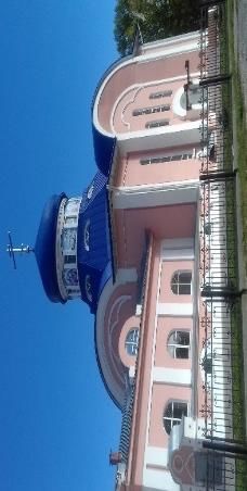
E3S Web of Conferences 263, 04013 (2021) https://doi.org/10.1051/e3sconf/202126304013
FORM-2021
а) b)
Fig. 1. General view of one of the built cathedrals in Penza: a) Spassky Cathedral; b) the Temple of the
Holy Apostles Peter and Paul
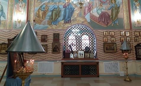
A feature of Orthodox churches, cathedrals and temples is the presence in the worship
hall of works of architecture, artistic paintings, icons, frescoes, decoration of the iconostasis,
icon case and others, which have historical and artistic value. To ensure the safety of the
design elements, high requirements are imposed on the parameters of the artificial internal
microclimate tv, φv, Vv and air purity. At the same time, it is necessary to provide
comfortable conditions for parishioners and service personnel in the worship hall, which is a
difficult task due to the harmful emissions from people, heat, moisture, carbon dioxide, and
especially during the combustion of candles - soot, soot, moisture, carbon dioxide, heat [1-
4].
It has been established that several dozen candlesticks and hundreds of burning candles
are installed in the halls of worship during the service period (Fig. 2). Burning candles on
candlesticks are also installed on ordinary days for parishioners when visiting cathedrals.
Based on the research and analysis of the movement of ventilation air flows and the natural
movement of air inside the worship hall, it was found that emitting soot and soot, due to
incomplete combustion of paraffin from candles, settle on the inner surfaces of the worship
hall, paintings, icons, paintings and on the clothes of parishioners. As a result, the decoration
of the hall over the years acquires a smoky, unsightly appearance. Other emitted hazards:
heat, moisture, carbon dioxide, negatively affect the well-being of parishioners and the
decoration of the hall [5].
Fig. 2. Demonstration shot of burning candles on different candlesticks in the worship hall of the
Church of the Holy Primate Apostles Peter and Paul
To confirm the conclusions made, experimental studies of the emission of soot and soot
when burning candles were carried out. At the same time, a specially designed in the creative
workshop of D.A. Trofimov's "Tsargrad" stand (Fig. 3).
2
E3S Web of Conferences 263, 04013 (2021)                                    https://doi.org/10.1051/e3sconf/202126304013
FORM-2021

         a)                                  4   b)                                     c)
              1
                                                                                6
                                                                                                                       1
                                                 3                             7                                       5
                                                                                    1
                                                                                                                       3
                                                                                                                       2

         Fig. 3. The scheme of the experimental stand for studying the process of soot and soot emission on the
         surfaces of the walls and the decoration of the room: 1 - room; 2 - candlesticks; 3 - candle; 4 - a shelter
         for catching soot and soot; 5 - room wall; 6 - sticker of white paper on the surface of the ceiling up to
         burning candles; 7 - soot and soot; a - scheme of the shelter above the candlestick for trapping soot and
         soot; b - removing a part of the smoked paper from the ceiling surface; c - the state of the surface of the
         room at the beginning of the burning of candles.

             Inside the room - 1 there is an imitation design of a candlestick -2 with burning candles -
         3 and a shelter - 4 for trapping soot and soot. The walls of the premises - 5 are pasted over
         with white paper - 6. Within one month, when more than 4 thousand candles were burned,
         the walls and ceiling were covered with soot and soot - 7. Such processes also occur in the
         halls of worship when candles are burned, which negatively affects the decoration and
         decoration of the premises Orthodox churches, cathedrals and temples.
             Regular repairs, refurbishment and restoration work require significant costs. To combat
         these hazards, most Orthodox churches, cathedrals and temples use energy-intensive
         ventilation and air conditioning systems in order to save money in combination with natural
         ventilation. To combat the harmful emissions from burning candles in the Church of the
         Nativity of the Most Holy Theotokos in Samara and in the Church of the Life-Giving Trinity
         in Astrakhan, a shelter was mounted above the candlesticks (Fig. 4, 5), which does not meet
         design requirements and does not ensure proper collection and soot from the hall of worship.
         There are other examples of shelters that do not have theoretical and experimental
         justification.

         Fig. 4. Shelter on a candlestick in the Church of the Life-Giving Trinity in Astrakhan.

             Despite the significant costs, the problem of creating an internal microclimate in the hall
         of worship of Orthodox churches, temples and cathedrals remains relevant and requires new
         approaches in order to catch and remove harmfulness when burning candles in the hall of
         worship. The authors propose an innovative system of the type of local exhaust mechanical
         ventilation for trapping and removing harmful substances directly in the places of their
         formation when burning candles in the worship hall of Orthodox churches, temples and
         cathedrals. At the same time, it is proposed to use traditional exhaust hoods for trapping and
         removing hazards (Fig. 5).
             For technical solutions of local exhaust ventilation, well-known (Fig. 5 a, b, c) and
         proposed by the authors of the umbrella designs (Fig. 5 d, e) are proposed.

                                                             3
E3S Web of Conferences 263, 04013 (2021)                                    https://doi.org/10.1051/e3sconf/202126304013
FORM-2021

         Fig. 5. Types of exhaust hoods above the table top of the lamps for removing the combustion products
         of candles: a - a simple umbrella; b - umbrella with a canopy; c - an umbrella with a pocket; г - umbrella
         with overturned air removal; d - effective umbrella with overturned air removal; 1 - conical part; 2 -
         skirt; 3 - exhaust air duct; 4 - conical part with rounding of the top of the umbrella; 5 - exhaust pipe; 6
         - chimney perforated under the umbrella.

             A preliminary analysis of the operation of the exhaust hood in natural conditions showed
         that its configuration, dimensions and height are set above the candlestick depend on a
         number of factors: the thermal power of the convective flow during the combustion of
         candles; the volume of air in the convective flow; the speed and temperature of the air in the
         vicinity of the hoods in the convective flow; the presence of external air movement in the
         hall of worship. Determination of the values of temperature and air velocity in the convective
         flow, necessary for the development of local exhaust ventilation, an experimental setup was
         created, shown in Fig 6 [6-8].

         Fig. 6. Diagram of the experimental setup for studying the temperature and velocity fields of the
         convective flow during the combustion of candles: 1 - coordinator; 2 - holder of the coordinator; 3 -
         hot-wire anemometer sensor; 4 - thermal imager; 5 - candlestick stand; 6 - candlestick tabletop; 7 -
         candles; 8 - icon lamp; 9 - conditional coordinate grid.

            Experimental studies of the parameters of the convective temperature flow t оС, air
         velocity Vv, m/s, air flow rate L m3/h, formed during the combustion of candles, were carried
         out in accordance with GOST 12.3.018-79 «Occupational safety standards system.
         Ventilation systems. Aerodynamic Test Methods». As a means of measuring the temperature
         and air velocity in the convective flow and at the periphery, a thermoanemometer of the TKA-
         PKM type (60) was used, a combined device. A Testo-882-4 infrared thermal imager was
         used to determine the boundary of the convective flow, the temperature inside and on the
         flow axis.
            The research was carried out in the worship hall of the Church of the Holy Apostles Peter
         and Paul in Penza using working candlesticks and natural paraffin candles, as well as a
         burning oil lamp [9-11].
            In the course of experimental research, it was found that the convective air flow from an
         open flame during the combustion of candles placed on a candlestick tabletop differs
         significantly from traditional ones. (Fig. 7).

                                                             4
E3S Web of Conferences 263, 04013 (2021)                             https://doi.org/10.1051/e3sconf/202126304013
FORM-2021

         а)                                                 b)

         Fig. 7. Thermal image of an air cylindrical convective flow from burning candles: a - shape and
         temperature of air in the convective flow; b - candlestick with burning candles.

             Analysis of the data shown in Fig. 8 allows us to conclude that all candles installed around
         the perimeter in a certain one or several rows at a distance of 3-5 cm from each other (Fig. 7,
         b) and each individual candle forms its own individual convective air flow (Fig. 8, a). In the
         considered case, the total convective air flow consists of a multitude of individual convective
         jets that do not merge into a single flow (Fig. 7, a). The air temperature on the outside of the
         cylindrical convective flow varied from 33 °C in the upper part of the flow in the jet
         expansion zone to 68.4 ° C in the candle burning zone. The air temperature value must be
         taken into account when choosing the distance between the top of the candle flame and the
         lower edge of the hood. At a high temperature of the air flow, it is more efficient to capture
         and remove the harmfulness released during candle burning, in this case it can be 50-60 cm.
         On the axis of the cylindrical convective flow, where there are no candles, the air temperature
         is much lower than in the peripheral area with burning candles and varies from 25.3 to 33.2
         ° C. Candlesticks are used with the placement of candles over the entire area of the
         candlestick tabletop (Fig. 8, b). With this arrangement of candles, the convective flow
         consists of separate convective flows from each specific candle over the entire area of the
         candlestick tabletop (Fig. 8, a) [12-15].

          а)                                    b)

         Fig. 8. Thermal image of a continuous convective air flow from burning candles: a - shape and
         temperature of the air in the convective flow; b - candlestick with burning candles.

             In this case, the convective air flow, like the one discussed above, consists of separate
         convective flows from each individual candle (Fig. 8, a). The air temperature on the axis of
         the convective flow varies from 58.6 C in the candle burning zone to 21.8 °C in the upper
         part of the flow in the expansion zone (Fig. 8, a). Taking into account the values of the air
         temperature in the convective flow and the convenience when setting candles by the
         parishioners, the distance from the top of the candle burning to the bottom of the edge of the
         exhaust canopy can be applied 50-60 cm. design and installation dimensions of the exhaust
         hood in the local exhaust ventilation system. Further research was carried out in natural
         conditions in the worship hall of the Church of the Holy Apostles Peter and Paul in Penza.
         On the experimental stand (Fig. 6), using a hot-wire anemometer, the values of the air
         temperature in the convective flow were measured above a separately burning candle located

                                                        5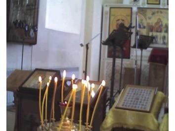
E3S Web of Conferences 263, 04013 (2021)                                    https://doi.org/10.1051/e3sconf/202126304013
FORM-2021

         on the table top of the candlestick. The obtained experimental data are shown in the form of
         a graph in Fig. 9 [16-17].

         Fig. 9. The graph of the change in air temperature t ° C along the height h, cm of the convective flow
         above a separately burning candle on a candlestick.

             From the analysis of the graph of the change in the air temperature t ° C along the vertical
         h, cm in the convective flow, we can conclude that the temperature changes slightly from 28
         to 28.9 ° C along the height of the candle from 0 to 20 cm and practically corresponds to the
         ambient temperature. A sharp increase in air temperature in the stream is observed above the
         burning candle up to 50.1 °C and gradually decreases at a height of 60 cm to 39.2 ° C and at
         an altitude of 100 cm the air temperature in the stream corresponds to the ambient temperature
         in the church building.
             At a height of up to 60 cm, the convective flow remains stable due to the presence of a
         high temperature. This allows you to maximally capture the harmfulness with the help of an
         exhaust umbrella installed above the candlestick at a height of 60 cm. The next stage of the
         experimental research was measuring the air temperature t ° C along the height h, cm along
         the axis of the cylindrical convective flow above the burning candles on the candlestick. The
         measurement results are shown in Fig 10.

         Fig.10. Graph of the change in air temperature t ° C along the height h, cm on the axis of the cylindrical
         convective flow above the burning candles on the candlestick.

                                                             6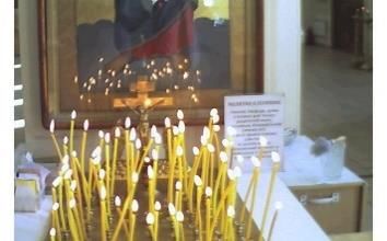
E3S Web of Conferences 263, 04013 (2021)                                  https://doi.org/10.1051/e3sconf/202126304013
FORM-2021

             It was found that the air temperature on the axis of the ascending convective flow is
         slightly lower than above the candles and varies from 25 ° C from the beginning of the flow
         to 25.2 °C vertically at a level of 20 cm. The air temperature at the level of 30 cm reaches
         33.1 °C. Then the temperature begins to decrease - at the level of 40 cm to 31.2 °C and to
         30.6 °C at a height of 60 cm and up to 30.0 °C at around 80 cm from the top of the candlestick
         tabletop. Further along the height, the temperature flows approach the state of the
         environment in the room. In the case under consideration, at a height of 0 to 70 cm, the
         convective flow is most stable, which is very important for the efficiency of the exhaust hood.
         Low air temperatures on the axis of the cylindrical convective flow are explained by the
         absence of burning candles inside the flow. In order to achieve high efficiency of the exhaust
         hood and determine the height of the installation above the candlesticks, studies of changes
         in the convective flow velocity V, m / s in the area of air temperature measurement were
         carried out (Fig. 10, 11). The obtained results of speed studies were carried out using a hot-
         wire anemometer and are shown in Fig. 11.

         Fig. 11. The graph of the change in air velocity V, m / s along the height h, cm of the convective flow
         above a separately burning candle on a candlestick.

             From the analysis of the data obtained, it follows that the air speed near the candle at a
         height of 0 to 20 cm varies slightly from 0.6 to 0.7 m/s, which corresponds to the mobility of
         air in the environment near the candlestick. A sharp increase in speed is observed in the jet
         above the candle flame at a height of 30cm and corresponds to 28m/s and reaches a maximum
         in the jet of 36m / s at around 40cm. Further, as you move away from the burning candle, the
         air velocity in the jet decreases to 23.8 m/s at a distance of 50 cm and 19.4 m/s at a height of
         60 cm and 6.6 m / s at 70 cm. The obtained results of the study of the temperature and air
         velocity (Fig. 10, 11, 12) allow us to determine the zone of stable convective flow within h
         50-60 cm. Therefore, the exhaust hood must be installed in the zone of stable convective
         flow, indicated in the range from the table top of the candlestick to the lower edge exhaust
         hood. These conditions will ensure effective trapping and removal of harmful substances
         when burning candles from the area of worship outside the premises. The proposed exhaust
         hoods are installed in the local mechanical exhaust ventilation system (Fig.12).
             In the specified ventilation system, it is recommended to install all candlesticks in one
         line along the outer wall of the worship hall at a distance convenient and safe for parishioners.
         Hazards released during the combustion of candles-3 and lamps-4 from umbrellas-5 enter the
         exhaust system of air duct-8 and then, using fan-6, are removed into the atmosphere through
         air duct-7.
             At 90cm, the air velocity in the jet corresponds to 0.2 m/s, as in the room. It is important
         to note that the air velocity at the edge of the jet above the flame is much lower and amounts

                                                           7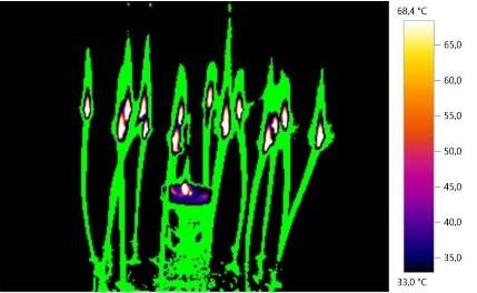
E3S Web of Conferences 263, 04013 (2021)                                       https://doi.org/10.1051/e3sconf/202126304013
FORM-2021

         to 1 m/s. On the basis of the studies carried out, the authors propose the following model of
         the structure of a convective air flow as a result of heat release from open burning of candles
         on a candlestick Fig. 12. In this case, the revealed values of temperature and air mobility in
         the convective flow, obtained using a thermal imager and a hot-wire anemometer, were used.
         When forming the model, the methods of Shepelev I.A.

         Fig.12. Scheme of the structure of the total convective jet above the flame of burning candles above the
         candlestick table top: a-cylindrical; b - rectangular. I - passive section of adjacent air leakage; II - active
         area of adjacent air leakage; III - acceleration section; IV - section of expansion of each candle due to
         the leakage of adjacent air; hI, hII, hIII, hiv — height of the corresponding zone, cm; VI, VII, VIII, Viv
         - air speed in the corresponding section, m / s; tI, tII, tIII, tiv - air temperature in the corresponding
         section, оС; tos, Vos - respectively, temperature and velocity on the axis of the total convective jet; tav,
         Vav - respectively, the average temperature and velocity on the axis of the total convective jet; L is the
         air flow rate in the total convective jet m3 /h; 1 - candlestick; 2 - table top; 3- convective flow from a
         separate candle; 4 - candle; 5 - icon lamp; 6 - the hollow part of the cylindrical convective flow.

             The obtained results of the study of the temperature and air velocity (Fig. 10, 11, 12)
         allow us to determine the zone of stable convective flow within h 50-60 cm. Therefore, the
         exhaust hood must be installed in the zone of stable convective flow, indicated in the range
         from the table top of the candlestick to the lower edge exhaust hood. These conditions will
         ensure effective trapping and removal of harmful substances when burning candles from the
         area of worship outside the premises. The proposed exhaust hoods are installed in the local
         mechanical exhaust ventilation system (Fig.13)

         Fig. 13. The proposed scheme of the local mechanical exhaust ventilation system: 1 - candlestick; 2-
         table top; 3 - candle; 4 - icon lamp; 5 - exhaust hood; 6 - fan; 7 - removal of polluted air; 8 - air duct
         system; h is the distance from the table top to the lower edge of the umbrella.

                                                               8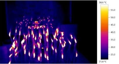
E3S Web of Conferences 263, 04013 (2021)                             https://doi.org/10.1051/e3sconf/202126304013
FORM-2021

              The proposed local exhaust ventilation system will provide comfortable conditions for
         parishioners and will preserve the interior decoration of the worship hall of the church, temple
         and cathedral. To effectively trap polluted heated air with an exhaust hood, it is important to
         know the regularities of the convective flow. In this case, the heat flow has four sections I,
         II, III and IV (Fig. 12), which differ from each other by changing the air flow rate L m 3 / h,
         temperature t ° C, velocity V m / s and the nature of the flow. In passive section I, there is a
         slight leakage of ambient air L m3 / h to the source of candle combustion at low V m / s and
         t ° C. Active section II is characterized by intensive inflow of adjacent air to the combustion
         site and acceleration of the adjacent air to the combustion site and acceleration of the
         convective flow mass movement, which leads to the formation of a narrow part of the flow
         cross section. The acceleration of the convective flow occurs in section III, then in section
         IV the convective flow begins to gradually expand due to the leakage of adjacent air and then
         dies out and dissolves in the environment. The revealed features and sections of the
         convective flow are necessary to determine the size and volume of the exhaust hood, the
         location of its installation, the distance from the place of burning candles to the lower edge
         of the hood. It has been established that the total convective flow consists of separate
         individual convective flows (Fig. 8.9) of air, formed from each separate burning candle,
         which in section IV do not interconnect, but when decaying are mixed with the environment.
         These judgments are justified by the value of t °C and V m / s, shown in the graph in Fig. 9,
         10, 11 and Fig. 12. It is proposed to install the hoods over the burning candles. The space
         between the candles and the lower edge of the umbrella covers areas I, II, and III at a distance
         of 50 to 60 cm and provides free flow of adjacent air. This contributes to the complete
         removal of combustion products from candles: heat, soot, steam, soot and carbon dioxide.
         The conducted research and the results obtained make it possible to develop a methodology
         for calculating the local exhaust ventilation system and the dimensions of the exhaust hood
         for trapping and removing the harmfulness generated by burning candles on candlesticks and
         ensuring the preservation of historical and artistic values in the hall of worship, as well as
         creating comfortable conditions for parishioners and staff Orthodox churches, cathedrals and
         temples.

         References
         1. Dmitrieva L.S., Kuzmina L.V., Moshkarnev L.M. Planning an experiment in ventilation
            and air conditioning. [Planiruyem eksperiment po ventilyatsii i konditsionirovaniyu].
            Irkutsk .: Irkutsk University, 1987.210p. (rus)
         2. Kassandrova ON, Lebedev VV. Processing of observation results. [Obrabotka rezul'tatov
            nablyudeniya]. Moscow: Nauka, 1970.210p. (rus)
         3. Uspenskaya G.V. Mathematical statistics in ventilation technology. [Matematicheskaya
            statistika v ventilyatsionnoy tekhnike]. M .: Stroyizdat, 1980.108 p. (rus)
         4. Shepelev I.A. Indoor air flow aerodynamics. [Aerodinamika vozdushnogo potoka v
            pomeshchenii]. M .: Stroyizdat, 1978.178p. (rus)
         5. Kochev A.G. Microclimate of Orthodox churches. [Mikroklimat pravoslavnykh
            khramov]. NNGASU. 2004.449p. (rus)
         6. Annunciation. How can temples breathe? [Kak khramy mogut dyshat']. [Electronic
            resource]. URL: https://blagovest.ru/blog/chem-dyshat-khramy. (date of treatment
            12/02/2020). (rus)
         7. Eremkin A.I., Ponomareva I.K., Bagdasaryan A.G. Analysis and methods of providing a
            microclimate in Orthodox cathedrals and temples. [Analiz i metody obespecheniya
            mikroklimata v pravoslavnykh soborakh i khramakh]. Education and Science in the
            Modern World. Innovation. 2020. No. 4. P. 151-158. (rus)

                                                        9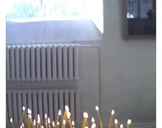
E3S Web of Conferences 263, 04013 (2021)                           https://doi.org/10.1051/e3sconf/202126304013
FORM-2021

         8. Eremkin A.I., Ponomareva I.K., Petrova K.A., Bagdasaryan A.G. Ways to improve the
             quality of the microclimate in the worship hall of the Spassky Cathedral in Penza.
             [Sposoby uluchsheniya kachestva mikroklimata v molel'nom zale Spasskogo sobora v
             Penze]. Regional architecture and construction. 2020. No. 4. P. 125-136. (rus)
         9. Eremkin A.I., Ponomareva I.K., Bagdasaryan A.G. The influence of the sanitary and
             hygienic state of the microclimate in the halls of worship of Orthodox cathedrals on the
             physiological state of parishioners. [Vliyaniye sanitarno-gigiyenicheskogo sostoyaniya
             mikroklimata v molel'nykh zalakh pravoslavnykh soborov na fiziologicheskoye
             sostoyaniye prikhozhan]. Education and Science in the Modern World. Innovation. 2020.
             No. 6. P. 151-155. (rus)
         10. Kochev A.G. Microclimate conditioning systems in Orthodox churches. [Sistemy
             konditsionirovaniya mikroklimata v pravoslavnykh khramakh]. M .: AVOK – Press.
             2009. 230 p. (rus)
         11. Konovalov, V.I. Technical thermodynamics [Tekhnicheskaya termodinamika]. Ivanovo:
             Ivanovo State Power Engineering University named after V.I. Lenin. 2005 .620 p
         12. Orlov M.E. Theoretical foundations of heat engineering. Heat and mass transfer
             [Teoreticheskiye osnovy teplotekhniki. Teplomassoobmen]. Ulyanovsk: UlGTU.
             2013.204 p.
         13. Bukhmirov      V.V.      Non-stationary    thermal     conductivity   [Nestatsionarnaya
             teploprovodnost]. Ivanovo: Ivanovo State Power Engineering University named after V.I.
             Lenin.2013.360 p.
         14. Miram A.O. Technical thermodynamics. Heat and mass transfer [Tekhnicheskaya
             termodinamika]. M.: ASV. 2011.352 p.
         15. Kudinov A.A. Heat and mass transfer [Teplomassoobmen]. M.: INFRA-M. 2012.374 p.
         16. Bearzi V. Luoghi di culto. Impianti Radianti o Misti. RCI. Febraio. 2003.
         17. Rahimian A.Yoram Eilon. New York's Hearst Tower. A Restoration, an Adaptive Reuse
             and a Modern Steel Tower Rolled Into One. Structure magazine 2006. No 02, - P. 25-29.

                                                     10
You can also read