Materials Advances COMMUNICATION

Page created by Robin Austin
 
CONTINUE READING
Materials Advances COMMUNICATION
Materials
                                                                                                               Advances
           This article is licensed under a Creative Commons Attribution-NonCommercial 3.0 Unported Licence.

                                                                                                                                                                                                                                       View Article Online
                                                                                                                   COMMUNICATION                                                                                                       View Journal | View Issue

                                                                                                                                                      [24]Crown-8-modified carbon nanotubes for
                                                                                                                                                      templating metal deposition and active materials
                                                                                                               Cite this: Mater. Adv., 2021,
Open Access Article. Published on 26 lokakuuta 2020. Downloaded on 12.2.2021 8.51.56.

                                                                                                               2, 236                                 for pseudocapacitors†
                                                                                                               Received 15th September 2020,
                                                                                                               Accepted 23rd October 2020             Ruitao Zhou,‡a Fung-Kit Tang,‡a Raymond Wai-Yin Sun,b Man Kin Tse,b
                                                                                                                                                      Yujie Chen,b Albert Sun Chi Chan,b Shengzhou Chen, c Xunjin Zhu *a and
                                                                                                               DOI: 10.1039/d0ma00701c
                                                                                                                                                      Ken Cham-Fai Leung *a
                                                                                                               rsc.li/materials-advances

                                                                                                               A uniform nickel film could be coated on crown ether-modified carbon           both substrates and current collectors.4 However, the thickness
                                                                                                               nanotubes (c-CNTs) by electroless deposition. The products CNT@Ni              of the metal oxide layer is on the nanoscale and the mass
                                                                                                               and c-CNT@Ni were oxidized and compressed into CNT@Ni@(NiOH)2                  loading of metal oxides on current collectors is low (usually less
                                                                                                               and c-CNT@Ni@(NiOH)2 discs, respectively. The areal and volumetric             than 1 mg cm 2). The areal and volumetric capacitances of
                                                                                                               capacitances of CNT@Ni@(NiOH)2 and c-CNT@Ni@(NiOH)2 were com-                  electrodes are more important parameters in the evaluation of
                                                                                                               pared and c-CNT@Ni@(NiOH)2 showed a lower resistance.                          electrochemical performance of the active materials than the
                                                                                                                                                                                              specific capacitances.
                                                                                                               A hybrid between the lithium ion battery1 and the supercapa-                      In order to synthesize low cost electrodes with both a high
                                                                                                               citor is known as a pseudocapacitor, which has a high theore-                  areal capacitance and volumetric capacitance, herein, nanopor-
                                                                                                               tical specific capacitance. Most of them are made of metal                     ous nickel with a Ni(OH)2 shell and nanoporous nickel–iron
                                                                                                               oxides but their reported capacitances are often much lower                    with an Fe2O3 shell were synthesized. Nanoporous metal net-
                                                                                                               than their theoretical values because of two reasons: (1) the low              works were fabricated by stacking metal nanotubes together
                                                                                                               conductivity of metal oxides and (2) the low ion diffusion rates                and fusing them at high temperature, while the metal nano-
                                                                                                               of electrolyte inside the metal oxides during the charge–dis-                  tubes were synthesized by coating Ni and Fe on CNTs and
                                                                                                               charge process. To improve the ion diffusion and electron                      crown ether-modified CNTs (c-CNTs) through an electroless
                                                                                                               transmission in the pseudocapacitor, one strategy is shortening                deposition (ELD) process. The resulting surface oxidized nano-
                                                                                                               the electron and ion transfer pathway by synthesizing metal                    porous metal network can function as a high performance
                                                                                                               oxides at the nanoscale, such as nanoparticles2 and                            freestanding electrode itself. As compared to the reported metal
                                                                                                               nanoplates.3 Nanoarchitectured metal oxides can be combined                    oxide based electrode materials, for example, CNT@Ni(OH)2,5
                                                                                                               mechanically with current collectors to form electrodes, but the               CNT@Ni@Ni2(CO3)(OH)26 nanotubes and Ni fiber@Ni(OH)2,7
                                                                                                               contact interface has a high resistance and the resulting                      this work presented nanoporous architectures with high con-
                                                                                                               specific capacitance is not satisfactory for application. Another              ductivities and large specific surface areas. Hence, high areal
                                                                                                               method to improve the contact between metal oxides and                         and volumetric capacitances can be achieved using our new
                                                                                                               current collectors is synthesizing the metal oxides on the                     CNT@Ni@Ni(OH)2, c-CNT@Ni@Ni(OH)2 and CNT@Ni–Fe@Fe2O3
                                                                                                               current collectors directly. Carbon fabrics and metal foams                    materials.
                                                                                                               with a large specific surface area have been widely used as                       There are several factors that determine the capacitances of
                                                                                                                                                                                              materials: mass loading, resistance (contact between the active
                                                                                                                                                                                              materials and current collectors), scalability and the nanopor-
                                                                                                               a
                                                                                                                 Department of Chemistry, The Hong Kong Baptist University, Kowloon Tong,
                                                                                                                                                                                              ous structures. A modified ELD method was employed to
                                                                                                                 Kowloon, Hong Kong SAR, P. R. China. E-mail: xjzhu@hkbu.edu.hk,
                                                                                                                 cfleung@hkbu.edu.hk
                                                                                                                                                                                              deposit nickel on the substrate of multi-walled carbon nano-
                                                                                                               b
                                                                                                                 Guangzhou Lee & Man Technology Company Limited, 8 Huanshi Avenue, Nansha,    tubes (MWCNTs).8 It is also worth noting that MWCNTs are
                                                                                                                 Guangzhou, P. R. China                                                       readily available commercially in large quantities with relatively
                                                                                                               c
                                                                                                                 School of Chemistry and Chemical Engineering, Guangzhou University,          inexpensive prices, therfore the cost of production can be
                                                                                                                 Guangzhou, P. R. China
                                                                                                                                                                                              further reduced for industrial application.9
                                                                                                               † Electronic supplementary information (ESI) available: Experimental, micro-
                                                                                                               scopic analysis, electrochemical analysis, NMR spectra. See DOI: 10.1039/
                                                                                                                                                                                                 The synthesis of the amine-functionalized crown ether
                                                                                                               d0ma00701c                                                                     (DB24C8-CH2NH2) was achieved through a new synthetic path-
                                                                                                               ‡ These authors contributed equally to this work.                              way (Fig. 1B). Starting with diol 1, ditosylation yielded ditosylate

                                                                                                               236 | Mater. Adv., 2021, 2, 236--240                                                © 2021 The Author(s). Published by the Royal Society of Chemistry
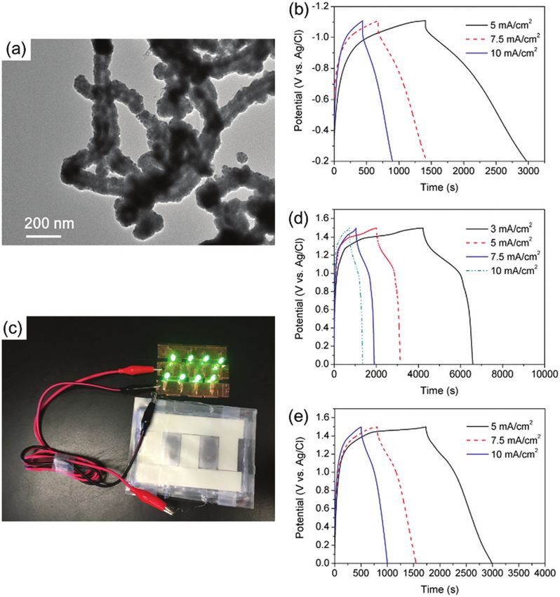
Materials Advances COMMUNICATION
View Article Online

                                                                                                               Communication                                                                                                                 Materials Advances
           This article is licensed under a Creative Commons Attribution-NonCommercial 3.0 Unported Licence.
Open Access Article. Published on 26 lokakuuta 2020. Downloaded on 12.2.2021 8.51.56.

                                                                                                               Fig. 1 (A) Synthetic scheme of dibenzo[24]crown-8-CH2NH2 (DB24C8-
                                                                                                               CH2NH2), conditions: (a) TsCl, NEt3, DMAP, r.t., CH2Cl2, 24 h, 67%; (b) 3,4-
                                                                                                               dihydroxybenzonitrile, Cs2CO3, K2CO3, MeCN, reflux, 24 h, 68%; (c) LiAlH4,
                                                                                                               THF, reflux, overnight, 41%. (B) Synthetic process of interconnected
                                                                                                               CNT@Ni and crown ether-based c-CNT@Ni via CNT@Ag and c-CNT@Ag
                                                                                                               by electroless deposition (ELD).

                                                                                                               2 in 67% yield. Then, ditosylate 2 was macrocyclized with 3,4-
                                                                                                               dihydroxybenzonitrile using a cesium ion template to yield
                                                                                                               macrocycle 3 in 68% yield. The cyano group of macrocycle 3
                                                                                                               was reduced into the product DB24C8-CH2NH2 by LiAlH4 in
                                                                                                               41% yield (Fig. S1–S6, ESI†). Then, the surface of the CNTs was
                                                                                                               oxidized in acidic medium, and both crown ether modified
                                                                                                               CNTs (c-CNTs) and pristine oxidized CNTs were used as sub-
                                                                                                               strates to initiate ELD of Ni using a silver nitrate catalyst
                                                                                                               (Fig. 1A and Fig. S7, ESI†). The carboxyl groups on CNTs were
                                                                                                               activated by SOCl2 and then subsequently reacted with the
                                                                                                               crown ether DB24C8-CH2NH2 to yield c-CNTs through amide
                                                                                                               bonds. The crown ether modification on the CNTs was further
                                                                                                               confirmed by XPS analysis (Fig. S8, ESI†).
                                                                                                                   During the ELD process, Ag+ acts as the catalytic site for Ni
                                                                                                               adhesion, and the use of a crown ether as an adsorbent for Ag+
                                                                                                               ions has been reported,10 hence c-CNTs could provide anchor-
                                                                                                               ing points for Ag+ and a more uniform metal coating could
                                                                                                               be formed. The adsorption of Ag+ on c-CNTs was confirmed
                                                                                                               by EDX characterization (Fig. S9, ESI†). For the pristine CNTs,
                                                                                                               the absorption of silver ions was characterized by XPS; two                    Fig. 2 TEM images of (a) nickel islands on CNTs; (b) connected Ni islands
                                                                                                               peaks with the binding energy of 368.4 eV and 374.6 eV were                    on CNTs; (c) continuous Ni film on CNTs; (d) interconnected CNT@Ni with
                                                                                                               observed, corresponding to Ag 3d5/2 and Ag 3d3/2 respectively                  side branches; (e–h) interconnected c-CNT@Ni with side branches.
                                                                                                               (Fig. S11a, ESI†). Also, Ag+ has a lower catalytic rate for ELD
                                                                                                               compared to that of palladium,11 which is advantageous for
                                                                                                               controlling the mass loading and morphology of nickel depos-                   interconnected CNT@Ni with side nickel branches (Fig. 2a–d).
                                                                                                               ited on the CNTs, such as by tuning the amount of reducing                     Notably, with crown ether modification, the nickel coating on
                                                                                                               agent dimethylamine borane (DMAB) and reaction time. The                       c-CNT@Ni is more evenly distributed and smoother than that
                                                                                                               homogeneous deposition of nickel in the bulk solution was                      of CNT@Ni (Fig. 2e–g), and interconnected branches were
                                                                                                               diminished with the use of Ag+ and c-CNTs.                                     arranged in a more uniform way (Fig. 2d and h). Without
                                                                                                                   The ELD process was carried out with the assistance of                     ultrasound, the branches could not be formed to connect the
                                                                                                               ultrasonication (45 kHz) for dispersion. Through the adjust-                   CNT@Ni and only a thicker metal deposit was observed (Fig.
                                                                                                               ment of the concentration of the reducing agent (DMAB) and                     S10, ESI†). This is possibly due to the interference of diffusion
                                                                                                               pH of the solution, nickel with different morphological struc-                  rates of Ni2+ for the growth of branches during the ELD process.
                                                                                                               tures was synthesized on the CNTs, such as separated nickel                    The nickel coating on CNT@Ni was characterized by XPS (Fig.
                                                                                                               islands, connected nickel islands, continuous nickel films and                 S11b, ESI†) and XRD (Fig. S11c, ESI†). The resulting CNT@Ni

                                                                                                               © 2021 The Author(s). Published by the Royal Society of Chemistry                                               Mater. Adv., 2021, 2, 236--240 | 237
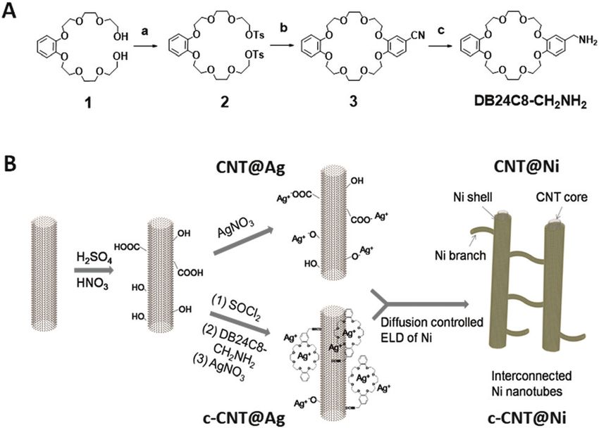
Materials Advances COMMUNICATION
View Article Online

                                                                                                               Materials Advances                                                                                                            Communication

                                                                                                               and c-CNT@Ni were tested as positive electrodes in aqueous                   The oxidation of CNT@Ni was also characterized by XRD
                                                                                                               NaOH electrolyte. Subsequently, the Ni surface was oxidized               (Fig. S11c, ESI†). In the VSM test (Fig. S11d and S13a, ESI†), the
                                                                                                               in situ to form the active Ni(OH)2 materials on the electrodes            magnetic moments of the electrodes decreased after electro-
                                                                                                               after the first charging–discharging process (Fig. S7, ESI†).             chemical testing because of a gradual oxidation on the Ni layer.
           This article is licensed under a Creative Commons Attribution-NonCommercial 3.0 Unported Licence.

                                                                                                                  For electrochemical studies, the CNT@Ni material was                   The oxidation of Ni was fast in the first charge–discharge cycle,
                                                                                                               then fabricated into the area of a 1 cm2 disc as a working                and 5.6% Ni was converted into Ni(OH)2. After optimization,
                                                                                                               electrode. A piece of nickel cloth was fabricated using a                 the CNT@Ni freestanding electrode was shaped in a round
                                                                                                               reported method12 and directly used as the current collector.             plate (inset of Fig. 3c) with a thickness of 0.253 mm whereas
                                                                                                               The CNT@Ni film had a high specific surface area of 61 m2 g 1             CNT@Ni has a high density of 2.97 g cm 3.
                                                                                                               based on the Brunauer–Emmett–Teller analysis, and such a                     Compared to the CNT@Ni film fabricated by filtration, the
                                                                                                               highly porous structure can facilitate the ion transfer between           optimized CNT@Ni plate had smaller pores with sizes of
Open Access Article. Published on 26 lokakuuta 2020. Downloaded on 12.2.2021 8.51.56.

                                                                                                               the electrolyte and the electrode (Fig. S12a and b, ESI†). The            around several hundred nanometers (Fig. 3a and b). In the
                                                                                                               internal resistance of the porous CNT@Ni film is about 2.4 O,             GCD test, the areal capacitances of the CNT@Ni electrode were
                                                                                                               which is estimated from the x-intercept of the electrochemical            27.7, 28.9, 30.1, 31.5 and 31.2 F cm 2 at the current density of 5,
                                                                                                               impedance spectroscopy (EIS) curve (Fig. S11d, ESI†). By galva-           7.5, 10, 15 and 20 mA cm 2, respectively (Fig. 3d). The increase
                                                                                                               nostatic charge–discharge (GCD) testing, the areal capacitances           in both capacitance and current densities could result from an
                                                                                                               of the electrode were found to be 34.2, 34.0, 33.9, 32.6                  increased IR drop and the non-linear charging of the electro-
                                                                                                               and 22.5 F cm 2 at the current density of 5, 7.5, 10, 15 and              des. With regards to the thickness and weight of the electrode,
                                                                                                               20 mA cm 2, respectively (Fig. S12f, ESI†). The presence of               the capacitances of the electrode based on volume and weight
                                                                                                               plateaus in the discharging curves of GCD and redox peak pairs            at 20 mA cm 2 are 1232 F cm 3 and 414.5 F g 1, respectively.
                                                                                                               in cyclic voltammetry (CV) curves suggest that the capacitance            Compared to the CNT@Ni film fabricated by filtration, the
                                                                                                               of the porous CNT@Ni film follows a faradaic mechanism                    resistance of the electrode decreased from 3.4 O to 2.2 O
                                                                                                               (Fig. S12e and f, ESI†). The faradaic capacitance of the                  according to EIS characterization (Fig. 3e). The Ni(OH)2 layer
                                                                                                               electrode originated from the nickel hydroxide layer formed               was fully accessible to OH , and the specific capacitance of
                                                                                                               on the surface of CNT@Ni during the charge–discharge                      Ni(OH)2 was 1765 F g 1 at the current density of 40 mA cm 2.
                                                                                                               process, because Ni can be oxidized into Ni(OH)2 in alkaline              However, the CNT@Ni film is stacked loosely by compression,
                                                                                                               solution.13                                                               and the contact part between CNT@Ni could be oxidized and
                                                                                                                                                                                         result in an increased internal resistance (Fig. S12d, ESI†).

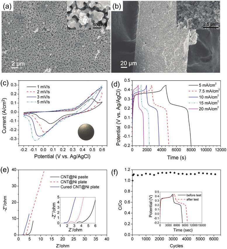
                                                                                                               Fig. 3 (a and b) SEM images of the CNT@Ni plate (a, front surface; b,
                                                                                                               section), (c) CV curves of the CNT@Ni plate (inset: photo of a CNT@Ni     Fig. 4 (a) TEM image of CNT@Ni–Fe, (b) GCD curves of CNT@Ni–Fe@Fe2O3
                                                                                                               plate), (d) GCD curves of the c-CNT@Ni plate, (e) electrochemical impe-   freestanding electrodes, (c) eight LEDs powered by two serially connected
                                                                                                               dance spectra of CNT@Ni; (f) long cycle test of CNT@Ni by cyclic          flexible supercapacitors, (d) GCD curves of a supercapacitor assembled by
                                                                                                               voltammetry at 50 mV s 1 (inset: GCD curves at 5 mA cm 2 before and       CNT@Ni(OH)2 and CNT@Ni–Fe@Fe2O3, and (e) GCD curves of a supercapa-
                                                                                                               after the long cycle test).                                               citor assembled by c-CNT@Ni(OH)2 and CNT@Ni–Fe@Fe2O3.

                                                                                                               238 | Mater. Adv., 2021, 2, 236--240                                           © 2021 The Author(s). Published by the Royal Society of Chemistry
View Article Online

                                                                                                               Communication                                                                                                        Materials Advances

                                                                                                               Table 1    Summary of performance of different as-prepared materials

                                                                                                                                                                Electrode            Areal             Volumetric                                  Internal
                                                                                                               Samples                                          type                 capacitancea      capacitancea       Energy density           resistance
                                                                                                                                                                                     31.2 F cm 2       1232 F cm 3
           This article is licensed under a Creative Commons Attribution-NonCommercial 3.0 Unported Licence.

                                                                                                               CNT@Ni@Ni(OH)2                                   Positive                                                  N/A                      2.2 O
                                                                                                               CNT-GO@Ni@Ni(OH)2                                Positive             63.65 F cm 2      1140 F cm 3        N/A                      N/A
                                                                                                               c-CNT@Ni@Ni(OH)2                                 Positive             23.3 F cm 2       960 F cm 3         N/A                      1.6 O
                                                                                                               CNT@Ni–Fe@Fe2O3                                  Negative             11.8 F cm 2       524 F cm 3         N/A                      N/A
                                                                                                               Assembled with CNT@Ni@Ni(OH)2 and                Asymmetric           4.8 F cm 2        172 F cm 3         12 W h kg 1              N/A
                                                                                                               CNT@Ni–Fe@Fe2O3                                                                                            (35 mW h cm 3)
                                                                                                                                                                                                 2
                                                                                                               Assembled with c-CNT@Ni@Ni(OH)2 and              Asymmetric           4.24 F cm         N/A                8.2 W h kg 1             N/A
                                                                                                               CNT@Ni–Fe@Fe2O3                                                                                            (23.7 W h cm 3)
                                                                                                               a
                                                                                                                   Measured at the current density of 20 mA cm 2.
Open Access Article. Published on 26 lokakuuta 2020. Downloaded on 12.2.2021 8.51.56.

                                                                                                                  For long testing cycles, the continuous oxidation of the Ni            Through the sequential deposition of Ni and Fe on CNTs,
                                                                                                               layer caused damage to the contact surface, leading to internal           CNT@Ni–Fe was synthesized, and CNT@Ni–Fe@Fe2O3 was
                                                                                                               resistance (Fig. S14, ESI†). For further optimization, the elec-          obtained by the oxidation of CNT@Ni–Fe in hydrogen peroxide.
                                                                                                               trode was cured at 350 1C in nitrogen for 20 min to fuse the              The sequential deposition of Ni and Fe on CNTs was character-
                                                                                                               contact between CNT@Ni to give a connected 3-D metal net-                 ized by EDX (Fig. S18, ESI†) while the oxidation of the Fe2O3
                                                                                                               work. The inner resistance of the electrode further decreased to          layer on CNT@Ni–Fe was confirmed by XRD (Fig. S19, ESI†).
                                                                                                               1.5 O (Fig. 3e), indicating that the contact between CNT@Ni               The TEM image of CNT@Ni–Fe showed that Ni and Fe were
                                                                                                               was improved by the curing process. The cured electrode was               uniformly coated on the CNTs (Fig. 4a). CNT@Ni–Fe@Fe2O3
                                                                                                               tested up to 6000 cycles using a continuous cyclic voltammetry            freestanding electrodes (thickness 0.277 mm) showed high
                                                                                                               test at 50 mV s 1 (Fig. 3f). The capacitance of the electrode can         areal and volumetric capacitances via the GCD test (Fig. 4b)
                                                                                                               be maintained at 117% of the original capacitance after testing           of 11.8 F cm 2 and 524 F cm 3, respectively.
                                                                                                               for 6000 cycles. An additional GCD test was performed                        An asymmetric supercapacitor was fabricated using
                                                                                                               before and after the long cycle test (inset of Fig. 3f), and the          CNT@Ni@Ni(OH)2 as the positive electrode and CNT@Ni–
                                                                                                               capacitance of the electrode by GCD at 5 mA cm 2 was                      Fe@Fe2O3 as the negative electrode (Fig. S20, ESI†) with a
                                                                                                               increased by 27%, and this phenomenon was consistent with                 balanced mass ratio of 2 : 5, according to the principle of
                                                                                                               that of the reported Ni@NiO core–shell electrodes fabricated              conservation of charge (Q+ = Q ). From the GCD curves in
                                                                                                               with activated nickel foam.14                                             Fig. 4d, the areal and volumetric capacitances of the device
                                                                                                                  We next fabricated a freestanding electrode with c-CNT@Ni,             based on the two electrodes were 4.8 F cm 2 and 172 F cm 3,
                                                                                                               and similar optimization strategies and electrochemical mea-              respectively. Calculated by the integration of GCD discharge
                                                                                                               surements were carried out via GCD, CV and EIS spectroscopies             curves (Fig. 4d), the device had an energy density of 12 W h kg 1
                                                                                                               (Fig. 3d and Fig. S15, ESI†). The areal capacitances of the               (35 mW h cm 3) based on the overall electrodes. For compar-
                                                                                                               c-CNT@Ni electrode plate were 22.0, 22.3, 22.5, 22.9 and                  ison, another asymmetric supercapacitor was assembled using
                                                                                                               23.3 mF cm 2 at the current density of 5, 7.5, 10, 15 and                 c-CNT@Ni@Ni(OH)2 as the positive electrode. From the GCD
                                                                                                               20 mA cm 2, respectively. With regard to the plate electrode              discharge curves (Fig. 4e), the supercapacitor had a capacitance
                                                                                                               with the thickness of 0.243 mm, c-CNT@Ni has a volumetric                 of 4.24 F cm 2 at the current density of 5 mA cm 2, which
                                                                                                               capacitance of 960 F cm 3 at the current density of 20 mA cm 2.           corresponded to an energy density of 8.2 W h kg 1 (23.7 W h cm 3).
                                                                                                               The measured areal and volumetric capacitances of c-CNT@Ni                As a demonstration, a light-emitting diode (LED) array was powered
                                                                                                               are similar to those of CNT@Ni, but the inner resistance and              by two series of flexible connected supercapacitors (Fig. 4c).
                                                                                                               charge transfer resistance of c-CNT@Ni are 1.6 O, and 0.6 O,
                                                                                                               respectively, via EIS (Fig. S15c, ESI†), hence giving a better
                                                                                                               energy output efficiency. A similar synthetic strategy can also be          Conclusions
                                                                                                               applied to nanocarbon materials with different morphologies
                                                                                                               such as graphene oxide (GO) to give nickel-coated graphene                The crown ether DB24C8-CH2NH2 was grafted onto CNTs to
                                                                                                               oxide (GO@Ni) and nickel-coated GO–CNT hybrid materials                   improve the absorption of Ag+ for uniform Ni deposition on
                                                                                                               (CNT–GO@Ni) (Fig. S16 and S17, ESI†). In comparison to the                CNTs. The ELD protocol was modified to control the metal
                                                                                                               reported electrodes with high areal capacitance, including                deposition morphology of interconnected CNT@Ni and
                                                                                                               HAB-MOF negative electrodes (23 F cm 2 & 760 F cm 3),15                   c-CNT@Ni. The electrodes based on the crown ether-modified
                                                                                                               MnO2/rGO@Ni(OH)2 positive electrodes (17.8 F cm 2),16 and                 CNTs (c-CNT@Ni@(NiOH)2) had lower inner resistance and
                                                                                                               CNT@PPy@MnO2 positive electrodes (16.1 F cm 2),17 both the                charge transfer resistance. Asymmetric supercapacitors were
                                                                                                               areal and volumetric capacitances of the electrodes have been             assembled using c-CNT@Ni@Ni(OH)2 and CNT@Ni–Fe@Fe2O3
                                                                                                               greatly improved to higher values in this work.                           as positive and negative electrodes. The nanoporous metal
                                                                                                                  To match the positive electrodes of CNT@Ni@Ni(OH)2                     networks with oxide/hydroxide shells reported in this work
                                                                                                               with a remarkable high areal capacitance, CNT@Ni–Fe@Fe2O3                 showed promising properties in achieving metal deposition
                                                                                                               nanoporous networks were synthesized as negative electrodes.              and electrochemical performances (Table 1).

                                                                                                               © 2021 The Author(s). Published by the Royal Society of Chemistry                                       Mater. Adv., 2021, 2, 236--240 | 239
View Article Online

                                                                                                               Materials Advances                                                                                                     Communication

                                                                                                               Conflicts of interest                                                 7 S. Xu, X. Li, Z. Yang, T. Wang, W. Jiang, C. Yang, S. Wang,
                                                                                                                                                                                       N. Hu, H. Wei and Y. Zhang, ACS Appl. Mater. Interfaces,
                                                                                                               There are no conflicts to declare.                                      2016, 8, 27868–27876.
                                                                                                                                                                                     8 R. Zhou, Y. Fu, K.-A. Chao and C.-H. Cheng, Renewable
           This article is licensed under a Creative Commons Attribution-NonCommercial 3.0 Unported Licence.

                                                                                                               Acknowledgements                                                        Energy, 2019, 135, 1445–1451.
                                                                                                                                                                                     9 R. Quintero, D. Y. Kim, K. Hasegawa, Y. Yamada, A. Yamada
                                                                                                               We acknowledge the financial support from the Guangdong                 and S. Noda, RSC Adv., 2014, 4, 8230–8237.
                                                                                                               Province Zhu Jiang Talents Plan (2016ZT06C090), the Guangz-          10 M. Hong, X. Wang, W. You, Z. Zhuang and Y. Yu, Chem.
                                                                                                               hou City Talents Plan (CYLJTD-201609), and the Nansha District          Eng., 2017, 313, 1278–1287.
                                                                                                               Research Project (2016GJ011). This work was partially supported      11 Y. Yu, C. Yan and Z. Zheng, Adv. Mater., 2014, 26,
                                                                                                               by The Hong Kong Baptist University.                                    5508–5516.
Open Access Article. Published on 26 lokakuuta 2020. Downloaded on 12.2.2021 8.51.56.

                                                                                                                                                                                    12 R. Guo, Y. Yu, Z. Xie, X. Liu, X. Zhou, Y. Gao, Z. Liu, F. Zhou,
                                                                                                               Notes and references                                                    Y. Yang and Z. Zheng, Adv. Mater., 2013, 25, 3343–3350.
                                                                                                                1 P. Simon, Y. Gogotsi and B. Dunn, Science, 2014, 343,             13 A. Seghiouer, J. Chevalet, A. Barhoun and F. Lantelme,
                                                                                                                  1210–1211.                                                           J. Electroanal. Chem., 1998, 442, 113–123.
                                                                                                                2 Y. Zou, C. Cai, C. Xiang, P. Huang, H. Chu, Z. She, F. Xu,        14 M. Yu, W. Wang, C. Li, T. Zhai, X. Lu and Y. Tong, NPG Asia
                                                                                                                  L. Sun and H.-B. Kraatz, Electrochim. Acta, 2018, 261, 537–547.      Mater., 2014, 6, e129–e129.
                                                                                                                3 X. Zhang, W. Shi, J. Zhu, W. Zhao, J. Ma, S. Mhaisalkar,          15 D. Feng, T. Lei, M. R. Lukatskaya, J. Park, Z. Huang, M. Lee,
                                                                                                                  T. L. Maria, Y. Yang, H. Zhang, H. H. Hng and Q. Yan, Nano           L. Shaw, S. Chen, A. A. Yakovenko, A. Kulkarni, J. Xiao,
                                                                                                                  Res., 2010, 3, 643–652.                                              K. Fredrickson, J. B. Tok, X. Zou, Y. Cui and Z. Bao, Nat.
                                                                                                                4 G. W. Yang, C. L. Xu and H. L. Li, Chem. Commun., 2008,              Energy, 2018, 3, 30–36.
                                                                                                                  6537–6539.                                                        16 S. Min, C. Zhao, Z. Zhang, K. Wang, G. Chen, X. Qian and
                                                                                                                5 S.-M. Bak, K.-H. Kim, C.-W. Lee and K.-B. Kim, J. Mater.             Z. Guo, RSC Adv., 2015, 5, 62571–62576.
                                                                                                                  Chem., 2011, 21, 1984–1990.                                       17 P. Li, Y. Yang, E. Shi, Q. Shen, Y. Shang, S. Wu, J. Wei,
                                                                                                                6 S. Chen, Q. Wu, M. Wen, C. Wang, Q. Wu, J. Wen, M. Zhu               K. Wang, H. Zhu, Q. Yuan, A. Cao and D. Wu, ACS Appl.
                                                                                                                  and Y. Wang, J. Phys. Chem. C, 2017, 121, 9719–9728.                 Mater. Interfaces, 2014, 6, 5228–5234.

                                                                                                               240 | Mater. Adv., 2021, 2, 236--240                                      © 2021 The Author(s). Published by the Royal Society of Chemistry
You can also read