Dynamic Wireless Power Transfer System for Electric Vehicles to Simplify Ground Facilities, Real-time Power Control and Efficiency Maximization ...
←
→
Page content transcription
If your browser does not render page correctly, please read the page content below
Special Issue - 2019 International Journal of Engineering Research & Technology (IJERT)
ISSN: 2278-0181
RTESIT - 2019 Conference Proceedings
Dynamic Wireless Power Transfer System for
Electric Vehicles to Simplify Ground Facilities,
Real-time Power Control and Efficiency
Maximization
Mr. Akshay M Mrs.Veenarani A V
Dept. of Electrical and Electronics Engg. Dept. of Electrical and Electronics Engg
Srinivas Institute of Technology, Mangaluru Srinivas Institute of Technology, Mangaluru
Abstract:- Wireless Power Transfer (WPT) is the process applied to the DWPT system. For maximizing the
where electrical energy is transferred from a power source to transmitting efficiency in the DWPT system, the mutual
an electrical load across an air gap using induction coils. inductance between a transmitter and a receiver has to be
These coils produce an electromagnetic field which sends estimated from the vehicle side. In this paper, an estimation
energy from a charging base station (transmitter) to a coil on
a portable device (receiver) with complete galvanic isolation.
method considering the vehicle-side control is proposed
The receiver coil takes power from electromagnetic field and and applied to the simultaneous power and efficiency
converts it into electrical power. control. The effectiveness of the proposed method is
This focuses on dynamic wireless power transfer for electric verified by simulations and experiments.
vehicles and proposes a vehicle-side control method for real-
time power control and efficiency maximization. The 2. WIRELESS POWER TRANSFER VIA MAGNETIC
proposed control strategy and controller design are presented RESONANCE COUPLING
based on a real-time estimation of the mutual inductance 2.1 Circuit analysis:
between a transmitter and a receiver. Simulations and The transmitter and the receiver coils are shown in Fig. 2.1.
experiments demonstrate that the proposed method can
achieve the maximum efficiency and the desired power
They are compensated by resonance capacitors for WPT
simultaneously. via magnetic resonance coupling, which can achieve a
highly efficient mid-range transmission and robustness to
1. INTRODUCTION misalignment. In this paper, a series-series (SS)
compensated circuit topology is used and its circuit
The transfer of energy from a source to a receiver has diagram is shown in Fig. 2.2. The transmitter and the
traditionally necessitated the use of a physical connection. receiver are characterized by the inductances L1, L2, the
Indeed, electrical grids and the power outlets span nearly series-resonance capacitances C1, C2, and the internal
the entire globe and deliver power to billions of people resistances R1, R2, respectively.Lm is the mutual inductance
worldwide. Recently, there has been much interest into the between the transmitter and the receiver.
area of wireless power transfer (WPT) that is the These parameters are expressed in Table 2.1. If power
transmission of power without the need for physical source angular frequency is designed as follows:
connection. Research into WPT, however is nothing new as
experiments in the field took place as far back as Nikola
Tesla in the early 20th century.
Wireless power transfer (WPT) is one of the hottest
research topics in transportation applications. In particular,
a dynamic wireless power transfer (DWPT) system for
electric vehicles (EVs) has gathered attention to extend the
cruising distance of EVs and to reduce the size of the
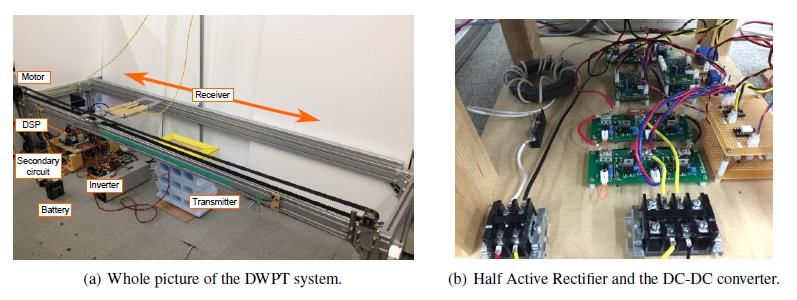
energy storage system. Its ground facilities are mainly
composed of power source, high-frequency inverters,
transmitters, and so on. As they are applied to rugged
roadways over long distances, power control and efficiency
maximization of wireless charging are desirable to be
F ig 2.1: Coil
achieved on the vehicle side without signal communication.
Although previous research has proposed simultaneous
control methods of power control and efficiency
maximization on the vehicle side, they have not been
Volume 7, Issue 08 Published by, www.ijert.org 1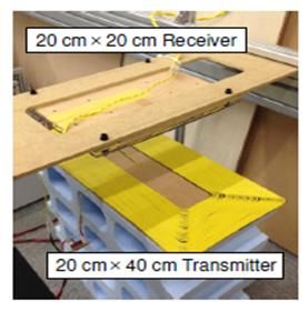
Special Issue - 2019                                                       International Journal of Engineering Research & Technology (IJERT)
                                                                                                                              ISSN: 2278-0181
                                                                                                         RTESIT - 2019 Conference Proceedings

                Table 2.1 : Parameters of the coil                                                   (ѡ0 Lm)2
                                                                                  R Lηmax = √R2{                + R2}       --- (2.4)
                               Transmitter            Receiver                                          R1
       Resistance R1, R2       1.95Ω                  1.6Ω                        Then, the transmitting power P is determined byR ηmax . As
       Inductance L1, L2       417.1µH                210µH                       a result, the desired power cannot be achieved only using
       Capacitance C1,         6030pF                 12110pF
       C2                                                                         RL optimization when the transmitting efficiency η is
       Resonant                100.4kHz               99.7kHz                     maximized.
       frequency f1, f2
       Coil gap                100mm                                              2.2 System configuration:
       Mutual                  36.3µH (no misalignment)                           In order to achieve the maximum efficiency and the desired
       Inductance Lm
       Coupling                0.122 (no misalignment)                            power simultaneously, the vehicle is equipped with two
       coefficient k                                                              power converters, i.e. Half Active Rectifier (HAR) and the
                                                                                  DC-DC converter. The circuit diagram of the DWPT
                                                                                  system is shown in Fig. 2.4. The ground facility consists of
                                                                                  voltage source VS and an inverter, which generates a square
                                                                                  wave voltage with resonance angular frequencyѡ0 . The
                                                                                  transmitting power P is rectified by the HAR and the
                                                                                  charging power PL is controlled by the DC-DC converter.
                                                                                  These control strategies and controller design methods are
                                                                                  described below.

         Fig. 2.3: Equivalent circuit of WPT system

                                                                                               Fig 2.5: Circuit diagram of the DWPT system.

                                                                                  3. Efficiency Maximization by Half Active Rectifier
                                                                                  3.1 DC link voltage control:
                                                                                  The HAR regulates the DC link voltageVdc for efficiency
                                                                                  maximization.Vdc Control is achieved using two operation
                                                                                  modes of HAR, which are shown in Fig. 3.1. When the
                                                                                  lower arm MOSFETs are off-state, HAR is operated as the
                                                                                  rectification mode. If the MOSFETs are turned on, HAR
                          Fig. 2.4: RL v/sη and P                                 becomes the short mode and the receiver is shorted.
                                                                                  Assuming the transmitting power P is larger than the load
         1            1                                                           power PL,Vdc is increased during the rectification mode. On
ѡ0 =            =                 --- (2.1)
       √L1 C1       √L2 C2                                                        the other hand,Vdc is decreased during the short mode
                                                                                  because P is cut-off and PL is supplied by the DC link
The transmitting efficiency η and the transmitting power P                        capacitor. Therefore, the waveform ofVdc can be depicted in
can be obtained as follows:                                                       Fig.3.2.
                (ѡ0 Lm)2 RL
η=                                            --- (2.2)
     R2 + RL{R1R2 + R1RL + (ѡ0 Lm)2 }

        (ѡ0 Lm)2 RL
P=                          V2                --- (2.3)
  {R1R2 + R1RL + (ѡ0 Lm)2 }2 1
Where V1 is the RMS value of the primary voltage and RL
is the load resistance. When VI equals to 100V, η and P are
expressed in Fig 2.3. In order to maximize the transmitting
efficiency η, RL has to be given as follows:

Volume 7, Issue 08                                               Published by, www.ijert.org                                                  2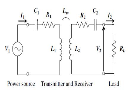
Special Issue - 2019                                                   International Journal of Engineering Research & Technology (IJERT)
                                                                                                                          ISSN: 2278-0181
                                                                                                     RTESIT - 2019 Conference Proceedings

                                                                              eq. (3.4), output y[i] and regressorφ[i] are determined as
                                                                              follows:
                                                                              y[i] = V1 + √V1 2 − 4R1 I2 [i](V2 [i] + R 2 I2 [i])--- (3.5)
                                                                              φ[i] = 2I2 [i]ѡ0                              --- (3.6)
                                                                              RLS filter is used to estimate Lm statistically by updating
                                                                              Lm[i], y[i] and φ[i] with following equations.
                                                                                                                φ[i]P[i−1]
                                                                                       Lm[i] = Lm[i − 1] +           2     ϵ[i]
                                                                                                                    λ+ φ[i] P[i−1]

                                                                              ϵ[i] = y[i] − φ[i]Lm[i − 1]

                                                                                     1                  φ[i]2 P[i−1]2
                                                                              P[i] = {P[i − 1] −                        }            --- (3.7)
                                                                                     λ                 λ+φ[i]2 P[i−1]
       Fig 3.1: Operation modes of Half Active Rectifier.                     Where λ is forgetting factor. The initial values are given as
              Fig 3.2: Waveform of the DC link voltage                        Lm[0] = 0 and P[0] = 1.In order to use the effective values
                                                                              for the estimation, the RLS filter updates Lm[i], y[i] and
If the upper boundVhigh and the lower boundVlow are                           φ[i] only during the rectification mode of the HAR. If the
defined as follows:                                                           HAR is operated as the short mode,Idc equals to 0 andthe
Vhigh = Vdc ∗ + ΔV        --- (3.1)                                           estimated value becomes incorrect. Therefore, the RLS
Vlow = Vdc ∗ − ΔV         --- (3.2)                                           filter has to be improved according to theoperation mode of
WhereVdc ∗ the reference value of the DC link voltage and                     the HAR.
ΔV is the hysteresis band,Vdc is kept within the desired
range.                                                                         4. POWER CONTROL BY THE DC-DC CONVERTER

3.2 Efficiency Maximization:                                                  4.1 Modeling of the DC-DC converter:
In order to maximize the transmitting efficiency, the load                    The DC-DC converter controls the load current i Lfor
resistance RL, which is expressed in Fig. 2.2 has to satisfy                  battery charging. Assuming the DC link voltage Vdcis
eq. (2.4) during the rectification mode. IfVdc ∗ is given as                  controlled to Vdcηmax by the HAR, the circuit diagram of the
follows:                                                                      DC-DC converter can be expressed in Fig. 4.1 (a). E is the
               R2            ѡ0 Lm                                            battery voltage, L is the inductance of the reactor coil and r
Vdcηmax = √                                  VS       --- (3.3)               is the internal resistance of the reactor coil and the battery.
               R1 √
                      R1R2+(ѡ0 Lm)2 +√R1R2
                                                                              In this paper, the DC-DC converter model is obtained by
                                                                              the state space averaging method. Assuming the DC-DC
RL is equated toR Lηmax and the transmitting efficiency η can                 converter is operated in the continuous conduction mode,
be maximized. On the other hand, during the short mode,                       its circuit diagram in each switching modes is expressed in
the transmitting power P is drastically decreased because                     Fig. 4.1 (b) and (c).
RL is minimized. As a result, losses during the short mode
are assumed to be negligible to losses during the
rectification mode in this paper. Therefore,Vdc ∗ is
determined only byVdcηmax .

3.3 Mutual inductance estimation:
For tracking the maximum efficiency in the DWPT system,
the mutual inductance Lm has to be estimated to
obtainVdcηmax .only using the vehicle-side information.
From the circuit equations of the DWPT system, the
estimation equation of Lm can be given as follows.
       V1 +√V1 2 −4R1 I2 (V2 +R2 I2 )                                                    Figure 4.1: Circuit diagram of the DC-DC converter.
Lm =                                      --- (3.4)
                    2I2 ѡ0
Although eq. (3.4) has two solutions, the solution with a                     From the circuit equation, the state equation of Fig.4.1 (b)
positive sign is used in this paper. Assuming the RMS                         is given as follows:
primary voltage V1 is constant and given to simplify                          d             r        1     1
                                                                                 i (t) = − iL (t) + E + Vdcηmax ---(4.1)
ground facilities, Lm can be estimated from the vehicle                       dt L          L        L     L
                                                                              Also, the state equation of Fig.4.1 (c) is described as
side. The RMS secondary voltage V2and the RMS
                                                                              follows:
secondary current I2are calculated from the DC link                           d             r        1
voltageVdc and the rectified DC currentIdc using Fourier                         i (t) = − iL (t) + E             --- (4.2)
                                                                              dt L          L        L
series expansions.                                                            When d(t) is defined as the duty cycle of the upper arm
In order to reduce the estimation error due to the sensor                     MOSFET S1, the state space model of the DC-DC
noise, recursive least square (RLS) filter is applied. From                   converter is obtained as follows:

Volume 7, Issue 08                                           Published by, www.ijert.org                                                         3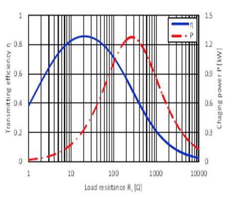
Special Issue - 2019 International Journal of Engineering Research & Technology (IJERT)
ISSN: 2278-0181
RTESIT - 2019 Conference Proceedings
d r 1 Vdcηmax The feedback controller is designed by the pole placement
i (t) = − iL (t) + E + dt --- (4.3)
dt L L L L method. As ΔPi(s)is the first-order system, we apply a PI
controllerCPI (s), which is expressed as follows:
In order to apply the linear control theory to the controller sK +K
design, this model is linearized around an equilibrium CPI (s) = P I --- (4.10)
s
point. When IL and D are defined as the equilibrium If closed loop poles are given by a multiple rootωd , the
point,iL (t) and d(t) are expressed as follows: gains are obtained as follows:
iL (t) = IL +ΔiL (t) ` --- (4.4)
2Lѡd −r
d(t) = D+Δd(t) --- (4.5) KP = --- (4.11)
Vdcηmax
whereΔiL (t)and Δd(t) are the microscopic fluctuations 2
Lѡd
around the equilibrium point. KI = --- (4.12)
Vdcηmax
By substituting eq. (4.4) and eq. (4.5) in eq. (4.3), the
Here,Vdcηmax and the gains are calculated by assuming the
linearized DC-DC converter model is given as follows:
d r Vdcηmax nominal value of Lmis 30Μh
i (t) = − ΔiL (t) + Δdt --- (4.6)
dt L L L
Therefore, the transfer function from Δd(s) to ΔiL (s) is 5. SIMULATION AND EXPERIMENT
obtained as follows: 5.1 Experimental setup:
ΔiL (s) Vdcηmax
ΔPi(s) = = --- (4.7) The experimental setup is shown in Fig. 5.1. The system
Δd(s) Ls + r
configuration is the same as Table 5.1. The receiver is
driven by the motor to simulate motion of the vehicle. The
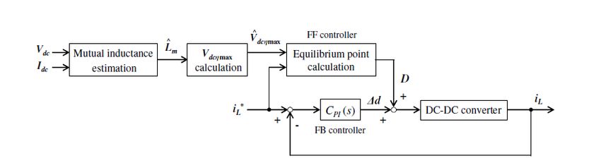
4.2 Controller design: inverter is operated only while the receiver is above the
Fig.4.2 shows the block diagram of the proposed control. transmitter to prevent huge power losses. Simulation and
The feed-forward controller is the same as the equilibrium experimental conditions are expressed in Table 5.1. The
point calculation, which is given by the constraint of the forgetting factor λ of the RLS filter was set to 0.95 and the
DC-DC converter. FromVdcηmax ,which is calculated from estimated mutual inductance Lm was updated only during
Lm, and the reference value of the load currentiL ∗ , the the rectification mode of the HAR. The reference value of
equilibrium point isobtained as follows: the DC link voltageVdcηmax was calculated from Lm and the
IL = iL ∗ --- (4.8) reference value of the load currentiL ∗ was set to 1.0 A.
E+rIL
D= --- (4.9)
Vdcηmax
Fig. 4.2: Block diagram of the proposed control.
Volume 7, Issue 08 Published by, www.ijert.org 4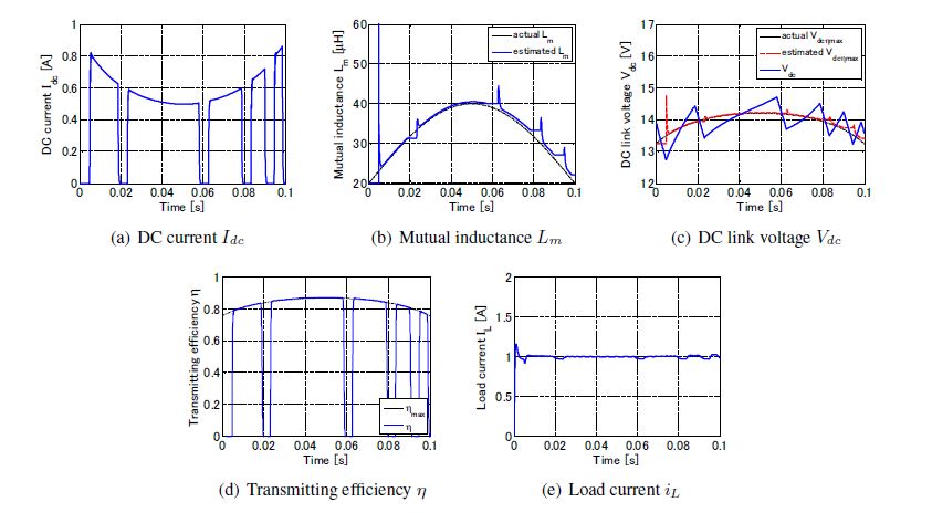
Special Issue - 2019                                                          International Journal of Engineering Research & Technology (IJERT)
                                                                                                                                 ISSN: 2278-0181
                                                                                                            RTESIT - 2019 Conference Proceedings

                                                                   Fig. 5.1: Experimental setup.

    Parameter          Value       Parameter          Value
    Power Source       18V         Battery voltage    6V
    Voltage VS                     E
    Operating          100kHz      Reactor            0.3Ω
    Frequency f0                   resistance r
    Hysteresis         0.5V        Reactor            1000µH
    band ΔV                        Inductance L
    Carrier            20kHz       DC         Link    200pF
    frequency fc                   capacitance Cdc

                                                                                                   Fig. 5.3: Simulation results with the proposed control.

                                                                                       Fig.5.2 shows the simulation results without the proposed
   Table 5.1: Simulation and experimental conditions.                                  control. In this simulation, the HAR was operated as only
                                                                                       the rectification mode and the duty cycle d of the DC-DC
5.2 Simulation:                                                                        converter was equated to 0.95. From Fig.5.2 (b), Lm is
In the simulations, the change in Lm was simulated by a                                closely matched with the actual Lm. However, the
sine wave. Its minimum and maximum values were set to                                  transmitting efficiency η is decreased from the maximum
20μH and 40μH.                                                                         efficiency because the DC link voltageVdc cannot be
                                                                                       regulated toVdcηmax . Furthermore, the load currentiL cannot
                                                                                       be controlled toiL ∗ . Fig. 5.3 shows the simulation results
                                                                                       with the proposed control. The closed loop poles of the
                                                                                       proposed control were placed at -2000 rad/s. Although Lm
                                                                                       was estimated only during the rectification mode of the
                                                                                       HAR, Lm accords with the actual Lm as shown in Fig.5.3
                                                                                       (b). From Fig.5.3 (c) and (d),Vdc is regulated
                                                                                       aroundVdcηmax and η is maximized during the rectification
                                                                                       mode. In addition, Fig.5.3 (e) indicates that the load current
                                                                                       control can be achieved.

                                                                                       5.3 Experiment:
                                                                                       In the experiments, the receiver was driven at 10 km/h and
                                                                                       Lm was compared to the actual Lm, which was measured
                                                                                       by an LCR meter (NF Corp., ZM2371). The DC to DC
                                                                                       efficiencyηdc includes not only the transmitting efficiency
                                                                                       but also the converter efficiency because it was measured
       Fig. 5.2: Simulation results without the proposed control                       by the DC voltages and currents on each side. Therefore,
                                                                                       improvement of system efficiency is verified in the
                                                                                       experiments. Fig.5.4 shows the experimental results

Volume 7, Issue 08                                             Published by, www.ijert.org                                                                   5
Special Issue - 2019 International Journal of Engineering Research & Technology (IJERT)
ISSN: 2278-0181
RTESIT - 2019 Conference Proceedings
without the proposed control. The HAR and the DC-DC
converter were operated at the same condition as the 6. CONCLUSION
simulation without control. From Fig.5.4 (b), Lm and the This proposed a simultaneous control method of real-time
actual Lm are closely matched. Although Lm has a short- power control and efficiency maximization based on
time delay,Vdcηmax is near by the actualVdcηmax as shown improved mutual inductance estimation from the vehicle
Fig.5.4(c). However, the transmitting efficiency cannot be side. Its control strategy and controller design methods
maximized becauseVdc is not regulated toVdcηmax . were presented. The effectiveness of the proposed method
Furthermore, Fig. 5.4 (e) indicates thatiL cannot be was verified by the simulations and the experiments. Future
controlled unless the proposed control is applied. In the works are to propose an efficiency maximization method
case of with control, the DC-DC converter started power considering losses during the short mode of HAR and to
control whenVdc reachedVdcηmax . The closed loop poles of design an optimal controller for the proposed control.
the proposed control were placed at -1000 rad/s. Fig. 5.5 Furthermore, the proposed method is implemented to an
shows the experimental results with the proposed control. actual DWPT system using an EV.
Although the error of Lm is larger than without
control,Vdc can be controlled aroundVdcηmax as shown in REFERENCE
[1] Montr’eal, Qu’ebec, Canada, June 19-22, 2016, “Dynamic Wireless
Fig. 5.5 (c). From Fig. 5.5 (d),ηdc during the rectification Power Transfer System for Electric Vehicles to Simplify Ground
mode of the HAR is increased compared to without control. Facilities- Real time Power control and Efficiency Maximization –”,
In addition, Fig. 5.5 (e) shows thatiL can be controlled toiL ∗ . Katsuhiro Hata1, Daita Kobayashi, TakehiroImura, Yoichi Hori, The
University of Tokyo, 5-1-5, Kashiwa, Chiba, Japan.
If the closed loop poles of the proposed control are [2] G. A. Covic and J. T. Boys, “Modern trends in inductive power
optimized, it is possible to suppress the current ripple due transfer for transportation application,” IEEE Journal of Emerging
to the fluctuation ofVdc . and Selected Topics in Power Electronics, vol. 1, no.1, pp. 28–41,
Mar. 2013.
[3] S. Li and C.C. Mi, “Wireless power transfer for electric vehicle
applications,” IEEE Journal of Emerging and Selected Topics in
Power Electronics, vol. 3, no.1, pp. 4–17, Mar. 2015.
[4] J. Shin, S. Shin, Y. Kim, S. Ahn, S. Lee, G. Jung, S. Jeon, and D.
Cho, “Design and implementation of shaped magnetic-resonance-
based wireless power transfer system for roadway-powered moving
electric vehicles,” IEEE Transactions on Industrial Electronics, vol.
61, no. 3, pp. 1179–1192, Mar. 2014.
[5] J. M. Miller, O. C. Onar, C. White, S. Campbell, C. Coomer, L.
Seiber, R. Sepe, and M. Chinthavali, “Demonstrating dynamic
charging of an electric vehicle: the benefit of electrochemical
capacitor smoothing,” IEEE Power Electronics Magazine, vol. 1,
no.1, pp. 12–24, Mar. 2014.
[6] K. Lee, Z. Pantic, and S. M. Lukic, “Reflexive Field Containment in
Dynamic Inductive Power Transfer Systems,” IEEE Transactions on
Industrial Electronics, vol. 29, no. 9, pp. 4592–4602, Sep. 2014.
[7] L. Chen, G. R. Nagendra, J. T. Boys, and G. A. Covic, “Double-
coupled systems for IPT roadway applications,” IEEE Journal of
Emerging and Selected Topics in Power Electronics, vol. 3, no.1, pp.
Fig. 5.4: Experimental results without the proposed control 37–49, Mar. 2015.
[8] G. Lovison, M. Sato, T. Imura, and Y. Hori, “Secondary-side-only
simultaneous power and efficiency control for two converters in
wireless power transfer system,” in 41st Annual Conference of the
IEEE Industrial Electronics Society (IECON), 2015, pp. 4824–4829.
[9] K. Hata, T. Imura, and Y. Hori, “Dynamic wireless power transfer
system for electric vehicle to simplify ground facilities - power
control and efficiency maximization on the secondary side -,” in
Proc. 31st Annual IEEE Applied Power Electronics Conference and
Exposition, 2016, pp. 1731–1736.
[10] A. Kurs, A. Karalis, R. Moffatt, J. D. Joannopoulos, P. Fisher, and
M. Soljacic,“Wirelesspowertransfer via strongly coupled magnetic
resonance,” Science Express on 7 June 2007, vol. 317, no. 5834, pp.
83–86, Jun. 2007.
[11] T. Imura and Y. Hori, “Maximizing air gap and efficiency of
magnetic resonant coupling for wireless power transfer using
equivalent circuit and Neumann formula,” IEEE Transactions on
Industrial Electronics, vol. 58, no. 10, pp. 4746–4752, Oct. 2011.
[12] M. Kato, T. Imura, and Y. Hori, “New characteristics analysis
considering transmission distance and load variation in wireless
power transfer via magnetic resonant coupling,” in IEEE 34th
International Telecommunications Energy Conference (INTELEC),
2012, pp. 1–5.
[13] D. Gunji, T. Imura, and H. Fujimoto, “Basic study of transmitting
power control method without signal communication for wireless in-
wheel motor via magnetic resonance coupling,” in Proc. The
IEEE/IES International Conference on Mechatronics (ICM), 2015,
pp. 313–318.
Figure 5.5: Experimental results with the proposed control
Volume 7, Issue 08 Published by, www.ijert.org 6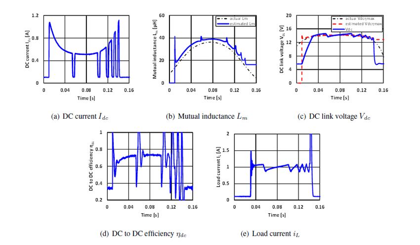
Special Issue - 2019                                                      International Journal of Engineering Research & Technology (IJERT)
                                                                                                                               ISSN: 2278-0181
                                                                                                          RTESIT - 2019 Conference Proceedings

[14]   M. Kato, T. Imura, and Y. Hori, “Study on maximize efficiency by
       secondary side control using DC-DC converter in wireless power
       transfer via magnetic resonant coupling,” in Proc. The 27th
       International Electric Vehicle Symposium and Exhibition (EVS),
       2013, pp. 1–5.
[15]   D. Kobayashi, T. Imura, and Y. Hori, “Real-time coupling
       coefficient estimation and maximum efficiency control on dynamic
       wireless power transfer for electric vehicles,” in Proc. IEEE PELS
       Workshop on Emerging Technologies; Wireless Power, 2015, pp. 1–
       6.

  Volume 7, Issue 08                                           Published by, www.ijert.org                                                 7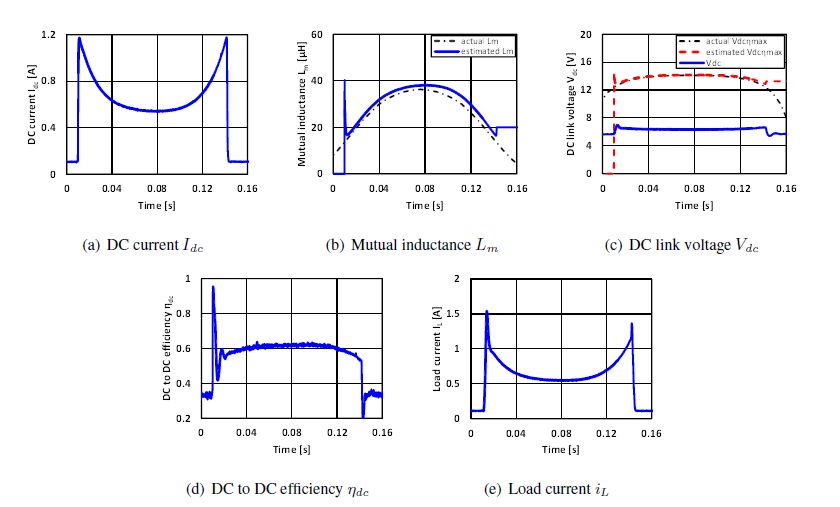
You can also read