WING-R EC & WING-G EC - DESIGN AIR CURTAIN FOR VERTICAL INSTALLATION INDIVIDUAL INNOVATIVE ENERGY-SAVING
←
→
Page content transcription
If your browser does not render page correctly, please read the page content below
WING

       WING-R
    WING
                   WING-R
          WING-G

   WING-G
WING-R EC & WING-G EC
DESIGN AIR CURTAIN
FOR VERTICAL INSTALLATION

INDIVIDUAL
INNOVATIVE
ENERGY-SAVING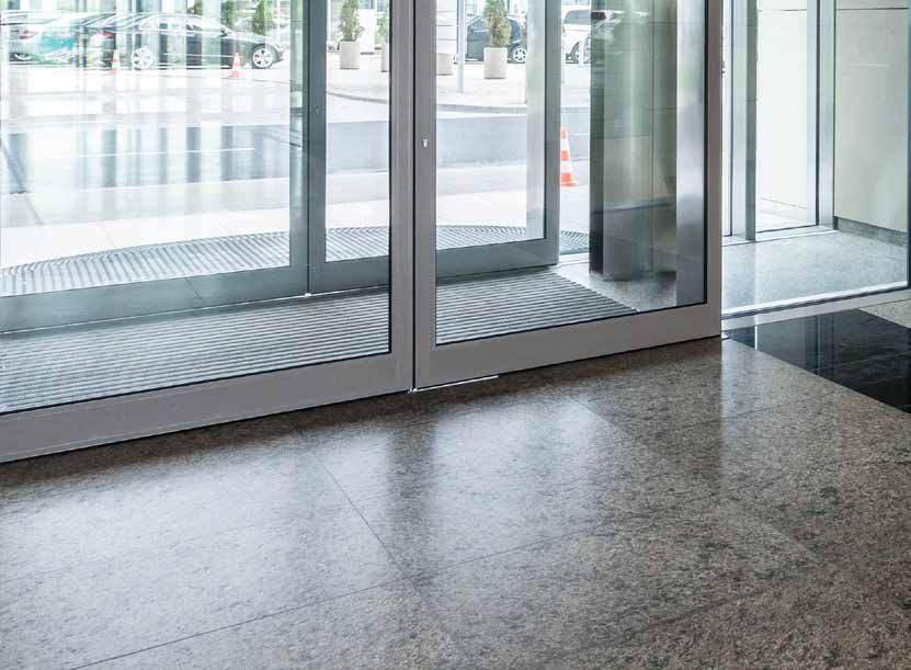
WING-R EC
DESIGN AIR CURTAIN
+Jetflow discharge nozzle + Elegant steel-
patented, steplessly variable composite design
high-quality powder coated
or with stainless steel housing
+ Attractive intake grille
with micro grille behind it
WING-G EC
DESIGN AIR CURTAIN
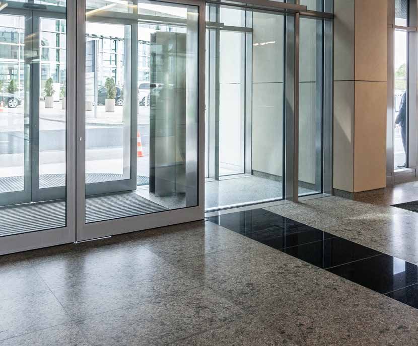
Applications The housing
WING-R EC with a curved design and WING-G EC with a Self-supporting steel/aluminium composite construction with a
straight design are particularly suitable for curved sliding doors, curved or straight design. Screws are not visible. Available with
automatic linear sliding doors as well as for retrofitting to powder coating in a selection of RAL colours, or as a stainless
revolving doors. The timeless design and user-friendly steel version. Aluminium Jetflow discharge nozzle, powder
technology will satisfy architects, planners, clients and operators coated to match the unit. Attractive intake grille with micro grille
in equal measure. WING-R EC and WING-G EC are the ideal behind it (used as an intake filter) for filterless operation.
solution wherever a door air curtain cannot be installed
horizontally due to the particular characteristics of the building, Heating media
or if vertical installation is preferred for aesthetic reasons. Heat exchangers for different heating media
Also ideal for retrofitting. LPHW: For normal temperature LPHW 70/50 °C and low-
temperature LPHW 60/40 °C, other temperatures available on
Special design request.
The height of the unit should be selected individually, depending High-quality heat exchanger made from copper tubes, with
on the height of the entrance or door. As the Jetflow discharge pressed-on, extra-strong aluminium fins.
nozzle runs along the entire length of the unit, the heated air is ELECTRO: 3-stage heat exchanger 400 V, spiral form, corrosion
also blown directly over the floor, where the potential for cold air resistant, with thermal overheating protection and switch-off
to enter is the greatest. The patented and multi-adjustable delay.
(without tools) Jetflow discharge nozzle – with its adaptive,
asymmetrical nozzle cross-section – is characterised by a
smooth air stream and a large throw distance.
2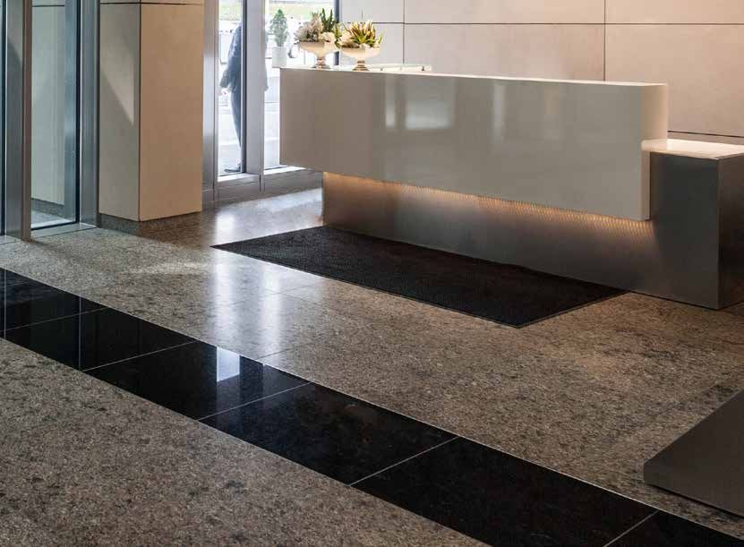
Advantages at a glance
                                             + Made in Germany
                                             + ErP conform / EC fans
                                             + Patented, multi-adjustable Jetflow
                                                   discharge nozzle with adaptive, asym-
                                                   metrical nozzle cross-section
                                                   (large throw distance, low noise,
                                                   optimum shielding)

                                             + Certified by TÜV-Süd
                                             + Self-supporting steel/aluminium com-
                                                   posite construction.
                                                   Screws are not visible.
                                             + Invisible energy supply
                                             + Simple to install
                                             + Individual RAL colours available
                                                   or as stainless steel version
                                             + Different heating media possible
                                             + Individual unit lengths up to 3000 mm

EC fans                                                              Control
The efficiency of the EC fans used by TEKADOOR is > 90%              Electronic TEKADOOR GTC EC control unit, multifunctional
under partial load operation. This is 30–35% higher than for         with touch display, including an optional ModBus interface
conventional AC fans. This does not just increase the efficiency,    A GTC 1 EC control unit is used as standard for models with
but also reduces the operating costs. The individually-driven        LPHW heating. A GTC E EC control unit is used for models
EC fans with integrated motor protection can intake air in both      with electrical heating. The units come with 20 m preassembled
directions. They have vibration-free bearings and are controlled     and shielded data cable. The GTC 1 EC 5-stage control unit
using a PWM signal (pulse width modulation).                         includes the ability to switch from manual to automatic and from
They do not just comply with Directive ErP, but actually exceed      summer mode to winter mode as standard. A solenoid valve of
this standard.                                                       up to 2.5 A can be connected as an option for the winter mode.
                                                                     With the standard GTC E EC control unit, the airflow can be
Mounting                                                             selected manually in 5 stages and the heating capacity – de-
Trouble-free mounting directly on the finished flooring, via holes   pending on the fan level – can be selected manually in 3 stages.
in the floor plate (not visible once installation complete). The     Each control unit includes a manual to automatic mode switch
floor plate has appropriate recesses for invisible energy supply     and a potential-free contact for enabling via any on-site BMS or
from below. Optional: Power supply is also possible from above.      BEMS. A choice of 5-stage or stepless fan operation is offered
                                                                     as standard.
Maintenance                                                          A maximum of 10 units can be connected in parallel.
Easy to clean (micro grille) without opening the unit by simply
vacuuming the intake grille. Discreet inspection panel for
maintenance work, hinged on one side – easy to access from
the room side.

                                                                                                                                  3
WING-R/G EC
DETAILS

Connections                                                       Connection box
Floor mounted vertical unit

Heating connections – flow and return – for easy connection to    Simple electrical connection of the power supply 230 V/50 Hz
the on-site heating system.                                       thanks to the internal connection box.

- Connections: Either from below or above, invisible within the   Exception:
door air curtain.                                                 Electrical units with a heating capacity greater than 22.5 kW.

4

Data cable connection/interface                                     Jetflow discharge nozzle
                                                                    (WING-R)

Standard connection options for the data cable and an optional      Jetflow discharge nozzle with adaptive, asymmetrical nozzle
solenoid valve or thermo-electric shut-off valve within the unit.   cross-section. The special design of this patented discharge
Simple plug and play of the data cable.                             nozzle permits stepless variation of the discharge angle
                                                                    combined with a longer guided, smooth air stream with
Control:                                                            optimum throw distance.
Input for the data cable to the control unit.

Auxiliary:
Output for parallel operation with other units.

                                                                                                                                   5
WING-R EC
DISCHARGE SIDE ACCESS SIDE INTAKE SIDE
Draufsicht Draufsicht Draufsicht
Ausblasseite RevisionsseiteAusblasseite Revisionsseite stehend
Ansaugseite Ausblasseite
LINKS Ansaugseite
Revisionsseitestehend LINKS Ansaugseite stehend LINKS
ø 10 ø 10 ø
OUT OUT OUT
IN ø 50 IN ø 50 IN ø5
connection box connection box conn
inspection panel inspection panel
inspection A inspection Draufsicht A inspectionDraufsicht Draufsicht
A
panel panel
Draufsicht panel stehend RECHTS
stehend RECHTS stehend RECHTS
Ausblasseite Revisionsseite Ansaugseite stehend LINKS
ø 10 ø 10
OUT OUT
ø 50 IN ø 50 IN
connection box ø 10 connection box conne
OUT
inspection panel IN inspection
ø 50 panel inspection panel
130 694 130 290 694 130 290 694 connection290
box Technische Änderungen vorbehalten
Technische Änderungen vorbehalten
223 223 223
PLAN VIEW (STANDING LEFT) PLAN VIEW (STANDING RIGHT)
inspection panel
Draufsicht inspection Draufsicht
augseite A
stehend LINKS panel stehend RECHTS
ø 10 ø 10
OUT OUT
IN ø 50 ø 50 IN
connection box connection box
inspection panel inspection panel
130 Draufsicht 694 290 Technische Änderungen vorbehalten
223
stehend RECHTS
ø 10 * WE RESERVE THE RIGHT TO MAKE TECHNICAL CHANGES
OUT
Connection-ready door air curtainøfor50visible installation
IN as a floor mounted vertical unit, with a curved design.
Ambient air intake is fromconnection
the side, on
boxthe room side.
inspection panel
6 Technische Änderungen vorbehalten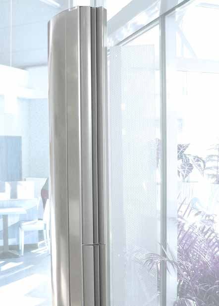
WING-G EC

           ACCESS SIDE                                            INTAKE SIDE                      REAR

                                                                 252         252                   252
                         570               570                   570         610             610                        610

                                                                                                                                                  570                  570
            A                  A                       A
                                                                                                                                              ø 13                  ø 13
                                                                                                                                                           E       IN        E
                                                                                                                                        ø 40                    ø 40

                                                                                                                                                                   OUT

                                                                                                                   40                    40                            40 30 48
                                                 150              150              150                                                         211                    211
                                                                                                                                                 164                    164
                                                                                                                                                   118                     118
                                                                                                                                                    106                     106
                                                                                                                                                       81                      81
                                                                                                                                                      350                     35
                                                                                                                                                      362                     362

           SECTION                   252                          DISCHARGE SIDE                   TOP VIEW

570                                                    610
                                                                                                                                   4 M10 rivet nuts
                                                                                                                                   for wall fixation on site

                               570

                         ø 13
                                     E     IN                         252
                    ø 40                                        202

                                           OUT                                                               570
      40                                         30 48 57 100
                           211                                                                           ø 13
                                                                                                                    E         IN                                252
                             164                                                                     ø 40                                                 202
                               118
                                106                                                                                           OUT
                                   81
                                  350                                                 40                                               30 48 57 100
                   150            362                                                                    211
                                                                                                           164
                                                                                                             118
                                                                                                              106
                                                                             * WE RESERVE THE                    81
                                                                                                     RIGHT TO MAKE            TECHNICAL CHANGES
                                                                                                                350
                                                                                                                362
       Connection-ready door air curtain for visible installation as a floor mounted vertical unit, with a straight design.
       Ambient air intake is from the side, on the room side.

                                                                                                                                                                7
WING-R/G EC
STANDARD CIRCUIT DIAGRAM FOR LPHW
ModBus
interface
Fr 21.09.2018 Room Temp
07:52 10°C
Room temperature. Sensor installed
Heat level Fan level
0/0
Automatic
0/0
Timer
(optional)
Hand off
1 2 3
Magnetic valve
(OPTIONAL) 1 ON
to input (CONTROL) next PCB M
MOD Bus
Address 1-9 1 2 3 4
Standard suppled L N PE
8 shielded datacable
8 (20 m) with next
RJ-45 connectors Fan RJ 45
4
AUXILIAR CONTROL L2 N PE Magnetventil
230V / 50Hz L1
(OPTIONAL)
L2 N PE N zum Steuerteil (CONTROL)
AUX MON intern
PE
Adresse 1-9
Standard
weiss/white imp.
Anschlusskabel
gelb/yellow Y 0-10 V
8 8 (20 m) mit
blau/blue 0V
RJ-45 Stecker
PCB EC rot/red +10 V
CPU AUXILIAR CONTROL
901
78
2 3
F 16 AT
45 6
Address
switch
AUX MON
0 = MASTER
1 - 9 = SLAVE
1 11 2 12 3 13 4 14 5 15 6 16 7 17 8 9 10 18 19 20 L N PE
Connecting box Plati
Frost protection thermostat
Roomtemp. sensor
BMS On/Off
ext. Contact
nicht belegt
Main switch and fuses
Operation
CPU
not used
not used
to be installed by third
fault
parties must comply
q to all applicable rules and 901
3
requirements!
78
2 3
45 6
optional
optional
optional
230V/ 50Hz
Adress
Schalter
0 TECHNICAL
* WE RESERVE THE RIGHT TO MAKE = MASTER
CHANGES
1 - 9 = SLAVE
Technical changes reserved
Name Datum
CONTROL UNIT GTC 1 EC
gezeichnet/signet la 02.01.2019
Multilingual, menu-driven electronic control unit for TEKADOOR 1 11 2 air12curtains
3 13with
4 LPHW
14 5 heating
15 6 and16 7 17 8
Werkstoff Maßstab
Frostschutzthermostat
energy-saving EC fans. A standard feature of the control unit with touch display is a choice between
5-stage or stageless
Pos.
fan control,
von
which canTbe
Gruppe eile
selected individually by the operator. The relevant
ext. Signalgeber
DDC- Freigabe
operatingNr.:
Kundenzeichnung modes and symbols are arranged clearly on the colour display. The date, time and room
Erstelldatum
temperature are shown as standard. The room temperature is monitored via an internal temperature
nicht belegt
nicht belegt
nicht belegt
nicht belegt
sensor inGTC I EC
unit as190102
Benennung
Name
Kunde
the control standard. Blatt
1 von 1
An easy-to-navigate menu offers a selection of different operating modes:
Hand – manual operation
Auto AS – automatic operation via cool down protection
Auto RT – automatic operation via room temperature
Auto TK – automatic operation via door contact
Auto Kombi – option to combine all individual automatic modes
optional
optional
optional
An enabling contact and potential-free operation and malfunction signals are provided for control via
an on-site BMS or BEMS. Errors and faults are displayed with a red „warning“ sign. By coding the
control boards differently, up to 10 door air curtains can also be operated in parallel with 1 control unit,
using the Master/Slave principle. The control board is preinstalled in the door air curtain unit and 20 m
of preassembled data cable (connection between the door air curtainName and control unit)
Datum are included as
gezeichnet/signet la 07.03.2017
standard.
8 Werkstoff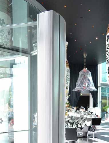
WING-R/G EC
CIRCUIT DIAGRAM ELECT. HEAT EXCHANGER
Fr 21.09.2018 Room Temp
ModBus
Room temperature. Sensor installed interface
07:52 10°C
Heat level Fan level
(optional)
0/0 0/0
Automatic Timer
Hand off
K1 K2 K3 1 2 3
1
to input M ON
Standard supplied q
MOD Bus
CONTROL shielded datacable S 60°
next PCB (20 m)
1 2 3 4
K1
8 1:1 straight wired next
RJ-45 Stecker K1 Fan
q q q
RJ 45
8 S 80° S 45° S 50°
4
AUXILIAR CONTROL L2 N PE
Magnetventil
230V / 50Hz L1 (OPTIONAL)
L2 N PE N
zum
PE Steuerteil (CONTROL)
AUX MON intern
Adresse 1-9
weiss/white imp. Standard
Anschlusskabel
8
gelb/yellow YPWM
blau/blue 0V
8 (20 m) mit
rot/red +10 V
RJ-45 Stecker
CPU F 16 AT
901 PCB EC
78
2 3
45 6
AUXILIAR CONTROL
Adress
switch
0 = MASTER
1 - 9 = SLAVE q
S 100°
AUX MON
1 11 2 12 3 13 4 14 5 15 6 16 7 17 8 9 10 18 19 20
Blow out Temp sensor
1 2 3 L N PE
K0
Room Temp sensor
Frost thermostat
BMS On/Off
Connecting box
Plati
ext. Signal
Operation
Failure
free
free
q q
K3 K2
4 3
CPU
3~400V/ 50Hz
optional
optional
optional
230V/ 50Hz 901
78
2 3
Mains switch and fuses 45 6
to be installed by third
step 2 step 1 parties must comply
step 3 = step 1 + step 2 to all applicable rules and Adress
requirements! Schalter
* WE RESERVE THE RIGHT TO 0
MAKE = TECHNICAL
MASTER CHANGES
Technical changes reserved 1 - 9 = SLAVE
Name Datum
gezeichnet/signet Sa 02.01.2019 CONTROL UNIT GTC E EC
Werkstoff
1 11 2 air
Maßstab
Multilingual, menu-driven electronic control unit for TEKADOOR 12curtains
3 13 with
4 LPHW
14 5 heating
15 6 and16 7 17 8
Frostschutzthermostat
energy-saving Pos. EC fans. 5-stage
von
fan operation
Gruppe or stageless fan control – easy to adjust on the control unit
Teile
using the touch
Kundenzeichnung Nr.: display. The electric heater can be activated in 3 stages.The relevant operating modes
Erstelldatum
ext. Signalgeber
DDC- Freigabe
and symbols are arranged clearly on the colour display. The date, time and room temperature are shown
Benennung
as GTC
standard. The E EC
room UK 190201
temperature is monitored via an internal temperature sensor in the control unit as
nicht belegt
nicht belegt
nicht belegt
nicht belegt
Name
Kunde Blatt
standard. 1 von 1
An easy-to-navigate menu offers a selection of different operating modes:
Hand – manual operation
Auto AS – automatic operation via cool down protection
Auto RT – automatic operation via room temperature
Auto TK – automatic operation via door contact
Auto AT – automatic operation via constant discharge temperature
Auto Kombi – option to combine all individual automatic modes
optional
optional
optional
An enabling contact and potential-free operation and malfunction signals are provided for control via an
on-site BMS or BEMS. A constant discharge temperature can be set via an optional cable temperature
sensor. This enables optimisation of the shielding performance. A week timer is incorporated as standard,
enabling up to 12 different switching times to be programmed per week. Errors and faults are displayed
with a red „warning“ sign. By coding the control boards differently, up to 10 door air curtains can also be
operated in parallel with 1 control unit, using the Master/Slave principle.The Name control board is preinstalled in
Datum
gezeichnet/signet la 07.03.2017
the door air curtain unit and 20 m of preassembled data cable (connection between
the door air curtain and control unit) are included as standard. 9
Werkstoff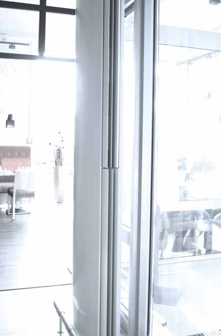
WING-R/G EC
   OPTIONAL ACCESSORIES

Thermostatic                         Solenoid valve                          Thermo-electric                    Ceiling attachment
straight-way valve                                                           shut-off valve                     set

(Setting range + 20 °C to + 35 °C)   Opens or closes the warm water          230 V / 50 Hz, normally closed.
limits the discharge temperature     circuit in the summer/winter            On-site installation in the        For problem-free, vibration free
(constant supply air temperature     setting of the control unit, in order   heating flow. Actuated by          ceiling attachment, consisting
limitation). Also available as a     to close the heating water circuit      the summer/ winter circuit.        of M8 or M10 threaded rods,
3-way valve.                         and save energy during summer           Summer function – closed. Winter   up to 1000 mm length, vibration
                                     operation or when the air curtain       function – opened.                 dampers, turnbuckles and coun-
                                     is not working (normally closed).                                          ter nuts.
                                     Caution: If solenoid valves are
                                     used, it is expressly recommend-
                                     ed to install a frost protection
                                     thermostat (automatically actuat-
                                     ed) and a strainer.

    10
Frost protection Control unit Electronic Door contact
thermostat GTC 2 EC control valve solenoid switch
For monitoring LPHW heat Possibility of combination of Electronic valve with 0-10V im- In automatic mode switches on
exchangers exposed to the risk various automatic operations. pulse and blow-out temperature the door air curtain in the
of frost. As soon as the temper- A constant discharge tempera- sensor completely installed and preselected stage
ature falls below +7 °C, the fans ture can be set via an optional wired. In combi-
are switched off and an optional electronic control valve, and a nation with the GTC 2 control, a
solenoid valve is opened. week timer is incorporated as preselected blow-out tempera-
standard, enabling up to 12 ture is kept constant.
different switching times to be
programmed per week.
11WING-R/G EC TECHNICAL DATA 12
WING-R EC 2000
TECHNICAL DATA

Design based on:                                                           recommended operating point
                                                                        intake temperature tLE = +20 °C
                                                                    discharge temperature tLA = +34 °C
                                                                          throw distance = up to 2.50 m

WING-R EC 2000                                            2002                2002.5               2003

Air quantity max.                             m3/h        2700                 3600                4500

Heating capacity        LPHW 70 / 50 °C        kW          12.7                17.0                21.2
rated1                  LPHW 60 / 40 °C        kW          12.7                17.0                21.2

Flow rate               LPHW 70 / 50 °C       m3/h         0.56                0.75                0.93
                        LPHW 60 / 40 °C       m /h
                                                3
                                                           0.55                0.74                0.92

Water resistance        LPHW 70 / 50 °C        kPa         5.7                  2.4                3.2
                        LPHW 60 / 40 °C        kPa         7.0                  4.5                3.2

Nominal connection      Internal thread       Inches     2 x 3/4"             2 x 3/4"           2 x 3/4"
sizes                   Flow/return            DN           20                  20                  20

EC fans                 Voltage                 V                         230 / 1 / N / PE
                        Frequency              Hz                               50
                        Current consumption     A          3.1                  4.1                5.1
                        Motor power            kW          0.5                  0.6                0.8

Electric heater         Voltage                 V                         400 / 3 / N / PE
3-stage                 Frequency              Hz                               50
                        Heating capacity       kW         4/8/12             6/12/18             6/12/18

Sound pressure level2   Highest setting       dB(A)         59                  60                  61

Drawing dimension       Unit height (A)        mm         2000                 2500                3000
                        Unit depth             mm          290                  290                290
                        Unit width             mm          670                  670                670

Weight                                         kg           70                  90                 100
                                                       * WE RESERVE THE RIGHT TO MAKE TECHNICAL CHANGES

1. Rated operation based on operating point (see above), discharge temperature control recommended.
2. Measured at a lateral distance of 3 m. Sound pressure level may very depending on surrounding conditions.

A well-balanced pressure ratio is one of the prerequisites for perfect function.

                                                                                                            13
WING-G EC 2000
TECHNICAL DATA
Design based on: recommended operating point
intake temperature tLE = +20 °C
discharge temperature tLA = +34 °C
throw distance = up to 2.70 m
WING-G EC 2000 2002 2002.5 2003
Air quantity max. m3/h 3600 4500 5400
Heating capacity rated1 LPHW 70 / 50 °C kW 17.0 21.2 25.5
LPHW 60 / 40 °C kW 17.0 21.2 25.5
Flow rate LPHW 70 / 50 °C m3/h 0.75 0.93 1.30
LPHW 60 / 40 °C m /h
3
0.74 0.92 1.29
Water resistance LPHW 70 / 50 °C kPa 2.4 3.2 4.1
LPHW 60 / 40 °C kPa 4.5 3.2 4.2
Nominal connection Internal thread Inches 2 x 3/4" 2 x 3/4" 2 x 3/4"
sizes Flow/return DN 20 20 20
EC fans Voltage V 230 / 1 / N / PE
Frequency Hz 50
Current consumption A 4.1 5.1 7.2
Motor power kW 0.6 0.8 0.9
Electric heater Voltage V 400 / 3 / N / PE
3-stage Frequency Hz 50
Heating capacity kW 6/12/18 6/12/18 10/20/30
Sound pressure level2 Highest setting dB(A) 60 61 62
Drawing dimension Unit height (A) mm 2000 2500 3000
Unit depth mm 252 252 252
Unit width mm 610 610 610
Weight kg 90 100 134
* WE RESERVE THE RIGHT TO MAKE TECHNICAL CHANGES
1. Rated operation based on operating point (see above), discharge temperature control recommended.
2. Measured at a lateral distance of 3 m. Sound pressure level may very depending on surrounding conditions.
A well-balanced pressure ratio is one of the prerequisites for perfect function.
14WING-G EC 3000
TECHNICAL DATA
Design based on: recommended operating point
intake temperature tLE = +20 °C
discharge temperature tLA = +34 °C
throw distance = up to 3.00 m
WING-G EC 3000 3002 3002.5 3003
Air quantity max. m3/h 5400 6300 7200
Heating capacity rated1 LPHW 70 / 50 °C kW 25.5 29.7 34.0
LPHW 60 / 40 °C kW 25.5 29.7 34.0
Flow rate LPHW 70 / 50 °C m3/h 1.11 1.31 1.49
LPHW 60 / 40 °C m /h
3
1.11 1.31 1.49
Water resistance LPHW 70 / 50 °C kPa 3.7 5.2 7.2
LPHW 60 / 40 °C kPa 4.2 6.1 7.2
Nominal connection Internal thread Inches 2 x 3/4" 2 x 3/4" 2 x 3/4"
sizes Flow/return DN 20 20 20
EC fans Voltage V 230 / 1 / N / PE
Frequency Hz 50
Current consumption A 6.2 7.2 8.2
Motor power kW 0.9 1.1 1.2
Electric heater Voltage V 400 / 3 / N / PE
3-stage Frequency Hz 50
Heating capacity kW 10/20/30 10.7/21.4/32 10.7/21.4/32
Sound pressure level2 Highest setting dB(A) 62 63 64
Drawing dimension Unit height (A) mm 2000 2500 3000
Unit depth mm 252 252 252
Unit width mm 610 610 610
Weight kg 103 135 145
* WE RESERVE THE RIGHT TO MAKE TECHNICAL CHANGES
1. Rated operation based on operating point (see above), discharge temperature control recommended.
2. Measured at a lateral distance of 3 m. Sound pressure level may very depending on surrounding conditions.
A well-balanced pressure ratio is one of the prerequisites for perfect function.
15www.TEKADOOR.de
German headquarters
TEKADOOR GmbH
Albert-Einstein-Str. 11
D-40764 Langenfeld
T. +49 (0) 2173 - 20766-0
F. +49 (0) 2173 - 20766-111
E. info@tekadoor.de
A = 01.07.2019You can also read


