Treatment of Under-depth Underground Wiring Systems (UWS) in Brownfield Installations - Technical Note 159
←
→
Page content transcription
If your browser does not render page correctly, please read the page content below
Technical Note 159

Treatment of Under-depth Underground Wiring Systems
(UWS) in Brownfield Installations
November 2020
Copyright
© The State of Queensland (Department of Transport and Main Roads) 2020.

Licence

This work is licensed by the State of Queensland (Department of Transport and Main Roads) under
a Creative Commons Attribution (CC BY) 4.0 International licence.

CC BY licence summary statement
In essence, you are free to copy, communicate and adapt this work, as long as you attribute the
work to the State of Queensland (Department of Transport and Main Roads). To view a copy of this
licence, visit: https://creativecommons.org/licenses/by/4.0/

Translating and interpreting assistance
              The Queensland Government is committed to providing accessible services to
              Queenslanders from all cultural and linguistic backgrounds. If you have difficulty
              understanding this publication and need a translator, please call the Translating and
              Interpreting Service (TIS National) on 13 14 50 and ask them to telephone the
              Queensland Department of Transport and Main Roads on 13 74 68.

Disclaimer
While every care has been taken in preparing this publication, the State of Queensland accepts no
responsibility for decisions or actions taken as a result of any data, information, statement or
advice, expressed or implied, contained within. To the best of our knowledge, the content was
correct at the time of publishing.

Feedback
Please send your feedback regarding this document to: tmr.techdocs@tmr.qld.gov.au

Technical Note, Transport and Main Roads, November 2020
TN159 Treatment of Under-depth Underground Wiring Systems (UWS) in Brownfield Installations 1 Background The Department of Transport and Main Roads standards specify compliance and minimum depth requirements for underground wiring systems (UWSs) to ensure durability in the installation environment or protection against inadvertent damage due to manual or mechanical excavation work. UWSs that does not meet the depth requirements are deemed 'under-depth'. This document is intended for inspectors and project managers who have identified legacy or brownfield installation sites that do not meet the minimum UWS depth requirements and may pose an electrical safety risk to any third parties who would undertake manual or mechanical excavation work in the vicinity of those sites. It is necessary to mitigate those risks by prescribing treatments which will render those sites compliant with the expressed intent of the department’s requirements. Third parties who are unsure about the existence of an underground electrical cable should always seek advice by contacting the relevant Transport and Main Roads District for underground cable location information, before excavation. Obtaining accurate information about a work site significantly minimises the risks for injury, personal liability and death. This Technical Note is not an exhaustive list of all safety matters that need to be considered. In many instances, it may be cost-prohibitive to replace the entire underground wiring system to ensure compliance. A suitable alternative approach would be to identify portions or segments within an installation likely to be subjected to manual or mechanical excavation work and then apply the relevant treatment to the identified segments such that the installation becomes compliant by specific design as outlined in Clause 1.9.4 of AS /NZS 3000 Electrical installations (known as the Australian / New Zealand Wiring Rules). 2 Scope This Technical Note applies to the treatment of under-depth or non-compliant UWSs in brownfield sites for non-compliances associated with underground conductors. Such installations should comply with the department’s Standard Drawings SD1149 and SD1421 which are based on the Category A conduit type (a) (heavy duty conduit) wiring system as described in Part 2 of AS / NZS 3000. Brownfield installations with UWSs that, due to practical reasons, could not meet the department’s requirements, shall meet the requirements for compliance by specific design as outlined in Clause 1.9.4 of AS / NZS 3000. Although this Technical Note provides some recommendations based on the Queensland Electrical Safety Code of Practice, it is the responsibility of the District's Principal Representative to ensure compliance with the department’s requirements or Part 1 of AS / NZS 3000. This Technical Note applies to UWSs installed in the department’s road network but excludes UWSs installed within the confines of a building. This Technical Note does not apply to UWSs for greenfield sites, neither does it apply to UWS installed as part of a project and which are still under warranty. Such installations are not considered brownfield sites. Any non-compliances in such installations shall be remedied to the department’s standards as per the provisions of contract. Technical Note, Transport and Main Roads, November 2020 1
TN159 Treatment of Under-depth Underground Wiring Systems (UWS) in Brownfield Installations

3     Referenced documents
3.1       The Department of Transport and Main Roads Standard Drawings applicable to
          conduit installation

      •    SD 1149 – Traffic signals / Road lighting / ITS – Installation of underground electrical and
           communications conduit

      •    SD 1380 – Road lighting – Slip base pole and footing installation details for no crossfall

      •    SD 1381 – Road lighting – Slip base pole and footing installation details for crossfalls up to
           and including 1:6

      •    SD 1382 – Road lighting pole – Slip base pole and footing installation details for crossfalls
           greater than 1:6 up to and including 1:3

      •    SD 1392 – Road lighting – Base plate mounted pole and footing installation details for
           crossfalls up to and including 1:2

      •    SD 1393 – Road lighting – Base plate mounted pole and footing installation details for
           crossfalls greater than 1:2

      •    SD 1396 – Traffic signals / Road lighting – Joint use traffic signal and road lighting pole and
           footing installation details

      •    SD 1403 – Traffic signals – Mast arm footing installation details, and

      •    SD 1429 – Road lighting – Slip base pole and footing installation details for crossfalls greater
           than 1:6 up to and including 1:3 using concrete step tread.

3.2       Legislation and Standards

      •    AS /NZS 3000 Electrical installations (known as the Australian/New Zealand Wiring Rules)

      •    AS/NZS 2648.1 Underground marking tape – Non-detectable tape

      •    Queensland Electrical Safety Code of Practice 2020 – Works – (Electrical Safety Office)

      •    Electrical Safety Act 2002 – (Electrical Safety Office)

      •    Electrical Safety Regulation 2013 – (Electrical Safety Office).

4     Identifying sites for treatment
Any site with an under-depth electrical LV conduit poses a potential electrical safety risk to
third parties who would undertake manual or mechanical excavation work at the site; however, the risk
is different from site to site as it depends on the extent of under-depth as well as the likelihood of
excavation works being carried at the site. It is the responsibility of the District's’ Principal
Representative to determine these risks for their site and select the appropriate method of treatment
as prescribed in Section 5.

4.1       Selection of sites or portions to be treated
Once the entire under-depth conduits on the site have been identified, the extent of treatment should
be determined. Main options include:

      •    treatment of entire under-depth conduit installation, or

      •    treatment of a segment of the under-depth conduit installation based on site risk analysis.

Technical Note, Transport and Main Roads, November 2020                                                       2
TN159 Treatment of Under-depth Underground Wiring Systems (UWS) in Brownfield Installations
4.2 Risk analysis
To determine the risk for each site, the type of hazard, the likelihood of the hazardous event, and the
consequence of the hazard must be carefully considered. These three items are discussed below in
the context of under-depth conduits as a guide.
4.2.1 Site hazard
The obvious hazard associated with under-depth electrical UWSs is that it may result in persons
excavating at the site coming into contact with live electrical wires and receiving electrical shock. This
hazard will determine the level of risk associated with the treatment of a site. The Principal
Representative may outline additional hazards to be considered in the risk analysis.
4.2.2 Likelihood
The likelihood of a hazard, such as, an excavator or other equipment coming into contact with live wire
at the site depends on:
• the UWS site location
• the UWS depth, and
• other features of the site to be determined by the District's Principal Representative.
The UWS site location may be one that no development works are expected or it may be a busy
intersection or an area with development proposals which may mean excavations for other services
are likely.
The UWS depth may range from a few millimetres, meaning higher risk, to half a metre where the
likelihood of the hazard is reduced. Both factors must be included in determining the likelihood. The
District’s Principal Representative may consider some brownfield UWSs may not strictly comply with
the department’s standards but may still comply with the broader Australian Standard, which could be
a risk mitigating factor.
The likelihood shall be allocated in accordance with the Department of Transport and Main Roads
Risk Matrix (available on request by email to Elec_Infrastructure_Approvals@tmr.qld.gov.au).
4.2.3 Consequence
An excavator or other equipment coming into contact with live wire at the site may result in injury,
personal liability or even death; therefore, the consequence of such an event is always classified as
severe.
4.2.4 Risk characterisation
The departmental Risk Matrix shall be used for the risk analysis of the aforementioned hazards. The
aim should always be to introduce treatments that result in reduced risk; that is, 'medium' or 'low' from
an initial default of 'Extreme' or 'High'.
Technical Note, Transport and Main Roads, November 2020 3TN159 Treatment of Under-depth Underground Wiring Systems (UWS) in Brownfield Installations
5 Treatment process
5.1 Identifying the problem
This is the first step in resolving the non-compliant UWS in a given site location. Typical items to
consider include:
• conduit type (heavy duty (HD), medium duty (MD) and so on)
• the depth (mm) of the conduit at the site in question
• the thickness (mm) of concrete, if any, above the conduit
• the likelihood of an excavation work being carried out at the site by other parties (see
Section 4.2.2), and
• whether the UWS is under trafficable area or carriageway.
5.2 Treatment options for conduits under footways or islands
Where possible, all non-compliant UWSs under footways or islands must be made compliant to the
department’s Standard Drawings SD 1149 and SD 1421, followed by appropriate labelling.
The main non-compliance addressed by this document is under-depth UWS; however, the type of
conduit is an important feature as it affects depth specification and is also a determining factor in
achieving compliance with the department’s Standard Drawings SD 1149 and SD 1421 which strictly
specify Category A UWS (or HD conduits).
Where it is not possible to achieve compliance with the department’s Standard Drawings SD 1149 and
SD 1421, other treatment options that would mitigate the electrical risk must be considered, such as
compliance with AS /NZS 3000 Part 2. For brownfield sites, remediation to UWS that meet Category A
or B of AS /NZS 3000 should be considered as a viable option. The treatment options are as shown in
Figure 5.2.
Technical Note, Transport and Main Roads, November 2020 4TN159 Treatment of Under-depth Underground Wiring Systems (UWS) in Brownfield Installations
Figure 5.2 – Brownfield under-depth underground wiring systems treatment overall process
Nature of non-compliance
• Conduit type
• Conduit depth(mm)
• Concrete thickness (mm), if any
• Likelihood of excavation
• Whether UWS is under trafficable area or
carriageway.
• Others
Is the non-compliant UWS under a
Yes
carriageway or road-crossings (see 5.3)?
No
Possible to remedy to
TMR standards?
No Yes
Possible to remedy to Remedy to
No category A or B UWS of Yes TMR standard
Remedy to TMR AS3000? (see 5.2.1)
standard
OR
Minimum cover and
mechanical protection
to be equivalent to
IS conduit
section 4.4.2 of the No
HD?
QLD Electrical Safety Remedy to
Code of Practice and AS3000 part 2
meet Part 1 of AS3000, Yes (see 5.2.1)
endorsed/certified by
a pavement engineer
RPEQ Alternative
treatment (see
5.2.2)
B
Surface Label
(see 5.4.2)
Document the
solution and place
in a folder at site
Technical Note, Transport and Main Roads, November 2020 5TN159 Treatment of Under-depth Underground Wiring Systems (UWS) in Brownfield Installations
5.2.1 Remediation to departmental Standard Drawings or AS /NZS 3000 Part 2
For a UWS to meet to the Department of Transport and Main Roads Standard Drawings listed in
Section 3.1 (particularly SD 1149 and SD 1421), it must satisfy the following:
• the conduit must be heavy duty (HD), and
• the depth of the conduit must be as described in Table 5.2.1.
If the HD conduit depth does not meet the 600 mm requirement in Table 5.2.1, but exceeds a 500 mm
depth, it is deemed to comply with AS /NZS 3000 Part 2, without surface covering. For HD conduit
depth exceeding 500 mm for brownfield installations, no remedial action is required.
Remediation to UWS that meet Category A or B of AS /NZS 3000 is acceptable for brownfield sites.
The Contractor shall develop a process that will transition the non-compliant UWS to a
remediated UWS compliant with the department’s Standard Drawings.
The remediation process must be followed by appropriate site labelling, where applicable, and also
documentation of the adopted method.
Table 5.2.1 – Underground wiring system – minimum depth of cover
Covering on surface of ground above Transport and Main Roads Standard Drawings
wiring system SD 1149, SD 1421 and AS /NZS 3000 –
minimum depth of cover
Poured concrete of 75 mm minimum thickness 300 mm
No surface covering or less than 75 mm 600 mm (Transport and Main Roads) or
thickness of concrete 500 mm (AS 3000)
5.2.2 Alternative treatment
Where it is impossible to remedy an under-depth conduit to comply with the department’s Standard
Drawings or the Queensland Electrical Safety Code of Practice, an alternative treatment must be
implemented. Section 4.4.2 of the Queensland Electrical Safety Code of Practice states:
Where physical obstructions such as other services make it impossible to achieve these
depths, additional mechanical protection should be provided by means of a minimum cover of
100 mm of 20 MPa concrete or equivalent. Any additional mechanical protection should be
marked with the words electric cable or similar along its length.
The alternative process and associated details are shown in Figure 5.3(a) and Figure 5.3(b).
The remediation process must include appropriate site labelling. Details of the treatment method must
also be documented and the documents kept at a suitable location on site, preferably in the electrical
switchboard, traffic signal controller or Intelligent Transport System (ITS) cabinet as appropriate.
Technical Note, Transport and Main Roads, November 2020 6TN159 Treatment of Under-depth Underground Wiring Systems (UWS) in Brownfield Installations
Table 5.2.2 – Treatment options for heavy duty electrical conduits under footways or islands
for brownfield sites
Non-compliant depth Description of Recommended treatment
non-compliance
500 mm < depth < 600 mm Does not meet Transport and Meets AS /NZS 3000 Part 2; no
Main Roads standards, but further action required
meets AS /NZS 3000
375 mm < depth < 500 mm Meets neither Transport and Overlay 75 mm concrete to meet
Main Roads standards nor Transport and Main Roads
AS /NZS 3000 standards / AS /NZS 3000 Part 2
200 mm < depth < 375 mm Meets neither Transport and If not possible to comply with
Main Roads standards nor Transport and Main Roads
AS /NZS 3000 standards or AS /NZS 3000,
apply alternative remedy; see
Section 5.2.2.
depth < 200 mm Meets neither Transport and If not possible to comply with
Main Roads standards nor Transport and Main Roads
AS /NZS 3000 standards or AS /NZS 3000,
apply minimum cover and
mechanical protection to be
equivalent to Section 4.4.2 of the
Queensland Electrical Safety
Code of Practice and meet Part 1
of AS /NZS 3000– refer
Section 5.2.4. Design to be
endorsed / certified by Electrical
and Structural RPEQ engineer /s
as appropriate.
5.2.3 Mechanical protection
5.2.3.1 Reinforced concrete
The concrete cover for the alternative treatment shall be N25 / 20 and of minimum thickness 125 mm,
reinforced by SL 81 steel mesh.
5.2.3.2 Bedding sand and Type 2 filling
The bedding sand and Type 2 filling are as specified in Standard Drawing SD 1149.
5.2.4 Equivalent mechanical protection
Where the conduit depth is below 200 mm, a mechanical protection equivalent to the intended practice
in the Queensland Electrical Safety Code of Practice and compliant with Part 1 of AS /NZS 3000 shall
be proposed and submitted to the Principal Representative for approval.
5.3 Treatment of underground wiring systems under carriageways or road-crossing
Under-depth UWS beneath trafficable surfaces, carriageways or road crossings shall be remedied to
comply with the department’s Standard Drawing SD 1149. If compliance with the departmental
standards is not possible, a minimum cover and mechanical protection equivalent to Section 4.4.2 of
the Queensland Electrical Safety Code of Practice and meet Part 1 of AS /NZS 3000 shall be applied.
Any applied treatment shall be endorsed / certified by a Pavement, Structural and / or Electrical
RPEQ Engineer, as appropriate.
Technical Note, Transport and Main Roads, November 2020 7TN159 Treatment of Under-depth Underground Wiring Systems (UWS) in Brownfield Installations
Figure 5.3(a) – Alternative treatment process (to be read in conjunction with Figure 5.2)
B
NO
Is conduit depth > 200mm
YES
Excavate to expose
conduit and clear
space for bedding
Bedding sand 75mm
below conduit where
possible
Fill bedding sand to at
least 50mm above
conduit
Type 2 filling material
25mm
Place Marker Tape
Further Type 2 filling
material up to 125mm
below ground level
Pour N25/20 concrete
reinforced with SL81 steel
mesh to ground surface
Minimum cover and mechanical (125mm)
protection to be equivalent to section
4.4.2 of the QLD Electrical Safety Code
of Practice and meet Part 1 of AS3000 –
Place E marker every
refer section 5.2.4. Design to be
500mm as per Standard
endorsed/certified by Electrical and
Drawing SD1149
Structural RPEQ engineer/s
Technical Note, Transport and Main Roads, November 2020 8TN159 Treatment of Under-depth Underground Wiring Systems (UWS) in Brownfield Installations
Figure 5.3(b) – Alternative treatment detail (not to scale)
N25/20 concrete 125mm
reinforced with SL81
steel mesh
Type 2 Filling
D>200mm
Marker Tape
d≥50mm
Bedding Sand
Conduit
5.4 Labelling
Throughout the remediation process as shown in Figure 5.2 and Figure 5.3(a), labelling has been
prescribed as an additional measure to alert other parties of the existence of an electrical service. The
two types of labels are underground and above-ground labels / markers.
5.4.1 Underground markers
Underground labels shall be in the form of marker tapes compliant with AS/NZS 2648.1. The marker
tape shall be placed within the Type 2 filling substrate, preferably midway between the top of the
conduit and the ground surface.
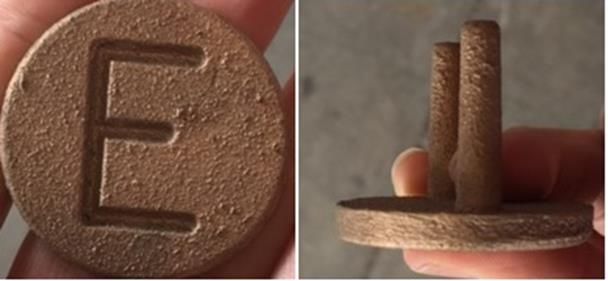
5.4.2 Ground surface labels
E-marker (Figure 5.4.2) labels shall be used to alert other parties of the existence of underground
electrical conduits. These labels shall be placed in accordance with SD 1149. Where new concrete is
applied, additional marking with the words electric cable or similar may be stamped along the length of
the concrete.
Figure 5.4.2 – Brass E-markers
5.5 Documentation
Once the treatment process is completed, the Contractor shall provide detailed documentation of the
solution certifying compliance with the applicable standards and guidelines. Such documentation shall
Technical Note, Transport and Main Roads, November 2020 9TN159 Treatment of Under-depth Underground Wiring Systems (UWS) in Brownfield Installations
be retained by the Designer and also onsite at the electrical installation by the person with overall
responsibility for the installation.
5.5.1 Compliance with the department’s standard
Where remedy to the department’s standards are adopted, the following shall be provided:
• the original non-compliance, and
• how compliance with the department’s standards and this Technical Note have been
achieved.
5.5.2 Compliance with Part 1 of AS /NZS 3000
Where an alternative treatment to the department’s standard was adopted, the following shall be
provided:
• a detailed description of the non-compliance in question
• the Contractor’s acknowledgment as to any departure from the department’s standards or
Part 2 of AS /NZS 3000
• how compliance with Part 1 of AS /NZS 3000 and Section 4.4.2 of the Queensland Electrical
Safety Code of Practice or equivalent is being achieved
• any requirements where the design requires specific installation use by the owner or operator
of the electrical installation and a copy of these requirements for the owner or operator
• the verification undertaken to ensure full compliance with Part 1 of AS /NZS 3000 and the
Queensland Electrical Safety Code of Practice, and the results of this verification, and
• certification of the design by a competent person. Clause 1.4.30 of AS /NZS 3000 defines a
competent person.
6 Earth rods
The standard length for an earth rod installed in a dedicated earth pit is 1.5 m.
In some existing installations where a combined electrical and earth pit was used, the 1.5 m rod was
too short to be worked on safely in a larger pit, and an earth rod of length 1.8 m was used instead. For
replacement of such rod, an earth rod of length 1.8 m must be used.
If an existing earth rod is found to be damaged or corroded, it must be replaced with a 316 stainless
steel equivalent.
Technical Note, Transport and Main Roads, November 2020 10You can also read