OSCAR-III Treatment System Design Manual - March 2019, WA Lowridge Onsite Technologies - Lowridge Tech Onsite ...
←
→
Page content transcription
If your browser does not render page correctly, please read the page content below

OSCAR-III Treatment System Design Manual
             March 2019, WA

               Manufactured by:

        Lowridge Onsite Technologies
                  PO Box 1179
            Lake Stevens, WA 98258
                 877 476-8823
             info@lowridgetech.com

                                           !1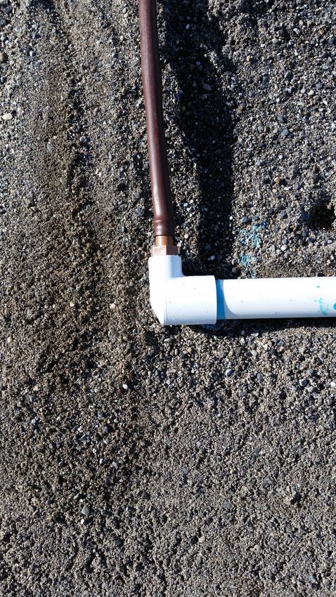
OSCAR-II-Tanks
                                     Length

                         SEE HYDRAULIC LAYOUT ATTACHED

     Width

                                                                            3

                                                                      S5

                                                           S2
                                                                           1

                                                                      S4

                                                                2
                                                                S3
                                                                                S1

                                                                                             PLAN VIEW

               1000 Gallon
               1500 gallon                      1000 Gallon Pre-cast Concrete
             Treatment Vessel                 Single Compartment Discharge Tank
              Treatment Vessel

!2
                                                                       KS
                                                                     OR
                                                                W

                                                                                     UNION
                                                             AD
                                                           HE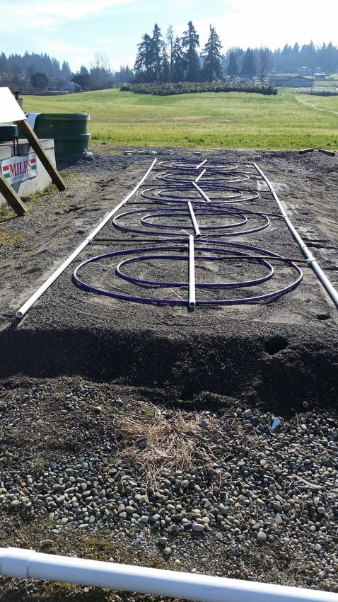
Introduction:
       The OSCAR-III is an onsite sewage treatment and dispersal component for
use with residential wastewater. Wastewater first passes through a treatment
vessel and then into a dosing tank where it is dosed to the OSCAR coils. Effluent is
micro dosed into a layer of ASTM C-33 sand where physical, biological, and
chemical treatment processes remove organic compounds and pathogens from the
waste stream. Treated liquid then migrates downward to the receiving soil where
final discharge of treated wastewater enters the soil environment.
       The OSCAR-III is comprised of a 12” layer of C-33 sand media and a series of
custom manufactured Netafim Bioline drip tubing coils. The sand media is placed
on a prepared soil surface creating a level surface for the coils. OSCAR-III coils are
then placed on the sand media and then covered with another 6” of sand media.
No other cover material is needed. To control erosion or inadvertent disturbance
from children or animals the sand can be covered with jute mat or cover with a
shallow layer of mineral soil. Another option is to spread straw over final cover
until vegetative cover takes hold: plant grass seed or other ground cover as soon as
possible. See appendix “H” for more details.
       The sand/soil interface is the discharge point of the treated wastewater.
Vertical separation is measured from the original soil surface prior to basal area
preparation and the restrictive layer. If enough soil depth is present, the basal
area can be excavated to lower the profile of the OSCAR.
       The OSCAR-III system meets treatment level “B” (15 mg/l CBOD5, 15 mg/l
TSS, and 1,000 FC/100 ml MPN), without UV disinfection. The OSCAR-III with the
OS-50’s must be used in soil depths of at least 12”-18” (except in soil type I where
18” minimum is required). In soil depths 18” or greater, the OS-100 coils can be
used.
       The single family residence packages are designated as: OSIII-240, OSIII-300,
OSIII-360, OSIII-450, and OSIII-480 and have the corresponding design flows of 240,
300, 360, 450, and 480 gallons per day. The OSIII-240, 300, 360, 450, and 480 are
standard packages. Design flows greater than 500 gallons per day are considered
custom and will require design assistance from Lowridge Onsite Technologies, LLC.
       The OSCAR-III units can be designed in increments of 25 or 50 gallons per
coil per day (OS-50 coil and OS-100 coil, respectfully). Consequently, an OSCAR-III
system could be designed for 850 gpd. This design flow is comprised of 34 OSCAR
OS-50 coils (34 x 25 gallons = 850 gallons per day).

                                                                                    !3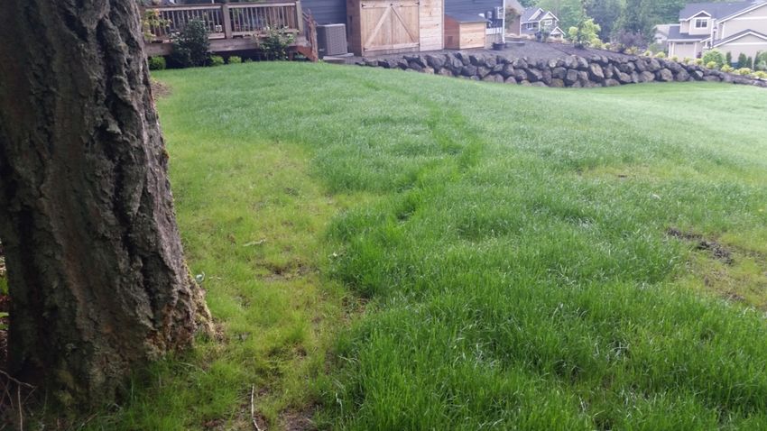
Design:

       Each OSCAR-III coil is designed to treat and dispose of 25 or 50 gpd of
residential strength effluent, depending on soil depth and OSCAR coil model
specified. Minimum vertical separation depth is 12”, except in soil type 1 where a
minimum of 18” of vertical separation is required.

        There are two models of OSCAR-III coils: OS-50 and OS-100. The OS-50 coils
form a 5’ wide single row and the OS-100 coils form a 7.1’ wide single row. Tables
III and IV dictate the overall minimum “shoulder” length for the corresponding
design flow for each coil model. See appendix for details of OS-50 & OS-100 foot
print and specifications. See appendix “A” for more details.
        An OSCAR-III has four (4) sizing criteria: treatment vessel, pump tank,
hydraulic layout, and basal area. The hydraulic layout criterion includes the
number of coils and how they are to be connected. The basal area refers to the
overall foot print of the OSCAR-III sand/soil interface. See below for treatment
vessel requirements.

Treatment Vessel:

       The treatment vessel for the OSCAR-III shall be posted on the Washington
State Department of Health’s List of Registered Sewage Tanks, minimum volume
1,500 gallons.
       For design flows greater than 500 gpd the treatment vessel must be
proportionately upsized for higher design flows. See Appendix “D”.

Pump Tank:

      Pump tank must be at least 1,000 gallons for design flows of 500 gpd or less.
For design flows greater than 500 gpd, the pump tank must be upsized
proportionally to the increase in design flow above 500 gpd.

Hydraulic Layout:

       Coils are arranged in laterals. Each lateral is a single coil or a group of coils
linked in series between the supply and flush manifolds. The OSCAR-III coils are
timed dosed and flushed automatically.
       The standard single family residence OSCAR-III packages with design flows
between 240 to 480 gpd include a headworks (model HWN-.7-RF) for dosing the
OSCAR-III coils. Table I depicts the number of OS-50 coils and laterals required for
a given design flow using an AY McDonald 30 gpm, 1/2 hp, 110 volt turbine pump,
model 22050E2AJ. Table II depicts the number of OS-100 coils and laterals required
for a given design flow using the same pump. The criteria in these tables must be
followed. If a deviation is required, contact Lowridge for assistance.
       The tables also indicate how much excess head, under the pump curve, is
available for supply line elevation lift and friction loss. All manifolds, supply and

                                                                                       !4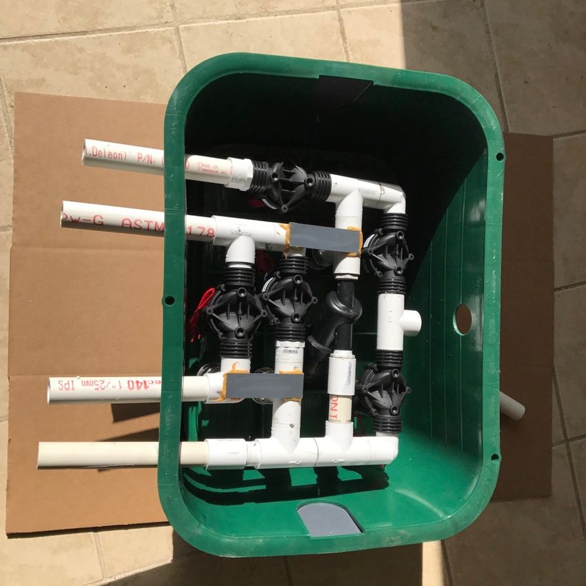
flush lines are assumed to be 1” sch 40 PVC. The designer must calculate the total
dynamic head (TDH) for the OSCAR-III supply line. Use the flow rate indicated
under the heading “Flush GPM” in Table I or II for the corresponding design flow
and coil model to calculate the friction loss of the supply line. If the calculated
TDH is greater than the “Excess TDH” value in Table I or II, call Lowridge for
assistance. TDH is calculated by adding the friction loss of the supply line to the
elevation lift from liquid level in pump tank to the OSCAR-III coils. Use the
following Hazen-Williams formula to calculate friction loss. Always use the Flush
Flow Rate valves when calculating fiction loss.

         1.85

f=L(Q/K)
F= friction loss through pipe in feet of head
L= length of supply line in feet
Q= Flush GPM
K=47.8 (1” sch 40 PVC pipe)

                                      TABLE I
                                  Hydraulic Layout
                                    OS-50 coils
Design          Total    # of      Coils      Dose        Flush      Excess
Flow            Coils    Lats.     per lat. GPM           GPM        TDH
240             10       5         2          3.5         12         50’
300             12       3         4          4.2         12         50'
360             16       4         4          5.6         12         50’
450             18       6         3          6.3         12         50’
480             20       5         4          7           12         50’

                                    TABLE II
                                Hydraulic Layout
                                  OS-100 coils
  Design         Total    # of     Coils      Dose         Flush       Excess
  Flow           Coils    Lats.    per lat. GPM            GPM         TDH
  240            5        5        1          3.5          12          50’
  300            6        3        2          4.2          12          50'
  360            8        4        2          5.6          12          50’
  450            10       5        2          7            12          50’
  480            10       5        2          7            12          50’

                                                                                  !5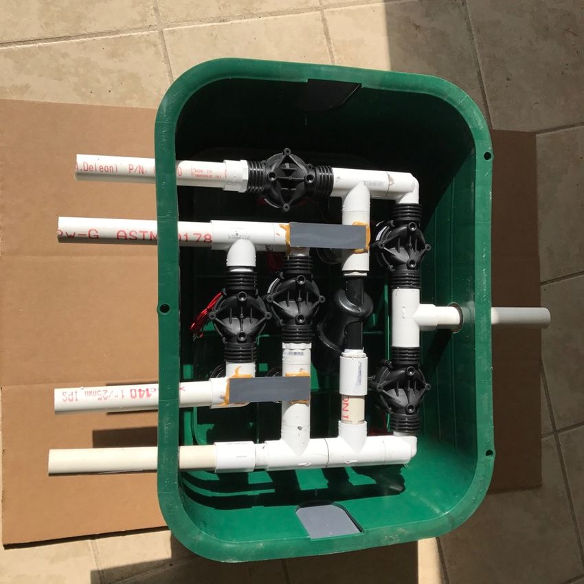
TABLE III
                           Minimum Shoulder Lengths
                                    OS-50
Design Flow                          Minimum Shoulder Length in
                                     Feet
240                                  55.5
300                                     66.5
360                                     88.5
450                                     100
480                                     110.5
The dimensions in Table III represent the minimum required length of the outer
shoulder which include coils, spacing between coils, and shoulders. These lengths
can be extended to match site conditions. Minimum shoulder spacing is 6”. See
illustration below for example of shoulder length.

                                     TABLE IV
                            Minimum Shoulder Lengths
                                      OS-100
 Design Flow                            Minimum Shoulder in Feet
 240                                    35.5
 300                                    42.5
 360                                    57
 450                                    64
 480                                    71
The dimensions in Table IV represent the minimum required length of the shoulder
which include coils, spacing between coils, and shoulder. These lengths can be
extended to match site conditions. Minimum shoulder spacing is 6”. See
illustration below for example of shoulder length.

                                                                                    !6
Basal Area:

       The basal area is comprised of the total area where the sand media is in
contact with the receiving soil. The minimum required basal area is calculated by
dividing the design flow rate by the soil loading rate specified in WAC 246-272A
(local codes may have differing loading rates).

                         Example, Soil type 4 at 240 gpd.

                        240 gpd ÷ 0.6 gpd/ft2 = 400 sq. ft.

Combining Hydraulic Layout and Basal Area Requirements:

        To combine the coil layout and the basal area, start with the coil layout.
Refer to Tables III or IV for minimum shoulder lengths. On flat sites, the coils
should be placed in the center of the basal area. The coils will be arranged in a
single line, although the line can be curved to match site contours. Also, no
emitter shall be placed within 6” of the sand media shoulder. Basal area width
must be a minimum of 7.5’ in all applications
        On sloping sites (up to 20% slope) the coils will be placed parallel to the
contour and one edge of the coils must be placed about 12” from the upslope
basal boundary. There must be at least 6” separation between sand shoulder and
an emitter. With the OS-50 coils there must be at least 6” between the drip tubing
in different coils. With the OS-100 coils there must be 12” spacing between the
drip tubing in different coils. Side slopes of the sand media is at least a 1 to 1
slope. Two inspection ports must be installed: one in the coil area and the other in
the basal area as shown. For inspection port construction, see Appendix.

                                                                                    !7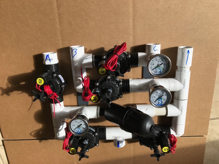
FLAT SITE (12-18” inches soil, OS-50 coil)
                                    OS-480-5

                                            MIN. SHOULDER LENGTH
                                                                                                                                       A

                                                                                                                           1" SUPPLY
 BASAL WIDTH

                                                                                                                             1" RETURN
                                                                             INSPECTION PORT

                                                                             INSPECTION PORT

                                                                                                                                       A

                                                                                                                                 Plan View
                                                                                                                                       NTS

Example: (refer to illustration above and Table III).

240 gpd design flow, soil type 4 (0.6 gpd/ft2), flat site                                      4" SLIP CAP
                                                                                     COIL
                                                 1                                                       1

                  Basal area required = daily design flow ÷ soil loading rate
                                             1
                                                     6"
                                                               6"                              6"
                                                                                                             1

                                                                                                    6"
                                                          6"
                                                                                     60"
                                   400 sq. ft. = 240 gpd ÷ 0.6 gpd/ft2
                                                                    ASTM C-33 SAND                  INSPECTION PORT
                PREPARED SOIL SURFACE

Minimum shoulder length (see Table III) is 55.5 feet.
                                             BASAL WIDTH

Minimum side slopes at 1 : 1 slope @ 12 inches (2 x 12 inches = 2 feet) = 2 feet                                                 Section A
                                                                                                                                           NTS

Minimum basal length= shoulder length + side slopes
                            55.5 feet + 2 feet = 57.5 feet
Basal area width = required basal area ÷ minimum basal length
              = 400 sq. ft. ÷ 57.5 feet = 6.96 or 7.5 feet (minimum basal width)

Basal area dimensions for soil type 4 = 57.5 feet long x 7.5 feet wide.

                                                                                                                      !8
SLOPING SITE (12-18 feet of soil, OS-50 coils)
When calculating the required basal area for a sloping site the same process is
used as a flat site except for one criterion. The side slope value must include the
increased sand depth due to the sloping site. In order to keep the coils level on a
sloping site, additional sand must be placed under the downslope side of the coil.
The greater the sand hight, the greater the side slope. To calculate the additional
sand depth use the following formula:

                        Diameter of coil x % slope of site

      In the illustration below the 20% slope needs an additional 12 inches of sand
to maintain a level coil network.

                    60” (diameter of coil) x 20% = 12 inches

       The additional 12 inches of sand needs to be added to the minimum
required sand of 12 inches to equate to the 24 inches of sand on the downslope
side of the coil.

                                                                                      !9
Example:

240 gpd design flow, soil type 4 (0.6 gpd/ft2), sloping site

            Basal area required = daily design flow ÷ soil loading rate

                        400 sq. ft. = 240 gpd ÷ 0.6 gpd/ft2

Minimum shoulder length (see Table III) is 55.5 feet.

Minimum side slopes at 1 : 1 slope @ 24 inches (24 inches x 2) = 4 feet

Minimum basal area length = shoulder length + side slopes
                           55.5 feet + 4 feet = 59.5 feet
Basal area width = required basal area ÷ minimum basal length
                400 sq. ft. ÷ 59.5 feet = 6.73 feet or 7.5 feet

Minimum basal area dimensions for soil type 4 = 59 feet long x 7.5 feet wide.

    SLOPING SITE (18 inches of soil, OS-100 coils)
When calculating the required basal area for a sloping site the same process is
used as a flat site except for one criterion. The side slope value must include the
increased sand depth due to the sloping site. In order to keep the coils level on a
sloping site, additional sand must be placed under the downslope side of the coil.
The greater the sand hight, the greater the side slope. To calculate the additional
sand depth use the following formula:

                         Diameter of coil x % slope of site

      In the illustration below the 20% slope needs an additional 12 inches of sand
to maintain a level coil network.

                  85 inches (diameter of coil) x 20% = 17 inches

       The additional 17 inches of sand needs to be added to the minimum
required sand of 12 inches to equate to the 29 inches of sand on the downslope
side of the coil.

                                                                                  !10
Example:
240 gpd design flow, soil type 4 (0.6 gpd/ft2), sloping site
Basal area required = daily design flow ÷ soil loading rate
400 sq. ft. = 240 gpd ÷ 0.6 gpd/ft2
Minimum shoulder length (see Table IV) is 35.5 feet.
Minimum side slopes at 1 : 1 slope @ 29 inches (29 inches x 2= 4 feet, 10 inches) =
say 5 feet
Minimum basal area length = shoulder length + side slopes
35.5 feet + 5 feet = 40.5 feet
Basal area width = required basal area ÷ minimum basal length
400 sq. ft. ÷ 40.5 feet = 9.87 feet or 10 feet
!11Minimum basal area dimensions for soil type 4 = 45.5 feet long x 10 feet wide.
Controller:
The LF1P-RF-BLWR control panel shall be used to operate the timed dosing
sequencing of the OSCAR-III. Timer settings for the OSCAR-III are short and very
frequent (7 minutes and 38 seconds off and 22 seconds on).
It is expected that the supply line will stay charged between doses, unless
in eastern Washington where the supply and flush lines drain. It is therefore
strongly recommended to site the OSCAR coils at or above the discharge tank. If
supply and flush lines drain between doses, additional “on” time must be added to
dose cycle.
Set-backs:
When the item to be setback1 from is: Upgradient2 Downgradient3
Setback distance from property lines, 10 feet 30 feet
other soil dispersal components,
driveways, buildings, ditches or
interceptor drains, subsurface storm
water infiltration systems, or any
other development which would either
impede water movement away from the
OSCAR or channel groundwater to the
OSCAR area
Setback distance from well, suction line 100 feet 100 feet
or surface water.
1 The edge of required basal area
2The item is upgradient when liquid will flow away from it upon encountering a water table or restrictive layer.
3The item is downgradient when liquid will flow toward it upon encountering a water table or restrictive layer.
All other set backs are according to local code or WAC 246-272A.
Appendix
Appendix A: Coils
OS-50: The OS-50 OSCAR coil is made with 25’ of custom Netafim Bioline with 0.42
gph emitters @ 6” spacing (50 emitters), an average of 2 emitters per sq. ft. Each
pre-assembled coil has a minimum area of 25 sq. ft. (5’ x 5’). There must be a
minimum of 6” spacing between each coil and a minimum of 6” spacing between
any coil and the should edge. Table III contains the minimum shoulder length for a
given design flow. The “shoulder length” is the total minimum distance from the
outside shoulder edge of the first coil to the opposite end shoulder of the last coil.
!12This dimension includes all the coils, coil spacing, and shoulder spacing on each
end. OS-50 Coils equal 25 gpd with the OS-III system.
OS-100: The OS-100 OSCAR coil is made with 50’ of custom Netafim Bioline
with 0.42 gph emitters @ 6” spacing (100 emitters), an average of 2 emitters per
sq. ft. Each coil has a minimum area of 50 sq. ft. (85”x85”). The actual coil
diameter is 73”. There must be a 12” minimum spacing between the tubing of
differing OS-100 coils and a 6” spacing between any tubing and the shoulder edge.
Table IV contains the minimum shoulder length for a given design flow. The
“shoulder length” is the total minimum distance from the outside shoulder edge of
the first coil to the opposite end shoulder of the last coil. This dimension includes
all the coils, coil spacing, and shoulder spacing on each end. See illustration
below.
OS-100 Coils equal 50 gpd with the OS-III system.
!13Appendix B: Sample Design layouts, flat site (OS-50 coils)
240 gpd 300 gpd OS-600-5
OS-480-5
MIN. SHOULDER LENGTH
A
MIN. SHOULDER LENGTH
A
1" SUPPLY
BASAL WIDTH
1" SUPPLY
BASAL WIDTH
1" RETURN
1" RETURN INSPECTION PORT
INSPECTION PORT
INSPECTION PORT
INSPECTION PORT
A
A
Plan View
Plan View NTS
NTS
240 gpd (Sloping site, OS-100 coils)
4" SLIP CAP 4" SLIP CAP
COIL COIL
1 1 1
1
1 1 1
1 6" 6"
6" 6"
6" 6"
6" 6"
6" 6"
60" FLAT SITE
60" FLAT SITE
ASTM C-33 SAND INSPECTION PORT ASTM C-33 SAND INSPECTION PORT
PREPARED SOIL SURFACE PREPARED SOIL SURFACE
BASAL WIDTH BASAL WIDTH
Section A Section A
NTS
NTS
!14Appendix C: Headworks.
HWN-.7-RF-OS
• 1” Arkal disc filter, mesh, 130 micron
• 1” Arad flow meter
• Three oil filled pressure gauges
• 5 Netafim normally closed solenoid valves
Appendix D: OSCAR-III Parts list.
Each OSCAR-III unit will include (Same as an OSCAR-II Kit):
• LF1P-RF-BLWR control panel
• 1/2 hp, 30 gpm AY Mc Donald pump
• OS-50 or OS-100 Coils
• PVC fittings and drip tubing adapters
• HWN-.7-RF-OS automatic headworks
• Solid ½” poly tubing for connections
• 2 float switches
Appendix E: OSCAR-III coil Connections
!
Manifolds and supply lines are 1” Sch 40 PVC
!15!
Manifold and blank tech line adapter and connection.
!
Blank tech liner and Bioline connection with internal coupling
Appendix F: Inspection ports.
!16OSCAR-II-Tanks
Length
SEE HYDRAULIC LAYOUT ATTACHED
Width
Appendix G: Tanks.
3
S5
S2
S4
1
2
S3
S1
PLAN VIEW
15001000 Gallon
gallon 10001000
Gallongallon
Pre-cast Concrete
Treatment Vessel
Treatment Vessel Single Compartment
Pump Tank Discharge Tank
KS
OR
UNION
W
AD
HE
Appendix H: OSCAR-III Cover Options. HWA
• Minimum volume of 1,000 gallons.
• The vessel must be on Lowridge Onsite Technologies’ list of 4" MIN. FLOATS
There may be a desire to cover the OSCAR with something
approved vessels. PUMP
additional to the
COVERAGE
• The vessel must have testing results from an ANSI certified
specified ASTM C-33 sand. Options include:
wastewater testing facility and can produce effluent quality equal
to or less than 100 mg/l CBOD5 and 75 mg/l TSS.
• landscaping jute mat with grass seed or ground cover plantings CROSS SECTION
• a thin layer of mineral soil low in organic content (On a standard mound system, where soil cover is required, the soil cap can
dry out in the summer months requiring additional irrigation to maintain
vegetative cover.
Appendix I: Cold Weather Options.
In colder climates (eastern Washington) it may be necessary to prevent
freezing in the OSCAR-III headworks. This is especially true with vacation homes
where the houses are vacant in the winter and all power is turned off. In these
situations Lowridge recommends allowing the internal portion of the HWN-.7-RF
headworks to drain between doses. Install the “King Fitting” as shown on the cold
weather tank diagrams.
Reverse Flush Headworks Installation Instructions
The reverse flush headworks can be used in cold weather and non-cold weather
applications. In cold weather applications use the cold weather adapter. In non
cold weather applications use the cap.
!18
Cold weather adapter Non-cold weatherThe standard reverse flush headworks comes assembled to allow for easy
conversion to a cold weather option or non-cold weather option.
Cold Weather
To convert to a cold weather application install the cold weather adapter as shown
below.
Cold weather
!19Glue tail pieces “A, B, C, & B” to their corresponding positions. Do not glue “D”
yet.
Place headworks inside box in pre-drilled holes. Then glue tail piece “D”. Replace
bottom on headworks.
!20Turn headworks right side up on top of tank. Place two 1” spacer pipes under
headworks as shown. Place some soil around spacer pipes to stabilize.
Use the 1” St El 90s and tee to connect both “B” tail pieces together. Connect this
pipe to the 4”x1” tee on the inlet side of the settling tank. Make sure the two “B”
tail pieces drain back to the inlet pipe.
Non-cold weather option
Glue “Cap” on tee and plumb the rest of the headworks as in installation
instructions.
Cap
!21You can also read