MRT 97-M Totalizer Installation and Operating Instructions
←
→
Page content transcription
If your browser does not render page correctly, please read the page content below
Installation and Operating Instructions
                                             3-9000-776 Rev. A
                                               September 2012

MRT 97-M Totalizer
CONTENTS Specifications ................................................................... 1 Battery Installation and Replacement .............................. 2 Dimensions ...................................................................... 2 Theory of Operation ......................................................... 3 Wiring ............................................................................... 3 Typical Applications ......................................................... 3 Definitions ........................................................................ 4 Programming Flowchart ................................................... 8 Operation ......................................................................... 10 Error Messages ................................................................ 11 Analog Output Calibration ................................................ 11 Ordering Information ........................................................ 11
BATTERY INSTALLATION and REPLACEMENT

Battery Installation:
All MRT97M models are shipped without the battery(ies) installed. This preserves battery life when the unit is not
in service.

To install the battery, begin by locating the battery holder. This will require opening the enclosure cover and
removing the MRT97M to expose the battery holder.

The plus terminal of the battery is marked with a (+) symbol stamped into the battery holder. Be sure to install the
battery(ies) correctly.

Install battery(ies) to begin setup procedure. See Programming Flowchart to setup desired operating parameters.

Battery Replacement:

The MRT 97-M has a battery monitor feature which illuminates when the lithium battery voltage approaches its
end of life. A descriptor, “BAT”, illuminates when the battery voltage falls below this predetermined value. The low
battery detector operates correctly with all power options.

The battery, or batteries, should be replaced within several weeks of the first occurrence of low battery warning,
“BAT”. Left unattended, the unit may become inaccurate, cease to operate or malfunction.

Before replacing the battery(ies), Press the ← (left arrow) key to save the totalizer. The display will show "SAVE
TOTAL". This will save the current total value and the total will resume from this value when the new battery(ies)
is(are) installed. NOTE: If the display starts to flash after the "SAvE totAL" message times out, press the "E"
(enter) key. If the message "E FLASH" is displayed, then there was not enough power left to save the setup and
totalizer to flash memory. At this point you must record the totalizer and setup information and re-enter the setup
data after the new battery(ies) is(are) installed.

Install new battery(ies) as described above.

                            WARNING!
         !                  Do not open when an explosive atmosphere is present.

   Standard MRT 97 Enclosure Dimensions                            ATEX Option MRT 97 Enclosure Dimensions
   Part Number: 1-504-05-004-M                                     Part Number: 1-504-05-020-M

                 5.00                                  4.63              5.438                          5.625
                (127)                                  (117)            (138.11)                      (142.88)
                                3/4 NPT                                               3/4 NPT
                                (2) HLS                                               (2) HLS

                                           5.00                                              5.625
                                          (127)                                            (142.88)
            E           M
                                                                        E     M
                                 5/16

                 4.25                                                    4.063
                (108)                                                   (103.2)    5/16
                 5.25
                (133)

                                                  Dimensions are in inches (mm)

                                                               2
THEORY OF OPERATION
Flow rate equation: Flow total equation:
Input Frequency Sum of Input Pulses
Flow Rate Indication = x Time Scaler Flow Total =
FAC FAC
Where Time Scaler is equal to: 60 for rate per minute read out
3600 for rate per hour read out
86400 for rate per day read out
20 Point Linearization Option:
A 20 point linearization table is used to construct a curve describing the relationship of K-Factor and input
frequency. The measured input frequency is used to access the table. A linear interpolation of adjacent point pairs
is used to arrive at the K-Factor at that input frequency. The flow rate and total are then computed based upon the
K-Factor for that measurement sample.
NOTE: For best performance and resolution choose as many decimal places as possible in the K-Factor.
Example: Enter a K-Factor of 1 as 1.000.
WIRING
Several typical applications of the MRT 97-M are shown on the following page. Please observe that the various
pulse inputs and power options may be intermixed in many ways to solve common applications. The isolated pulse
output may be freely used so long as proper polarity is observed.
Caution: When 4-20 mA loop option is provided, the power wiring to the loop power option should always be to
terminals (+) 12 and (-) 11. Accidental wiring to (+) 12 and (-)6 should be avoided since excessive current
flow may result.
Caution: The magnetic pickup input and contact closure input require isolated sensors for proper operation.
Accidental connections to earth may result in erroneous operation of the analog output and/or excessive
current flow.
Caution: Accidental connections from circuit common (3 or 6) to earth or terminal (11) may result in erroneous
operation of the analog output and/or excessive current flow.
3TYPICAL APPLICATIONS
4-20 mA OUTPUT CONFIGURATION PULSE OUTPUT CONFIGURATION
24 VDC
+
Power Shield to be connected to Shield to be connected to
Supply enclosure ground terminal DC Power – Common enclosure ground terminal
- Power
12 1110 9 8 7
12 1110 9 8 7
Supply +
6 5 4 3 2 1
6 5 4 3 2 1
*
Pulse +
Output –
Remote
- + Reset Switch
Strip Chart
Recorder
4-20mA (+)/DC In (+) 12 1 Mag Input 1
4-20mA (+)/DC In (+) 12 1 Mag Input 1 4-20mA (-) 11 2 Mag Input 2
4-20mA (-) 11 2 Mag Input 2 Opto Input (+) 10 3 No Connection
Opto Input (+) 10 3 No Connection Opto Input (-) 9 4 Reset Input Turbine Meter with
Turbine Meter with Opto Out (+) 8 5 Contact Input Mag Pickup
Opto Input (-) 9 4 Reset Input Mag Pickup
Opto Out (+) 8 5 Contact Input Opto Out (-) 7 6 Common
Opto Out (-) 7 6 Common
* Use a 1000Ω resistor for 24 VDC supply
Use a 470Ω resistor for 12 VDC supply
Use a 240Ω resistor for 6 VDC supply
DC POWERED & PREAMP CONFIGURATION PULSE OUTPUT CONFIGURATION - PLC
(–) 24 VDC (+)
Power Shield to be connected to
Supply Common
G enclosure ground terminal
24 VDC
12 1110 9 8 7
B +
6 5 4 3 2 1
12 1110 9 8 7
6 5 4 3 2 1
D P *
C Modicon
E Pulse Output
PLC
A Remote
Reset Switch
Pre-Amp
4-20mA (+)/DC In (+) 12 1 Mag Input 1
4-20mA (+)/DC In (+) 12 1 Mag Input 1 4-20mA (-) 11 2 Mag Input 2
4-20mA (-) 11 2 Mag Input 2 Opto Input (+) 10 3 No Connection
Opto Input (+) 10 3 No Connection Opto Input (-) 9 4 Reset Input Turbine Meter with
Turbine Meter with Opto Input (-) 9 4 Reset Input Opto Out (+) 8 5 Contact Input Mag Pickup
Mag Pickup Opto Out (+) 8 5 Contact Input Opto Out (-) 7 6 Common
Opto Out (-) 7 6 Common
* Use a 1k to 4.7kΩ resistor to trigger counter
MRT-97 requires 20 mA to power unit
Modicon (PLC) requires minimum 15 V input.
PULSE OUTPUT CONFIGURATION - RELAY PULSE OUTPUT CONFIGURATION - TOTALIZER
Common
Sampler Shield to be connected to Shield to be connected to
120 VAC enclosure ground terminal enclosure ground terminal
*
12 1110 9 8 7
12 1110 9 8 7
Totalizer
6 5 4 3 2 1
6 5 4 3 2 1
046378
6-30 VDC (+) + –
Common (–)
4-20mA (+)/DC In (+) 12 1 Mag Input 1 4-20mA (+)/DC In (+) 12 1 Mag Input 1
4-20mA (-) 11 2 Mag Input 2 4-20mA (-) 11 2 Mag Input 2
Opto Input (+) 10 3 No Connection Opto Input (+) 10 3 No Connection
Opto Input (-) 9 4 Reset Input Turbine Meter with Opto Input (-) 9 4 Reset Input Turbine Meter with
Mag Pickup Opto Out (+) 8 5 Contact Input Mag Pickup
Opto Out (+) 8 5 Contact Input
Opto Out (-) 7 6 Common Opto Out (-) 7 6 Common
Relay NOTE: 1) Connect (+) 8 fom MRT-97 to (+) terminal of totalizer and (-)7 from MRT-97 to
* (–) terminal of totalizer
Potter Brumfield model: CNT-35-96 or equal
2) Scaling is done in the MRT-97
1) Current through MRT-97 should be limited to 100mA max. Solid state
relay is suggested.
2) Pulse width may not be adequate to cycle the solenoid valve. A solid
state relay with an adjustable delay release should be considered.
4DEFINITIONS
Save Total: (Save Total) Press the E key while the unit is running to save the total value. The display will show
"save total" for a few seconds. This is a very useful "scratch pad" to save and restore total when replacing the
battery(ies)
ent Code: (enter code) This prompt will only appear if the panel lock is ON. Press the ↑ key to increment each digit.
Press the ← key to step to the next digit to the left. Press the E key to enter the 5 digit code. If the entered
code is correct, the display will advance to the next menu prompt (CLr tot). If incorrect, the display will return to
the run mode.
Clr tot: (clear total) Clears (resets) the totalizer.
Press the E key to clear the total and return to the run mode.
Press the M key to skip and advance to the next menu selection.
fdeC: (factor decimal) Sets the decimal location for the factor. This location is restricted to 3 places (99.999). The
use of this decimal automatically limits the number of decimal locations allowable in the rate and total to
acceptable ranges. Press the ← key to move the decimal. Press the E key to select the displayed decimal
location.
NOTE: For best performance and resolution choose as many decimal places as possible in the K-Factor.
Example: Enter a K-Factor of 1 as 1.000.
faC lInear/20poInt: (factor type) This prompt will only appear if the unit is ordered with the 20 point linearization
option. The 20 poInt linearization selection is recommended for flow meters whose K-factors change with
factors for different flow rates. The lInear setting is used for flow meters whose output is linear over its' entire
different flow rates. This selection allows users to enter up to 20 different frequencies with 20 corresponding K-
operating flow range. Press the ↑ key to step to the desired choice. Press the E key to enter the displayed
factor type.
No / yes set Pnts: (set 20 point?) This prompt allows the user to skip the 20 point setup routine. Select yes for
initial setup or to change the present 20 point values. Select No to skip and keep the existing values.
faC : (factor) This prompt appears on all units with linear inputs. The Factor is the number of pulses per unit volume
for the flow sensor. The pulses/unit volume is implied by the totalizer descriptor when a descriptor is used. The
implied units for the Factor are then as follows:
GAL pulses/gallon
BBL pulses/BBL
MCF pulses/MCF
M3 pulses/M3
Factors from 0.0001 to 99999999 may be used. A "0" value for the factor is not allowed and the unit will default
to "1" in LSD if a "0" entry is attempted . The factor is displayed on the subsidiary (lower) display. Press the ↑
key to increment each digit. Press the ← key to step to the next digit to the left. Press the E key to enter the
displayed factor.
fr# : (frequency for point #) This prompt will only appear when 20 point selected. It sets the frequency for each of
the 20 points (#). Press the ↑ key to increment each digit. Press the ← key to step to the next digit to the left.
Press the E key to enter the desired frequency for point #.
faC# : (factor for point #) This prompt will only appear when 20 point selected. It sets the factor for each of the 20
points (#). Press the ↑ key to increment each digit. Press the ← key to step to the next digit to the left. Press
the E key to enter the desired factor for point #.
NOTE: The display will advance to the next point (Fr#) after each entry of the Fr & Fac until all 20 points are
complete. entering a 0 in the Fr or fac setting will advance the display to the next menu prompt (tdec).
5DEFINITIONS
(continued)
tdeC: (totalizer decimal) Sets the decimal location for the totalizer. The totalizer decimal is not a dummy decimal
and will scale the totalizer display accordingly. (i.e. if the tdec is set in the tenths position (1234567.8), 100 will
be displayed as 100.0). The location of the decimal point allows for greater resolution of both the totalizer
display and the pulse output. The pulse output advances at a rate dependent on the least significant digit of the
totalizer. The totalizer decimal location is restricted to a maximum of 4 places (1234.5678). However, the
number of totalizer decimal locations allowable is reduced with each decimal place added to the factor
decimal. Press the ← key to move the decimal. Press the E key to enter the displayed decimal location.
Note: The selection of the factor decimal point limits the available selections for the number of decimal
points available for the totalizer. This is automatic. Enter your selection of the Factor’s decimal
point before entering the totalizer decimal point to assure the proper selection of the totalizer
decimal point has been made.
tot desC: (totalizer descriptor) This allows you to illuminate one of the available descriptors on the display (GAL,
BBL, MCF, M3, "blank"). Press the ↑ key to select the descriptor. Press the E key to enter the selected
descriptor.
r sCale: (ratemeter scaling) Sets the rate readout. Choose rate per day (day), hour (Hrs) or minutes (nnIn). The
scale setting is shown on the main (upper) display. Press the ↑ key to step to the desired choice. Press the E
key to enter the displayed scale setting.
Note: A rate descriptor corresponding to the above choice will be illuminated on the display.
r deCloC: (ratemeter decimal location) Sets the decimal location for the ratemeter. The ratemeter decimal is not a
dummy decimal and will scale the rate display accordingly. (i.e. if the r decloc is set in the tenths position
(123.4), 100 will be displayed as 100.0). The ratemeter decimal location is restricted to a maximum of 4 places
(.1234). However, the number of ratemeter decimal locations allowable is reduced with each decimal place
added to the factor decimal. Press the ← key to move the decimal. Press the E key to enter the displayed
decimal location.
Note: The flow rate indicator will flash “99999” if the computed flow rate exceeds the 99999
display capability of the indicator. Choose a new decimal point location to avoid this.
NOR# NORMALIZING FACTOR - Normalizes (averages) the data being received. Enter a value from 0 to 9.
Higher settings provide more normalizing (averaging) for a more stable display. Derived from the equation:
(Old Data x "NOR" + New Data)
("NOR" + 1)
delay: (delay) Sets the amount of time (0.1 to 99.9 seconds) that the unit will "look" for valid input data. If pulses
are not detected within this "window", the rate will display 0. The display will update once every second as
long as the unit receives valid data within a second. Some internal mathematics may delay this update.
Press the ↑ key to increment each digit. Press the ← key to step to the next digit to the left. Press the E key
to enter the displayed delay value.
oUt lo: (out low) Sets the low setting for the 4-20 mA analog output. Key in the low rate value at which the unit will
output 4mA. Press the ↑ key to increment each digit. Press the ← key to step to the next digit to the left. Press
the E key to enter the displayed out lo value.
oUt HI: (out high) Sets the high setting for the 4-20 mA analog output. Key in the high rate value at which the unit
will output 20 mA. Press the ↑ key to increment each digit. Press the ← key to step to the next digit to the left.
Press the E key to enter the displayed out hi value.
6DEFINITIONS
(continued)
pUlscale: (pulse out scaling) This allows the unit to output a pulse for each least significant total count divided by
the selected divider. The pulse out can be divided by 1 (d 1), 10 (d 10), 100 (d 100), or turned off (off). With
the divider set at 1, the unit will give a pulse out for every increment of the LSD displayed.
Note: For maximum battery life, turn the pulse output off when pulse output is not used.
Selecting the proper pulse output divider may be needed so that the pulse output
does not exceed the maximum rate of the pulse output. If the pulse output
pulses too quickly a flashing display will result. Pressing the “M” key will result in a display of an error
message “E PULSE”. Press the “E” key to return to the run mode.
P uuidth: (pulse width) Sets the pulse width of the pulse output. Selections are: 0.5 (1Hz), 0.25 (2Hz), 0.125 (4Hz)
or 0.0625 (8Hz). This menu item is skipped if pUlscale is turned off.
loC Code: (lock code) Sets the 5 digit lock code to be entered when the unit prompts ent Code. This allows the user
to gain access to the menu when the unit is locked. Press the ↑ key to increment each digit. Press the ← key
to step to the next digit to the left. Press the E key to enter the displayed code.
Record this number for later use! LOCK CODE: ____________________
loC UnIt: (lock unit) Sets the panel lock ON or OFF. Press the ↑ key to select On or OFF. Press the E key to enter
the displayed selection.
7PROGRAMMING FLOWCHART
RUN MODE RATE Press the M key to enter the programming menu.
TOTAL
If panel M
lock OFF If panel If the panel lock is on, you must enter the 4 digit lock code to gain access
lock ON
to the menu.
ENTER CODE 0000 Press the
Press the
key to increment each individual digit of the code.
key to advance to the next digit.
ent Code
clr tot
Press the E key to enter the displayed code.
E If code
incorrect If the code is correct, display advances to " ", if not, display returns
If code to run mode
correct
Press the E key to clear the totalizer and return to the programming menu.
CLEAR TOTAL E Press the M key to skip and go to next menu item.
CLR ToT
M
Press the key to step the factor decimal to the desired location.
FACTOR FDEC E
Press the E key to enter the displayed decimal location.
Press the M key to skip and keep the existing location
DECIMAL 12345678 NOTE: For best performance and resolution choose as many decimal places as
M possible in the K-Factor. Example: Enter a K-Factor of 1 as 1.000.
FACTOR 20poInt FAC E
Press the key to choose factor type ( 20point linear
or ).
TYPE lInear 20poInt
Press the E key to enter the displayed factor type.
Press the M key to skip and keep the existing factor type.
M
20poInt
selected
lInear
selected
The FAC prompt will only appear if linear is selected or if the unit was
ordered without the 20 point linearization option.
Press the key to increment each individual digit of the factor.
FAC
FACTOR
E Press the key to advance to the next digit.
100 Press the E key to enter the displayed factor.
SET Press the M key to skip and keep the existing factor.
YES
M
SET pnts 20point
20PT YES
No E The prompt will only appear if is selected. This allows
SET pnts
users to bypass the 20 point set up and keep the existing values.
M
Press the key to choose YES or NO.
No YES Press the E key to enter the displayed selection.
selected selected Press the M key to skip (same as selecting NO).
FREQUENCY Fr# E
Press the
point #.
key to increment each individual digit of the frequency for
for POINT # #####
(Fr0-Fr19) Press the key to advance to the next digit.
If Fr1-FR19 = 0 M
Press the E key to enter the displayed frequency.
Press the M key to skip and keep the existing frequency.
If 0 is entered, the display will advance to the next prompt (tdec).
FACTOR for FaC# E
POINT # #####
(FAC0-FAC19)
M Press the key to increment each individual digit of the factor for point #.
Press the key to advance to the next digit.
Press the E key to enter the displayed factor.
# = 19
Press the M key to skip and keep the existing factor.
If 0 is entered, the display will advance to the next prompt (tdec).
Continue On
Next Page
8PROGRAMMING FLOWCHART
(continued)
Continued From Previous Page
TOTAL DECIMAL TDEC E
Press the key to step the totalizer decimal to the desired location.
Press the E key to enter the displayed decimal location.
12345678 Press the M key to skip and keep the existing location
M
GAL Press the key to step to the desired totalizer descriptor.
LIT Press the E key to enter the displayed descriptor.
TOTAL FT3 E
DESCRIPTOR ToT DESC Press the M key to skip and keep the existing descriptor.
M3
"blank" NOTE: When option "D" (rate per day) is ordered; selections are:
(BBL, MCF)
M GAL, BBL, MCF, M3, "blank"
SCALE
SEC
NNIN
SEC E
Press the key to step to the desired scale setting.
Press the E key to enter the displayed scale setting.
(ratemeter) HRS r SCALE Press the M key to skip and keep the existing setting.
(Days) M min, sec, days
NOTE: When option "D" (rate per day) is ordered; selections are:
RATE
DECIMAL
1234 E
Press the key to step the ratemeter decimal to the desired location.
Press the E key to enter the displayed decimal location.
LOCATION R DECLoC Press the M key to skip and keep the existing location
M
NORMALIZATION 1 E
Press the key to increment each individual digit of the "nor" factor.
Press the E key to enter the displayed value.
nor Press the M key to skip and keep the existing value.
M
DELAY
0.1 E
Press the
Press the
key to increment each individual digit of the delay.
key to advance to the next digit.
delay Press the E key to enter the displayed value.
0.1 to 99.9 Press the M key to skip and keep the existing value.
M
Press the key to increment each individual digit of the out low setting
OUT LOW 0000 E
(4mA value). This will only display on units with Analog Output.
Press the key to advance to the next digit.
(4mA) oUT Lo
Press the E key to enter the displayed value.
M Press the M key to skip and keep the existing value.
Press the key to increment each individual digit of the out high setting
OUT HIGH 99999 E
(20mA value). This will only display on units with Analog Output.
Press the key to advance to the next digit.
(20mA) oUT HI
Press the E key to enter the displayed value.
M Press the M key to skip and keep the existing value.
D1
PULSE
SCALER
D 10
D100
D1 E
Press the
output.
key to step to the desired pulse scale divider for the pulse
Pul scale Press the E key to enter the displayed pulse scale divider.
(divider) oFF
Press the M key to skip and keep the existing pulse scale value.
M
.5 Press the key to step to the desired pulse width for the pulse output.
PULSE
WIDTH
.25 .5 E Press the E key to enter the displayed pulse width.
.125 p uuidth Press the M key to skip and keep the existing pulse width.
(seconds) This will not display if Pulse Out is turned OFF.
.0625 M
LOCK 0000 E
Press the
Press the
key to increment each individual digit of the lock code.
key to advance to the next digit.
CODE loc code Press the E key to enter the displayed value.
Press the M key to skip and keep the existing value.
M
TURN LOCK yes yes E
Press the key to step to the desired lock setting.
Press the E key to enter the displayed lock setting.
ON or OFF no loC UnIt Press the M key to skip and keep the existing setting.
M
RUN MODE
9OPERATION
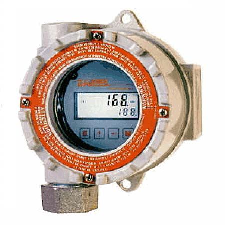
A suitable pulse producing device or flow meter is wired to one of the three pulse inputs provided on the MRT 97-M.
Only one of these inputs is used in a given application. There are no connections to the two unused pulse inputs.
Isolated magnetic pickups may be connected to terminals 1 and 2. Isolated contact closures may be connected to
terminals 5 and 6. Any high level, DC pulse type may be connected to terminals 9(-) and 10(+).
Power to the unit may be provided by internal batteries or the current loop. In all cases, the internal battery will
provide for continued operation in the event primary power is lost.
Once properly wired, the operation of the MRT 97-M is automatic.
The flow totalizer is updated once per second* with battery power, instantaneously with DC or loop power. If no
input counts are received the unit remains in a low power state to conserve power.
The flow total may be cleared by the front panel switch sequence or by a contact closure on the remote reset
terminal to circuit common.
To reset the unit from the front panel, the following key sequence is required:
ent code".
clr tot prompt)
Press M “CLr tot” will be displayed (if the panel lock is on, the display will prompt "
Enter the proper code to advance to the
Press E To clear the total. Unit will return to operation
The flow rate indicator will measure the flow rate once every second* with battery power, 8 times per second with
loop power and display the flow rate.
If the input pulses are not detected within the delay setting (0.1 to 99.9 seconds), a flow rate of 0 will be indicated.
The analog output will be scaled based on the user selected zero and full scale and the measured flow rate. The
analog output is updated at the same time as the rate display.
The pulse output updates at the same rate as the total display in accordance with the instrument setup of pulse
scaling.
* A large delay setting and internal math operations may delay the update rate. A faster update rate occurs when
the unit is loop powered.
10ERROR MESSAGES
The MRT 97-M is provided with extensive self checking which assists the user in the location of setup entry errors
and in reporting malfunctions or unusual operating conditions. When an error occurs, the display will flash. Press
any key to see the error message corresponding to the error that has occurred. Press any key again to acknowl-
edge the error. (If the error can be eliminated by a change of setup values, the unit will automatically advance to
the MENU so that the appropriate setup changes can be made).
Table - 2 illustrates the warning message, problem, and recommended corrective actions.
Diagnostic Error Messages Table-2
WARNING MESSAGE CAUSE CORRECTIVE ACTION
RATE ER Rate Low set Set Rate Hi greater
higher than Rate Hi than Rate Lo
FAC ERR Factor = 0 Set in correct Factor
“BAT” Descriptor Low Battery Replace battery(ies)
E total Total rollover None required
E RATE Rate exceeds 99999 Use lower rate dec point
E pulse Pulse out Overflow Use different pulse scaler or
totalizer decimal point
E FLASH Save to flash Write down displayed total and
memory failed setup values if you are changing
the battery. If total wasn't saved,
it will display an arbitrary total
when new battery is installed. In
this case, reset the total to 0 and
check the setup information.
ANALOG OUTPUT CALIBRATION
CAUTION: Performing the analog output calibration will erase all programming values. Please record all
programmed values before beginning the analog output calibration
If the unit is equipped with the analog output option, the 4-20 mA has been accurately set to 4.000 and 20.000 mA
by the factory. No calibration should be required.
The 4-20 mA output may be verified periodically by installing a digital milliampere meter(DMM) in series with the
analog output and simulating a full scale or over range flow rate.
If the output is out of calibration, perform the following:
Remove power and/or disconnect battery(ies). Hold down the scroll (↑) key and replace the battery. This will
initialize the unit and advance to the analog output calibration mode. Connect a DMM set to read current in series
with a power supply (8.5 to 30 volts DC) to TB12 (+) and TB11 (–). The output should read 4.000 ma (± 0.005). If
it does not, Adjust the numbers on the display up or down until the output reads 4.000 ma (± 0.005). Press the
"E" key. The DMM should now read 20.000 ma (± 0.005). If it does not, Adjust the numbers on the display up or
down until the output reads 20.000 ma (± 0.005). Press "E" and the unit will return to the "RUN" mode.
Ordering Information
Part Number Description
1-504-05-004-M Standard MRT 97-M Rate/Totalizer
1-504-05-020-M ATEX MRT 97-M Rate/Totalizer
11You can also read