MCR-PSP MCR Threshold Value Switch, Programmable
←
→
Page content transcription
If your browser does not render page correctly, please read the page content below
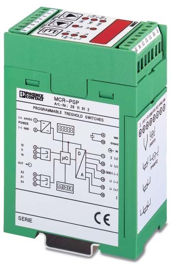
MCR-PSP
MCR Threshold Value Switch, Programmable

1. Short description
• continuous measured value display
• four independently adjustable switching
  thresholds
• with or without galvanic isolation of input signals
• can be programmed using MCR-PI-CONF-WIN
  software
The MCR-PSP modules are used for the monitoring
and regulation of processes. Four switching thresholds
that can be adjusted independently of one another re-
act to the signals of various thermocouple sensors, re-
sistance thermometers and linear resistors that can be
connected directly. An input for analog standard sig-
nals is provided to monitor process signals that have al-
ready been converted.

                   U, I, ϑ, R
                             K1

                             K2
                                            Fig. 1

The module can either be programmed using the
MCR-PI-CONF-WIN software (see page 15) or the
membrane keypad. The device can be adapted to a va-                                           Fig. 2
riety of applications using the keypad at the front and
the display. The LED display constantly displays the
current measured value so that the process value can
also be monitored visually.
The two relays are designed as PDT contacts with ad-
justable time delay, and the limit values of each contact
have a modifiable hysteresis. This option gives you the
advantage of being able to set four switching thresh-
olds independently of one another. In order to provide
additional diagnostics the relays can be connected to
pick up or drop out during a failure mode in auxiliary
voltage to the module. In case of linebreak or short cir-
cuit each of the relais can be set to pick up or drop out
by software or membrane keypad. In the default setting
both relays are set to pick up.
The devices with isolated inputs decouple the field level
and auxiliary power, thus avoiding the creation of
distributed measurement circuits.
The housings are 45 mm wide and connected with
pluggable screw connections (COMBICON) and can
be mounted on commercially available EN mounting                                              Fig. 3
rails.

Headquarters: © Phoenix Contact GmbH & Co. KG • Flachsmarktstraße 8-28 • 32825 Blomberg • Germany
              Phone +49-(0) 52 35-3-00 • Fax +49-(0) 52 35-3-4 1200 • www.phoenixcontact.com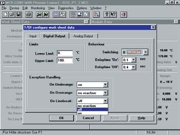
MCR Threshold Value Switch, Programmable - MCR-PSP

                      75                             45
110

                                                                                                                                  8
                                                                                     M3

                                                          Fig. 4                                                                       Fig. 5

                                                                                                      MCR-PSP
                                                                                   with signal input:     Standard signals
       ( ) 24 VDC 1                              9        MM
                                                                                                          Temperature sensors
       POW ER                  00 0 0
                                                                        (A     a
       ( ) GND    2                              10   shield
                                                                                   planned)
                                                              IN
          12      3                      D       11       I( )           (IEC)                rigid    flexible
                                                 12       U( )            [mm2]               solid   stranded    AWG
          11      4             µC
          14      5                          A
                                                 13 GND ( )             Connection data 0.2-2.5         0.2-2.5   24-14
       OUT                                       14       U( )
          22      6                              15       U( )
          21      7                  E           16       I
          24      8
                                                 Fig. 6

                                                                                                                                           Pcs.
2. Description                                                          Type                                              Order No.        Pkt.
MCR threshold value switch,
with dual setpoint relay contacts                                       MCR-PSP                                           28 11 91 2        1
also with galvanically isolated input                                   MCR-PSP-DC                                        28 11 92 5        1

2.1. Technical Data
Input
Input signal:                                                           (see also 2.4. Additional information input, page 4)
• resistance thermometer 2, 3 or 4-wire configuration                   e.g. PT100, Ni etc.
  (acc. to DIN 43 760/DIN IEC 751 or SAMA RC 21-4-1966)
• resistance                                                            0…8 kΩ (only 2-wire connection)
• thermocouple sensors (acc. to DIN IEC 584-1/DIN 43 710)               B, E, J, K, L, N, R, S, T, U
• current                                                               - 30 mA … + 30 mA
• voltage                                                               - 30 V…+ 30 V
Input resistance:
• current                                                               50 Ω
• voltage                                                               200 kΩ
Setting accuracy                                                        0.1 °C / 0.01 V / 0.01 mA / 0.1 Ω
Input protection                                                        transient protection, resistant to overload up to 30 V DC

Display                                                                 Red 7-segment LED indicator, 5-digit, for displaying measured values
                                                                        and setting inputs, switching points etc. Eight red LEDs for displaying
                                                                        the unit of measured value and in edit mode, for displaying the value
                                                                        set.
                                                                        Display frequency: 2 Hz
                                                                        for RTD 3 and RTD 4 1.5 Hz

Keys                                                                    3 membrane buttons for setting the various parameters

                                                          PHOENIX CONTACT page 2 of 15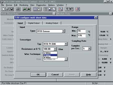
MCR Threshold Value Switch, Programmable - MCR-PSP

Output
Relay level                                                                  2 x PDT contacts / 2 switching points each
                                                                             low/high (settable)
Switching output 1 (K 1)                                                     1 x Um (AgNiO 0.15 + HTV hard gold-plated) 250 V AC, 2 A
Switching point 1, lower limit (SPL)                                         min. input value ... max. input value – double switching tolerance
Switching point 1, upper limit (SPH)                                         min. input value + double switching tolerance ... max. input value

Switching output 2 (K 2 )                                                    1 x Um (AgNiO 0.15 + HTV hard gold-plated) 250 V AC, 2 A
Switching point 2, lower limit (SPL)                                         min. input value ... max. input value- double switching tolerance
Switching point 2, upper limit (SPH)                                         min. input value + double switching tolerance ... max. input value

Cycles                                                                       30 x 106
Setting accuracy                                                             0.1 °C/0.1 °F/0.1 Ω/0.01 V/0.01 mA
Tolerance/Hysteresis around the switching point                              Depending on the type of sensor set
                                                                             (see 2.5. switching tolerance of different inputs, page 11)
Delay time high/low of the relay                                             0.0 ... 1.0 secs, can be set in 0.1 sec. steps
                                                                             1.0 ... 2.0 secs, can be set in 0.2 sec. steps

2.2. General Data
Supply voltage                                                               20 ... 30 V DC
Current consumption                                                          < 60 mA
Temperature coefficient                                                      ≤ 0.01 %/K
Test voltage: auxiliary power supply/input                                   1 kV, 50 Hz, 1 min.
Protection circuit                                                           transient protection, polarity protection
Ambient temperature range                                                    -20 °C to + 65 °C
Display resolution                                                           0.1 °C/ 0.01 V/0.01 mA/0.1 Ω
Offset error (Zero)                                                          typ. < 0.05% F.S.
Gain error (Span)                                                            typ. < 0.05% F.S.
Linearity error                                                              typ. < 0.05K (only for RTD and THC)
Total error                                                                  typ. < 0.1% F.S.
Type of connection:
• Input                                                                      screw terminal block
• Output and supply                                                          pluggable screw terminal block
Installed position / mounting                                                any
Standards and regulations                                                    IEC 664/IEC 664 A/DIN VDE 0110-1:1989-01l

                                                                             Type of housing
                                                                             ABS,                                  see Online catalog
                                                                                                                   color: green
                                                                             Torque value of terminal screws, see Online catalog.
                                                                             Marking systems and mounting material, see Online catalog.
                                                                             The rated cross section (see Online catalog) refers to untreated
                                                                             conductors without ferrules.

2.3. (EMC) electromagnetic compatibility

  c            Complies with EMC guideline 89/336/EEC and low voltage directive 73/23/EEC
  Immunity to interference in acc. with EN 50082-2

  • Electrostatic discharge                                        EN 61000-4-2                               Criterion B
    (ESD)                                                                                                     8 kV discharge in air

  • Electromagnetic HF field:                                      EN 61000-4-3                               Criterion A
    Amplitude modulation                                                                                      10 V/m
    Pulse modulation                                                                                          10 V/m

  • Fast transients                                                EN 61000-4-4                               Criterion B
    (Burst)                                                                                                   I/O/S: 2 kV/5 kHz 1)

  • Surge voltage capacities                                       EN 61000-4-5                               Criterion B
    (Surge)                                                                                                   I/O: 2 kV/42 Ω 1)

  • Conducted disturbance                                          EN 61000-4-6                               Criterion A
                                                                                                              I/O/S: 10 V 1)

  • Noise emission in acc. with EN50081-2                          EN 55011                                   Class A

EN 61000 corresponds to IEC 1000
EN 55011 corresponds to CISPR11

1) I = Input / O = Output / S = Supply

Criterion A: Normal operating behavior within the defined limits.
Criterion B: Temporary impairment of operational behavior that the device corrects itself.

Class A: Area of application: industry, without special installation measures.

                                                           PHOENIX CONTACT page 3 of 15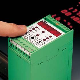
MCR Threshold Value Switch, Programmable - MCR-PSP

2.4. Additional information, input
Resistance    acc. to IEC 751/EN 60751 or DIN 43760
thermometer   SAMA RC 21-4-1966
(RTD sensors) in 2, 3 or 4-conductor circuit

               Type               Standard       Measuring range
               Pt sensors         ( DIN/SAMA )   -200...+850 ˚C
                                                 -328...+1562 ˚F
               Ni sensors         ( DIN/SAMA )   -60...+180 ˚C
                                                 -76...+356 ˚F
               Ni 1000            (Landis&Gyr)   -50...+160 ˚C
                                                 -58...+320 ˚F
               Cu 10              ( SAMA )       -70...+500 ˚C
                                                 -94...+932 ˚F
               KTY 81-110         ( Philips )    -55...+150 ˚C
                                                 -67...+302 ˚F
Thermo-        Type               Standard       Measuring range
couples (TC)
               B                                 +500...+1820 ˚C
                                                 +932...+3308 ˚F
               E                                 -226...+1000 ˚C
                                                 -374...+1832 ˚F
               J                                 -210...+1200 ˚C
                                                 -346...+2192 ˚F
               K                                 -200...+1372 ˚C
                                      IEC584     -328...+2501.6 ˚F
               N                                 -200...+1300 ˚C
                                                 -328...+2372 ˚F
               R                                 -50...+1768 ˚C
               S                                 -58...+3214.4 ˚F

               T                                 -200...+400 ˚C
                                                 -328...+752 ˚F
               L                                 -200...+900 ˚C
                                                 -328...+1652 ˚F
                                    DIN 43710
               U                                 -200...+600 ˚C
                                                 -328...+1112 ˚F
Other          Type                              Measuring range
inputs
               resistance                        0...8 kΩ (in
               (R8000)                           2-conductor circuit)
               voltage                           -30...+30 V
               (U 30)

               current                           -30...+30 mA
               (I 30)
               internal                          -20...+70 ˚C
               cold junction

               User                              0...8 kΩ (in
               (default setting                  4-conductor circuit)
               R8000)

                                                       PHOENIX CONTACT page 4 of 15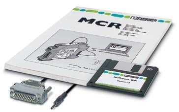
MCR Threshold Value Switch, Programmable - MCR-PSP

3. Overview of inputs that can be
   connected
                                        Nominal range                                               Analog Inputs
 Sensor type     Display
                                lower limit        upper limit                 MG Shield         AGnd U (–)
                                                                                       l (±) U (±)       U (+) l1
   Pt DIN

                              -200 ˚C/-328 ˚F    850 ˚C/1562 ˚F

  Pt SAMA

   Ni DIN

                               -60 ˚C/-76 ˚F      180 ˚C/356 ˚F                            SPH                °C
                                                                                     DTH             K1               V
  Ni SAMA                                                                                  SPL                °F
                                                                                     DTL             K2             mA
                                                                                           H/S

 Ni 1000 L&G                   -50 ˚C/-58 ˚F      160 ˚C/320 ˚F
                                                                                                                  E
                                                                                            Reset         Store

 Cu 10 SAMA                    -70 ˚C/-94 ˚F      500 ˚C/932 ˚F

  TC Type J                   -210 ˚C/-346 ˚F   1200 ˚C/2192 ˚F                    +24V Gnd 12 11 14 22 21 24
                                                                                                    Relay Outputs
                                                                                                                          5126A001

  TC Type K                   -200 ˚C/-328 ˚F   1372 ˚C/2501.6 ˚F
                                                                                                                          Fig. 7

  TC Type E                   -226 ˚C/-374 ˚F   1000 ˚C/1832 ˚F

  TC Type R

                               -50 ˚C/-58 ˚F    1768 ˚C/3214.4 ˚F

  TC Type S

  TC Type T                   -200 ˚C/-328 ˚F     400 ˚C/752 ˚F

  TC Type B                   500 ˚C/932 ˚F     1820 ˚C/3308 ˚F

  TC Type N                                     1300 ˚C/2372 ˚F

  TC Type U                   -200 ˚C/-328 ˚F    600 ˚C/1112 ˚F

  TC Type L                                      900 ˚C/1652 ˚F

   R 8000                          0Ω                8000 Ω

     I 30                        -30 mA              30 mA

    U 30                          -30 V               30 V

     Cold
                               -20 ˚C/-4 ˚F        70 ˚C/158 ˚F
   Junction

    User *                         0Ω                8000 Ω

* Default setting R 8000 (4-conductor system)

                                                    PHOENIX CONTACT page 5 of 15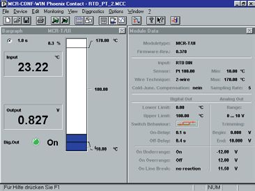
MCR Threshold Value Switch, Programmable - MCR-PSP
4. Connection Technology
The following is true: The shield of the sensor wire must
contact the terminal block shield on the module. It is only
connected to the module on one side. The terminal block
signal ground must be connected to PE.
4.1. Connecting an RTD sensor in 2-conductor 4.2. Connecting an RTD sensor in 3-conductor
technology or a resistor technology
RTD R RTD
PE
2 wire 0...8k PE 3 wire
MG U (–) U (+) MG AGnd U (+)
Shield 5126A005 Shield U () 5126A006
Fig. 8 Fig. 9
4.3. Connecting an RTD sensor in 4-conductor 4.4. Connecting a TC sensor (thermocouple)
technology
RTD TC
PE 4 wire PE
MG AGnd U (+) MG U () U (+)
Shield U () l1 5126A007 Shield 5126A003
Fig. 10 Fig. 11
4.5. Connecting a current signal 4.6. Connecting a voltage signal
l (±30mA) U (±30V)
PE + PE +
MG l (±) AGnd MG U (±) AGnd
Shield 5126A002 Shield 5126A004
Fig. 12 Fig. 13
PHOENIX CONTACT page 6 of 15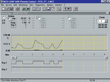
MCR Threshold Value Switch, Programmable - MCR-PSP

5. Operating elements

5.1. Display                                                 5.3. Keys

                                                                                                   E
                                                5126A010
                                                                               Reset       Store                 5126A012
                                              Fig. 14
                                                                                                                 Fig. 15
In operating mode, the 5-digit display shows the input
value measured and in edit mode, the individual setting                      Switching to edit mode. The three keys
options are shown as you “browse” through.                                   must be pressed directly one after
                                                                             another as the module returns to
5.2. LEDs                                                                    operating mode with measured value
                                                                             display after a pause of over 2 seconds.
                SPH             °C
         DTH            K1             V
                SPL             °F                                           Selecting the different settings.
         DTL            K2            mA                          or
                H/S              Ω
                                                5126A011
                                                             E:              Acknowledge setting and continue to
                                             Fig. 16
                                                                             next value.
 In operating mode, the three right-hand LEDs display
 the unit of the input value:                                     and        Reset; cancels edit mode and returns to
– ˚C: degrees Celsius                                        simultaneously: operating mode.
– ˚F: degrees Fahrenheit                                        and E        Store; saves the values set and returns
– Ω: Ohm                                                     simultaneously: to operating mode.
– ˚C and ˚F at the same time (V): Volt
– ˚F and Ω at the same time (mA): milliamperes

The two LEDs in the center and the three to the left light
up in edit mode and show which value is currently being
set:
– K1: The setting refers to relay 1
– K2: The setting refers to relay 2
– SPH: Set Point High; setting of upper switching point
  of K1/K2
– SPL: Set Point Low; setting of lower switching point of
  K1/K2
– H/S: Hysteresis/Switching points; setting of switching
  behavior of K1/K2
– SPH and SPL at the same time (DTH): Delay Time
  High; setting of delay time high of K1/K2
– SPL and H/S at the same time (DTL): Delay Time Low;
  setting of delay time low of K1/K2

                                              PHOENIX CONTACT page 7 of 15
MCR Threshold Value Switch, Programmable - MCR-PSP
6. Setting parameters
6.1. Overview of the menu
Level I Level II
Measured value
display
Selecting type of
Display Selecting unit of
Setting input sensor and resistor
input temperature
(only for RTD)
G 6.2. Systematics of operation
Display wire break
behavior Setting wire break The key combination switches from measured
K1 behavior of value display to edit mode, where the input set is then
K1 and K2 displayed.
K2 Note: The three keys must be pressed directly one after
another. If there is a break of longer than 2 seconds
G between pressing two keys, the module returns to
Display measured value display. The time limit is displayed
Switching points visually by a light running from left to right: if it
SPL K1 extinguishes at the fifth digit, the module returns to
Setting switching measured value display.
points, low (SPL) and When you have switched to edit mode, access the
SPH K1
high (SPH) for K1 desired setting values such as input, wire break
and K2 behavior, switching points etc. using the G key. On the
SPL K2
first vertical level I (see overview), the (pre)set value is
SPH K2 displayed. To alter a value, switch to the second vertical
level II with the key. This is signalled on the display by
G a short illumination of a point in the bottom right-hand
corner. When setting the switching points, the decimal
Display, switching point of the point to be altered lights up briefly.
behavior Setting switching
On the second level II, you can browse through the
K1 behavior for
possible settings with the G key. After the final setting,
K1 and K2
the first setting reappears; it is not possible to browse in
K2
reverse order.
G If an RTD or TC sensor is set as input, select the desired
temperature unit before acknowledging with the E key,
Display, and in the case of RTD sensors, also select the type of
delay time sensor and the size of the resistor.
low/high Only when all the settings have been made on a
DTL K1 horizontal level you may press the E key. This ends all
Setting delay times
low/high for K1 the settings on this level and you move to the next
DTH K1 position on the vertical level I.
and K2
Attention: When you have made all the settings, you
DTL K2 must exit the edit mode by pressing the and E keys at
the same time. Only then are the values permanently
DTH K2 saved.
By pressing the G and keys at the same time, you
G
can exit the edit mode at any time. The old values are
Display test Test options kept and the module returns to operating mode with
measured value display.
In the dark hatched bars of the overviews in the following
chapters for individual settings, you can see how to
return to the particular starting point in each menu.
Below this, you are shown how to select the desired
settings.
PHOENIX CONTACT page 8 of 15MCR Threshold Value Switch, Programmable - MCR-PSP
6.3. Setting the input
First determine the input signal. If it is an RTD or TC sensor, also select the temperature display unit - ˚Celsius or
˚Fahrenheit - , and in the case of RTD sensors, you must also select the type of sensor and the sensor resistance
(at 0 ˚C).
RTD sensors can be wired in 2, 3 or 4-wire circuits (RTD 2, RTD 3 or RTD 4).
Overview: Setting input
Displaying
Measured value
input
display
set
Selecting unit of
Selecting input E E Selecting sensor type E Selecting sensor
temperature
resistance at 0 ˚C
E
E
xxxx.x
Selecting the point
with
, setting a value
between 0 and 9
with G
(0.1...2000 Ω)
E
Cold Junction (inter-
nal cold point) active
Cold Junction (inter-
nal cold point) not
active
for continuation, see following page (page 10)
PHOENIX CONTACT page 9 of 15MCR Threshold Value Switch, Programmable - MCR-PSP
Displaying the
E identification
Example: You wish to connect a Pt100 sensor in acc. with DIN/IEC in 2-conductor technology with ˚C as the unit.
In this case, set: RTD 2 / ˚C / Pt d / 0100.0.
6.4. Setting wire break behavior
You can set the wire break behavior – pick up or drop out – for each of the two relays. The wire break behavior is
independent of the switching behavior set or the set delay times high/low .
Overview: Setting wire break behavior (Linebreak)
Measured Displaying
value input
display set
Display LEDs
Displaying
wire break K1
behavior K1
(relay picks up)
Displaying
wire break
behavior K2 K2
(relay drops out)
PHOENIX CONTACT page 10 of 15MCR Threshold Value Switch, Programmable - MCR-PSP
6.5. Setting switching points
The switching points determine at which value a relay
switches. They may only be set within the measuring
range of the input selected. The high switching point,
SPH, may not be higher than the maximum permissible
value, the low switching point, SPL, must be at least the
lowest permissible value. The distance between SPL
and SPH must be at least twice the value of the swit-
ching tolerance of the input set. The table shows the
measuring range and the switching tolerance of the in-
dividual inputs.
Measuring range and switching tolerance of the in-
dividual inputs Overview: Setting switching points
Input Measuring range Switching tolerance Measured Displaying
3x
value display input set
Resistance thermometer (RTD sensors) Display LEDs
Pt sensors (DIN/SAMA) -200 to 850 ˚C 0.2 K/0.4 ˚F
-328 to 1562˚F
Displaying low
Ni sensors (DIN/SAMA) -60 to 180 ˚C switching point K1
-76 to 356 ˚F SPL K1 SPL
Ni 1000 (Landis & Gyr) -50 to 160 ˚C
-58 to 320 ˚F
Cu 10 (SAMA) -70 to +500 ˚C
-94 to 932 ˚F
Displaying high SPH
Thermocouples (TC sensors) switching point K1
TC J -210 to 1200 ˚C 0.5 K/0.9 ˚F SPH K1 xxxxx
-346 to 2192 ˚F Selecting the
point with E ,
TC K -200 to 1372 ˚C setting the
-328 to 2501.6 ˚F value between 0
and 9 with
TC E -226 to 1000 ˚C Displaying low
-374 to 1832 ˚F switching point
SPL K2 SPL
TC R -50 to 1768 ˚C 0.2 K/0.36 ˚F K2
-58 to 3214.4 ˚F
TC S
TC T -200 to 400 ˚C 0.5 K/0.9 ˚F
-328 to 752 ˚F
TC B 500 to 1820 ˚C 5.0 K/9.0 ˚F Displaying high SPH
932 to 3308 ˚F switching point
SPH K2
TC N -200 to 1300 ˚C 0.5 K/0.9 ˚F K2
-328 to 2372 ˚F
TC U -200 to 600 ˚C
-328 to 1112 ˚F
TC L -200 to 900 ˚C
-328 to 1652 ˚F
Other inputs
Resistor (R 8000) 0 to 8 kΩ 1.0 Ω
Voltage (U) -30 to 30 V 0.01 V
Current (I) -30 to 30 mA 0.0 1 mA
internal cold point -20 to 70 ˚C 0.2 K/0.4 ˚F
(Cold Junction) -4 to 158 ˚F
User* 0 to 8 kΩ 1.0 Ω
* Default setting R 8000 (4-conductor system)
PHOENIX CONTACT page 11 of 15MCR Threshold Value Switch, Programmable - MCR-PSP
6.6. Setting switching behavior Setting options for switching behavior
You can define the switching behavior when a given
Relay picks up when SPH is exceeded,
switching point is reached for each relay. The first two hysteresis is active;
options include a hysteresis, i.e. the behavior of the re- For course of hysteresis, see fig. 17.
lay depends on the direction from which a swtching Relay picks up when value below SPL,
point is reached. hysteresis is active;
For the remaining options, with the exception of the last For course of hysteresis, see fig. 18.
two (“on” and “off”), a switching tolerance is accounted
for to prevent the relay contact from “fluttering”. The re- Relay picks up when value below SPL
lay is not switched until the switching point plus swit-
ching tolerance has been reached.
At “on”, the relay is permanently picked up. It only re- Relay picks up when SPL is exceeded
acts when there is a case of wire break and the setting
for such a case for the relay is dropout; for “off”, the re-
lay only reacts when there is a case of wire break and Relay picks up when value below SPH
the setting for such a case for the relay is picked up.
To the right you will find a list of the setting options for
the switching behavior and their meaning. Relay picks up when SPH is exceeded
Relay picks up between SPL and SPH
Relay picks up outside of SPL and SPH
Relay is permanently dropped out
Relay is permanently picked up
The points below the symbols indicate SPL and SPH.
Overview: Setting switching behavior
Measured value
Displaying input set 7x
Course of hysteresis from
display
Display LEDs Relay state
Displaying K1
switching energized
behavior K1 Selecting one
H/S
of the 10
possibilities
with . not energized
(Overview of
SPL SPH Input signal
the options on
Displaying the next page) 5126A008
switching
behavior K2 K2 Fig. 17
H/S
Course of hysteresis from
Relay state
energized
not energized
SPL SPH Input signal
5126A009
Fig. 18
PHOENIX CONTACT page 12 of 15MCR Threshold Value Switch, Programmable - MCR-PSP
6.7. Setting delay times low/high
You can set a delay time high (DTH) and a delay time low (DTL) for each relay. The dropout or pickup time of the
relay is then delayed by the given time. You can select the period from values between 0.1 and 2.0 seconds, from
0.1 to 1.0 in steps of one tenth, from 1.0 onward in steps of two tenths.
Overview: Setting delay times low/high
Displaying
Measured value
input 9x
display
set
Display LEDs
Displaying
delay time low K1
(DTL) K1 DTL
Displaying
delay time high DTH K1
(DTH) K1
Selecting the period with G ;
Values of between 0.0 and 1.0
can be chosen in steps of one
tenth and values between 1.0
and 2.0 in two tenths
Displaying of a second
delay time low
(DTL) K2 DTL K2
Displaying
delay time high DTH
(DTH) K2
K2
6.8. Activating test mode
In test mode, you can test both the LEDs and the outputs. During the LED test, all the segments of the display and
all the LEDs are activated one after another. During the outputs test, you can switch each relay on and off as re-
quired.
Overview: Activating test mode
Displaying
Measured value
input 13x
display
set
Display LEDs
Display test (runs
E through the individual
segments and LEDs)
E switching over
(end with E!)
E
E switching on
(end with E!)
PHOENIX CONTACT page 13 of 15MCR Threshold Value Switch, Programmable - MCR-PSP
7. Error messages
7.1. Error messages in operating mode
Error display Cause Remedy
E. LB Wire break Check wiring/repair
Input signal too high Check whether the input signal is within the
permissible range (compare table page 5),
and if not, alter to permissible range.
E. CJ Cold junction provides invalid temperature Adjust temperature to valid range.
(only in the case of type TC inputs and Cold
Junction).
Ambient temperature too high or too low
Sensor defect (most improbable) Send device in to be repaired.
7.2. Error messages in edit mode
Error display Cause Remedy
E.type Hardware fault Switch supply on and off. If this is
E.Unit unsuccessful, replace the module.
E.REL
E.SPH1 The upper switching point for K1 is higher The setting is automatically set to the highest
than the highest permissible value. permissible value when the E key is pressed
E.SPH2 The upper switching point for K2 is higher again.
than the highest permissible value.
E.SPL1 The lower switching point for K1 is lower than The setting is automatically set to the lowest
the lowest permissible value. permissible value when the E key is pressed
E.SPL2 The lower switching point for K2 is lower than again.
the lowest permissible value.
E.SP1 The lower switching point for K1 plus Reset the switching points. Twice the value of
switching tolerance is higher than the highest the switching tolerance must lie between SPL
switching point. and SPH.
E.SP2 The lower switching point for K2 plus (compare table page 11/"Setting switching
switching tolerance is higher than the highest points")
switching point.
E.RTD The sensor resistance has not been set for The resistance is set automatically to 2000 Ω
an RTD sensor or does not lie within the after the E key is pressed again.
permissible range up to 2000 Ω.
PHOENIX CONTACT page 14 of 15MCR Threshold Value Switch, Programmable - MCR-PSP
8. Configuration software
MCR-CONF-WIN-…
for
• MCR-T-UI-… temperature transducer
• MCR-PSP-… threshold value switch
Application: Heating controllers with alarm function
°C
100
Alarm
80 Heating OFF
70 Heating ON
OUT MCR-CONF-WIN
configuration software
Pcs.
Description Type Order No. Pkt.
MCR configuration software, for programming the
MCR-T-…- and MCR-PSP-… modules,
with 3 1/2" discs, manual, 4 sheets DIN A4
marking labels (112 pieces) German MCR-CONF-WIN 28 14 13 9 1
English MCR-CONF-WIN-GB 28 14 32 0 1
The MCR configuration software is used to
configure and visualize all parameters for the MCR configuration software, as above,
for NT™ computers German MCR-CONF-WIN-NT 28 14 75 5 1
MCR-PSP-... threshold value switch and the English MCR-CONF-WIN-NT-GB 28 14 76 0 1
MCR-T-UI-... temperature transducer.
The MCR CONF-WIN software runs under DEMO software for programming under English MCR-CONF-WIN-DEMO-GB 28 14 40 1 1
Windows 3.1x, 95, 98 and NT German MCR-CONF-WIN-DEMO 28 14 30 4 1
Windows 3.1x, Windows 95™ and under Software adapter cable
Windows 98™. (Stereo jack plug/SUB-D 25-pos.), 1.2 m MCR-TTL/RS232-E 28 14 38 8 1
The new MCR-CONF-WIN-NTsoftware for programming MCR-T-UI… modules
Software adapter cable
has been specially developed for computers (6-pos./SUB-D 25-pos.), 1.5 m MCR-TTL/RS232 28 14 39 1 1
with Windows NT™. for programming MCR-PSP modules
The modules are configured via a serial Cable adapter, flexible,
for the transition from 9 to 25-pos. D-SUB plug connector PSM-KAD-9SUB25/BS 27 61 29 5 1
interface. A label is automatically produced
by the software, and can be attached to the Labels, for marking
module. MCR-T-UI…modules, MCR-ET 38 X 35 WH 28 14 31 7 1
4 sheets DIN A4 (112 labels)
http://www.phoenixcontact.com
TNR: 5104163-00
Configuration of the input data of the MCR-T-UI-…-modules Configuration of the transistor switching output of the
MCR-T-UI-…modules
15.04.99
PHOENIX CONTACT
Temperature curve represented in a block diagram Temperature curve and switching behavior with monitoring
function
PHOENIX CONTACT page 15 of 15You can also read